Table of Contents
Advertisement
Quick Links
RIPPLE System Integrator
Installation Manual
THIS MANUAL DESCRIBES THE INSTALLATION PROCEDURE FOR THE
POYNTING GROUP (PTY) LTD.
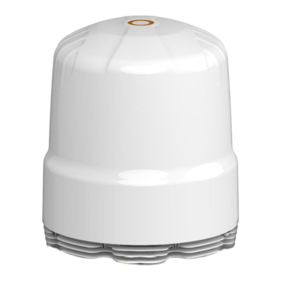
RIPPLE ANTENNA SYSTEM
This system has been purpose designed as a high-performance LTE, 4G, and 5G antenna
system aimed at router manufacturers requiring an antenna system platform; to facilitate
high-speed internet and highly reliable connections in a 'near-shore' telecommunications
tower.
Prepared by: R&D – Technical Support Engineer, Poynting Antenna
Poynting Group (Pty) Ltd
Registration Number: 2014/239013/07
Rev 2.0
www.poynting.tech
Advertisement
Table of Contents

Related Manuals for Poynting RIPPLE


Summary of Contents for Poynting RIPPLE
- Page 1 ‘near-shore’ telecommunications tower. Prepared by: R&D – Technical Support Engineer, Poynting Antenna Poynting Group (Pty) Ltd Registration Number: 2014/239013/07 Rev 2.0...
-
Page 2: Table Of Contents
REQUIRED TOOLS ............................6 ANTENNA INSTALLATION ............................7 3.1. UNPACKING THE BOX STEP-BY-STEP ......................7 OPENING THE ANTENNA AND REMOVING THE RADOME ..................10 FITTING THE ROUTERS INSIDE THE RIPPLE .......................12 RECOMMENDED ROUTER BRACKET MOUNTS FOR RIPPLE ..................14 6.1. A-BRKT-071-V1-01.............................14 6.2. -
Page 3: Ripple System Integration
Therefore, the installation site of the RIPPLE should be chosen accordingly to minimize blockage caused by the structures on the vessel. It is advised that the RIPPLE antenna system be mounted high enough to minimize the effects of surrounding structures. Large, solid, structures will cause significant signal loss while wire rope stays, lifelines, small-diameter handrails, and other accessories may cause little to no noticeable loss. -
Page 4: Safe Access From Radiation Hazard
RADAR Antenna and a minimum of 15 feet (4.6 m) away from the high-power short-wave radars. The S-Band RADAR operates at frequencies between 2.9 to 3.1 GHz. Since the RIPPLE is designed to be an ultrawide bandwidth antenna, it can receive signals in the frequency range from 617 to 6000 MHz. - Page 5 It has been tested to give exceptional performance and outperforms any standard omni- directional antenna that has been tested. The RIPPLE has been tested and evaluated in field trials, off the coast of Cape Town in South Africa, which delivered excellent performance in challenging circumstances and environments.
-
Page 6: Tools Included In Kit
2. TOOLS INCLUDED IN KIT 2.1. REQUIRED TOOLS Poynting Group (Pty) Ltd Registration Number: 2014/239013/07 Rev 2.0 Page 6 of 30 www.poynting.tech... -
Page 7: Antenna Installation
Remove all four cable ties by cutting them off the rods. Step 2. Remove the top rod; then proceed to remove the left and right-side rods as shown below. NOTE: Do not remove the base rod. Poynting Group (Pty) Ltd Registration Number: 2014/239013/07 Rev 2.0 Page 7 of 30... - Page 8 4.2. The Left side support will have a sticker saying, “Open here”. Pull the lid of the side support up to open it; then proceed to take out your hex socket tool gift box; as shown below: Poynting Group (Pty) Ltd Registration Number: 2014/239013/07 Rev 2.0 Page 8 of 30 www.poynting.tech...
- Page 9 Step 5. Slide the RIPL Antenna out of the box as shown below: Poynting Group (Pty) Ltd Registration Number: 2014/239013/07 Rev 2.0 Page 9 of 30 www.poynting.tech...
-
Page 10: Opening The Antenna And Removing The Radome
Using the 5mm Allen/hex key in the provided tool kit and unscrew the M8 cap screws. The Cap screws are captive screws and only need to be unscrewed till it drops loose into the cavity below. Continue to the next step. Poynting Group (Pty) Ltd Registration Number: 2014/239013/07 Rev 2.0 Page 10 of 30 www.poynting.tech... - Page 11 Step 4. While lifting Radome upwards push it backwards until it reaches a 90° angle. Please look at the image below and continue to the next step. Poynting Group (Pty) Ltd Registration Number: 2014/239013/07 Rev 2.0 Page 11 of 30...
-
Page 12: Fitting The Routers Inside The Ripple
5. FITTING THE ROUTERS INSIDE THE RIPPLE Step 1. Use the 4mm Allen key to loosen the M6 countersunk screws in the mounting plate as shown below: Step 2. Remove the loosened M6 countersunk screws; then proceed to remove the mounting plate... - Page 13 Step 4. Remove the main router plate with the pillars from the heatsink as shown below: Note: main router plate is now ready for routers to be mounted onto it. Poynting Group (Pty) Ltd Registration Number: 2014/239013/07 Rev 2.0 Page 13 of 30...
-
Page 14: Recommended Router Bracket Mounts For Ripple
6. RECOMMENDED ROUTER BRACKET MOUNTS FOR RIPPLE Dimensions [ w x h x d] 6.1. A-BRKT-071-V1-01 FITS 4 x ROUTERS WITH DIMENSIONS OF: 95.1mm x 44.2mm x 132mm FITS 2 x ROUTERS WITH DIMENSIONS OF: 190.2mm x 44.2mm x 132mm 6.2. -
Page 15: Connector Layout Inside The Antenna
The verticals (V) are the medium to high gain OMNI antennas. The horizontals (H) are the low-gain OMNI antennas. Step 1. Please study the following pictures to decide how to do cable management for routers installed. RIPPLE-0016 Configuration: This configuration connects 4 x (4x4) Routers (see Page 16) to • 8x Vertical Dipoles •... -
Page 16: A-Ripl-0016-V1-01 Lte/5G Antenna Structure
7.2. A-RIPL-0016-V1-01 LTE/5G ANTENNA STRUCTURE Connecting 4 x (4x4) Routers to RIPPLE-0016 (A-RIPL-0016-V1-01) Please refer to page 20 which details the Router connections to the RIPPLE-0016 base plate. Poynting Group (Pty) Ltd Registration Number: 2014/239013/07 Rev 2.0 Page 16 of 30... -
Page 17: A-Ripl-0008-V1-01 Lte/5G Antenna Structure
7.3. A-RIPL-0008-V1-01 LTE/5G ANTENNA STRUCTURE Connecting 2 x (4x4) Routers to RIPPLE (A-RIPL-0008-V1-01) Please refer to page 21 which details the router connections to the RIPPLE-0008 base plate. Poynting Group (Pty) Ltd Registration Number: 2014/239013/07 Rev 2.0 Page 17 of 30... -
Page 18: A-Ripl-0008/0016-V1-01 Gps/Wifi Antenna Structure
Connecting 4x Wi-Fi Antennas and 2x GPS Antennas RIPPLE (A-RIPL-0008-V1-01) and (A-RIPL-0016-V1-01) Please refer to page 20 or 21 which details the router connections to the RIPPLE-0008 or RIPPLE-0016 base plate, depending on the Model being deployed. Poynting Group (Pty) Ltd Registration Number: 2014/239013/07 Rev 2.0... -
Page 19: Rf Cable Connection
Radio Frequency Bulkhead Connections: Pages 20 and 21 detail the layout of the RF connections to the different Antenna elements. Following the recommendation to mount the RIPPLE as high as possible above the waterline, possibly on one of the Mast telecommunication equipment extensions. -
Page 20: A-Ripl-0016-V1-01
The overlay below details the connector positions and their connected Antenna radiation direction. 8.1. A-RIPL-0016-V1-01 NOTE: TURN THE PAGE HORIZONTALLY TO VIEW Poynting Group (Pty) Ltd Registration Number: 2014/239013/07 Rev 2.0 Page 20 of 30 www.poynting.tech... -
Page 21: A-Ripl-0008-V1-01
The overlay below details the connector positions and their connected Antenna radiation direction. 8.2. A-RIPL-0008-V1-01 NOTE: TURN THE PAGE HORIZONTALLY TO VIEW Poynting Group (Pty) Ltd Registration Number: 2014/239013/07 Rev 2.0 Page 21 of 30 www.poynting.tech... -
Page 22: Ethernet And Power Cables
Carefully route the Ethernet- and Power Cable through the compression glands provided. Route the cables with adequate slack to reach the different points where they should connect. CABLE ENTRY POINT Poynting Group (Pty) Ltd Registration Number: 2014/239013/07 Rev 2.0 Page 22 of 30... -
Page 23: Connect Cables To Router(S)
(the labels are printed on the heat-shrink, at the cable ends). 11. REPLACING THE ASSEMBLED ROUTER ASSEMBLY Replace and fasten the M6 cap screws holding the router assembly in place. Poynting Group (Pty) Ltd Registration Number: 2014/239013/07 Rev 2.0 Page 23 of 30... -
Page 24: Connecting The Rf, Ethernet And Power Cables
Before closing the Radome connect the RF Cables as per the Diagram on Pages 20 and 21. Connect the Ethernet Cable to the appropriate Router Ports. Connect the Power Cable as required. CLOSING THE RIPPLE Assembled router(s) in RIPPLE. Step 1. Pull the Radome forward as shown below: Poynting Group (Pty) Ltd Registration Number: 2014/239013/07 Rev 2.0... - Page 25 Step 3. Push the M8 captive screws upwards and fasten them using the 5mm Allen key as shown below: Step 4. The closing process is now complete. Poynting Group (Pty) Ltd Registration Number: 2014/239013/07 Rev 2.0 Page 25 of 30 www.poynting.tech...
-
Page 26: Antenna Mounting Templates
14. ANTENNA MOUNTING TEMPLATES OVERVIEW MOUNTING HOLES 9” (228.6mm) apart Poynting Group (Pty) Ltd Registration Number: 2014/239013/07 Rev 2.0 Page 26 of 30 www.poynting.tech... -
Page 27: Mounting The Antenna
17. GROUNDING AND RF PROTECTION All metal parts of the RIPPLE should be grounded to bare metal that is common to the hull of the vessel. This is commonly accomplished by attaching a ground wire/cable from the upper base plate ground point to a ground stud on the mounting mast near the base of the radome. -
Page 28: Installation Check
18. INSTALLATION CHECK The RIPPLE antenna system provides excellent radio frequency reception capabilities to enhance the near-shore communication capabilities of marine routers. Installing the router/s in the cavity provided therefore is left to the Integrator to decide how to best integrate the routers and ancillary network communication equipment. - Page 29 Lightning discharge, or o Operation of the product in the wrong environment, or o Modification or alteration of the product, or o Normal expect wear and tear. Poynting Group (Pty) Ltd Registration Number: 2014/239013/07 Rev 2.0 Page 29 of 30...
- Page 30 A: Unit 4, N1 Industrial Park, Landmarks Ave, Samrand, 0157, South Africa P: PO Box 76579, Wendywood, 2144, South Africa T: +27 12 657 0050 | E: info@poynting.tech Europe A: Regus Business Center Neue Messe Riem, Kronstadter Straße 4, 81677 München, Germany T: +49 89 7453 9002 | E: sales-europe@poynting.tech...
Need help?
Do you have a question about the RIPPLE and is the answer not in the manual?
Questions and answers