Table of Contents
Advertisement
Quick Links
Using the LMG3410-HB-EVM Half-Bridge and LMG34XX-
General TI High Voltage Evaluation User Safety Guidelines
Always follow TI's set-up and application instructions, including use of all interface components within their
recommended electrical rated voltage and power limits. Always use electrical safety precautions to help
ensure your personal safety and the safety of those working around you. Contact TI's Product Information
Center
http://support/ti./com
Save all warnings and instructions for future reference.
Failure to follow warnings and instructions may result in personal injury, property damage, or
death due to electrical shock and/or burn hazards.
The term TI HV EVM refers to an electronic device typically provided as an open framed, unenclosed
printed circuit board assembly. It is intended strictly for use in development laboratory environments,
solely for qualified professional users having training, expertise, and knowledge of electrical safety risks in
development and application of high-voltage electrical circuits. Any other use and/or application are strictly
prohibited by Texas Instruments. If you are not suitably qualified, you should immediately stop from further
use of the HV EVM.
•
Work Area Safety:
– Maintain a clean and orderly work area .
– Qualified observer(s) must be present anytime circuits are energized.
– Effective barriers and signage must be present in the area where the TI HV EVM and its interface
electronics are energized, indicating operation of accessible high voltages may be present, for the
purpose of protecting inadvertent access.
– All interface circuits, power supplies, evaluation modules, instruments, meters, scopes and other
related apparatus used in a development environment exceeding 50 V
electrically located within a protected Emergency Power Off (EPO) protected power strip.
– Use a stable and non-conductive work surface.
– Use adequately insulated clamps and wires to attach measurement probes and instruments. No
freehand testing whenever possible.
•
Electrical Safety:
As a precautionary measure, it is always a good engineering practice to assume that the entire
EVM may have fully accessible and active high voltages.
– De-energize the TI HV EVM and all its inputs, outputs, and electrical loads before performing any
electrical or other diagnostic measurements. Confirm that TI HV EVM power has been safely de-
energized.
– With the EVM confirmed de-energized, proceed with required electrical circuit configurations, wiring,
measurement equipment hook-ups and other application needs, while still assuming the EVM circuit
and measuring instruments are electrically live.
– When EVM readiness is complete, energize the EVM as intended.
SNOU140A – April 2016 – Revised May 2017
Submit Documentation Feedback
BB-EVM Breakout Board EVM
WARNING
for further information.
Using the LMG3410-HB-EVM Half-Bridge and LMG34XX-BB-EVM Breakout
Board EVM General TI High Voltage Evaluation User Safety Guidelines
Copyright © 2016–2017, Texas Instruments Incorporated
SNOU140A – April 2016 – Revised May 2017
/75 VDC must be
RMS
Preface
1
Advertisement
Table of Contents

Subscribe to Our Youtube Channel
Related Manuals for Texas Instruments LMG3410-HB-EVM


Summary of Contents for Texas Instruments LMG3410-HB-EVM
- Page 1 Any other use and/or application are strictly prohibited by Texas Instruments. If you are not suitably qualified, you should immediately stop from further use of the HV EVM.
- Page 2 For safety, use of isolated test equipment with overvoltage and overcurrent protection is highly recommended. Using the LMG3410-HB-EVM Half-Bridge and LMG34XX-BB-EVM Breakout SNOU140A – April 2016 – Revised May 2017 Board EVM General TI High Voltage Evaluation User Safety Guidelines Submit Documentation Feedback Copyright ©...
-
Page 3: Table Of Contents
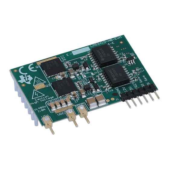
Using the LMG3410-HB-EVM Half-Bridge and LMG34XX- BB-EVM Breakout Board EVM The LMG3410-HB-EVM features two LMG3410 600V/12A GaN power transistors with integrated drivers that are configured in a half bridge with all the required bias circuit and logic/power level shifting. Essential power stage and gate driving high frequency current loops are fully enclosed on the board to minimize parasitic inductances, reducing voltage overshoots and improving performance. -
Page 4: Description
Trademarks All trademarks are the property of their respective owners. Description The LMG3410-HB-EVM operates as a daughter card as part of a larger custom designed system or with the LMG34XX-BB-EVM breakout motherboard. LMG3410-HB-EVM The LMG3410-HB-EVM configures two LMG3410 GaN FETs in a half bridge. All the bias and level shifting components are included, allowing low side referenced signals to control both FETs. -
Page 5: Simplified Lmg3410-Hb-Evm Schematic
1.1.1 FAULT The FAULT pin of LMG3410-HB-EVM is active low when an under voltage lockout on an auxiliary voltage rail, over temperature or overcurrent even occurs on the LMG3410. The FAULT signal for both LMG3410 devices are level shifted to AGND, where they are logic AND connected to the FAULT pin. - Page 6 1.1.3 Bootstrap Mode The LMG3410-HB-EVM card can be modified to operate in bootstrap mode, where the 12V bias voltage is used to power both LMG3410 devices. This can be achieved by removing U3, U4 and R2, and placing a 20 Ω resistor on R1, a 0 Ω resistor on R18 and a 600V SOD-123 diode on D1, such as Micro Commercial Components UFM15PL-TP.
- Page 7 The FAULT LED will still illuminate when either LMG3410 has an active fault, regardless of the position of FAULT Protect jumper. Typical Applications The LMG3410-HB-EVM is designed for use in AC/DC, DC/DC and DC/AC applications • Totem-Pole PFC converters •...
-
Page 8: Schematic
AGND AGND ISO_RET_L_B ISO_RET_H_B Copyright © 2016, Texas Instruments Incorporated Figure 3. LMG3410-HB-EVM Schematic Using the LMG3410-HB-EVM Half-Bridge and LMG34XX-BB-EVM Breakout SNOU140A – April 2016 – Revised May 2017 Board EVM Submit Documentation Feedback Copyright © 2016–2017, Texas Instruments Incorporated... -
Page 9: Recommended Footprint For Lmg3410-Hb-Evm
Schematic www.ti.com Figure 4. Recommended Footprint for LMG3410-HB-EVM SNOU140A – April 2016 – Revised May 2017 Using the LMG3410-HB-EVM Half-Bridge and LMG34XX-BB-EVM Breakout Board EVM Submit Documentation Feedback Copyright © 2016–2017, Texas Instruments Incorporated... -
Page 10: Lmg34Xx-Bb-Evm Schematic
PGND2 AGND ACMGND AGND2 Copyright © 2016, Texas Instruments Incorporated Figure 5. LMG34XX-BB-EVM Schematic Using the LMG3410-HB-EVM Half-Bridge and LMG34XX-BB-EVM Breakout SNOU140A – April 2016 – Revised May 2017 Board EVM Submit Documentation Feedback Copyright © 2016–2017, Texas Instruments Incorporated... -
Page 11: Test Setup
Function Generator: Capable of 0 V to 5 V square wave output with adjustable duty cycle and frequency in desired operating range. It is recommended to operate the LMG3410-HB-EVM and LMG34XX-BB-EVM with a switching frequency between 50 kHz to 200 kHz. -
Page 12: Recommended Connection Points
Figure 7. Recommended Connection Points PCB Notes: • Probe points for gate drive logic • 100 mil header for PWM input, PWM signals to LMG3410-HB-EVM and FAULT output • BNC connector for PWM input • 12V bias supply input •... -
Page 13: Test Point Functional Description
Header to connect PWM, FAULT logic HB Card PIN Connector to interface LMG3410-HB-EVM board SNOU140A – April 2016 – Revised May 2017 Using the LMG3410-HB-EVM Half-Bridge and LMG34XX-BB-EVM Breakout Board EVM Submit Documentation Feedback Copyright © 2016–2017, Texas Instruments Incorporated... -
Page 14: Test Procedure
6 (PWM) and pin 5 (GND) at B. • Enable an external fan to direct airflow across the heatsink attached to the LMG3410-HB-EVM Startup and Operating Procedure The following procedure is recommended to enable the LMG34XX-BB-EVM with the LMG3410-HB-EVM: 1. -
Page 15: Typical Characteristics
Figure 9. Recommended Probe Connection for High Figure 8. Recommended Probe Connection for Logic Voltage Switch Node Signals SNOU140A – April 2016 – Revised May 2017 Using the LMG3410-HB-EVM Half-Bridge and LMG34XX-BB-EVM Breakout Board EVM Submit Documentation Feedback Copyright © 2016–2017, Texas Instruments Incorporated... -
Page 16: Recommended Configuration For Heatsink And Fan
Figure 13. High to Low Transition Waveform with 480V input, 100kHz, 30% duty cycle, 6A output input, 100kHz, 30% duty cycle, 6A output Using the LMG3410-HB-EVM Half-Bridge and LMG34XX-BB-EVM Breakout SNOU140A – April 2016 – Revised May 2017 Board EVM Submit Documentation Feedback Copyright ©... -
Page 17: Evm Assembly Drawing And Pcb Layout
EVM Assembly Drawing and PCB Layout www.ti.com EVM Assembly Drawing and PCB Layout Figure 15. LMG3410-HB-EVM Inner Copper Layer 1 Figure 14. LMG3410-HB-EVM Top Layer and Components Figure 17. LMG3410-HB-EVM Bottom Layer and Figure 16. LMG3410-HB-EVM Inner Copper Layer 2 Components Figure 18. -
Page 18: Bill Of Materials
Low-Noise 1 A, 420 kHz Transformer Driver, SN6505BDBVR Texas Instruments DBV0006A (SOT-6) Single 2-Input Positive-AND Gate, SN74AHC1G08DBVR Texas Instruments DBV0005A Using the LMG3410-HB-EVM Half-Bridge and LMG34XX-BB-EVM Breakout SNOU140A – April 2016 – Revised May 2017 Board EVM Submit Documentation Feedback Copyright © 2016–2017, Texas Instruments Incorporated... - Page 19 Texas Instruments DCT0008A 1A Low Dropout Regulator, 4-pin SOT- LM2940IMP-5.0/NOPB Texas Instruments 223, Pb-Free SNOU140A – April 2016 – Revised May 2017 Using the LMG3410-HB-EVM Half-Bridge and LMG34XX-BB-EVM Breakout Board EVM Submit Documentation Feedback Copyright © 2016–2017, Texas Instruments Incorporated...
- Page 20 Changed Section 1.1.1, Updated Fault connection description ................• Changed Section 1.1.4, Updated Heatsink description ..........• Changed Figure 2, Updated Front and Back Side Photos of LMG3410-HB-EVM ......................... • Changed Figure 3 and 4 ....................• Changed figures 14, 15, 16 and 17 ..............
- Page 21 STANDARD TERMS FOR EVALUATION MODULES Delivery: TI delivers TI evaluation boards, kits, or modules, including any accompanying demonstration software, components, and/or documentation which may be provided together or separately (collectively, an “EVM” or “EVMs”) to the User (“User”) in accordance with the terms set forth herein.
- Page 22 FCC Interference Statement for Class B EVM devices NOTE: This equipment has been tested and found to comply with the limits for a Class B digital device, pursuant to part 15 of the FCC Rules. These limits are designed to provide reasonable protection against harmful interference in a residential installation.
- Page 23 【無線電波を送信する製品の開発キットをお使いになる際の注意事項】 開発キットの中には技術基準適合証明を受けて いないものがあります。 技術適合証明を受けていないもののご使用に際しては、電波法遵守のため、以下のいずれかの 措置を取っていただく必要がありますのでご注意ください。 1. 電波法施行規則第6条第1項第1号に基づく平成18年3月28日総務省告示第173号で定められた電波暗室等の試験設備でご使用 いただく。 2. 実験局の免許を取得後ご使用いただく。 3. 技術基準適合証明を取得後ご使用いただく。 なお、本製品は、上記の「ご使用にあたっての注意」を譲渡先、移転先に通知しない限り、譲渡、移転できないものとします。 上記を遵守頂けない場合は、電波法の罰則が適用される可能性があることをご留意ください。 日本テキサス・イ ンスツルメンツ株式会社 東京都新宿区西新宿6丁目24番1号 西新宿三井ビル 3.3.3 Notice for EVMs for Power Line Communication: Please see http://www.tij.co.jp/lsds/ti_ja/general/eStore/notice_02.page 電力線搬送波通信についての開発キットをお使いになる際の注意事項については、次のところをご覧ください。http:/ /www.tij.co.jp/lsds/ti_ja/general/eStore/notice_02.page 3.4 European Union 3.4.1 For EVMs subject to EU Directive 2014/30/EU (Electromagnetic Compatibility Directive): This is a class A product intended for use in environments other than domestic environments that are connected to a low-voltage power-supply network that supplies buildings used for domestic purposes.
- Page 24 Notwithstanding the foregoing, any judgment may be enforced in any United States or foreign court, and TI may seek injunctive relief in any United States or foreign court. Mailing Address: Texas Instruments, Post Office Box 655303, Dallas, Texas 75265 Copyright © 2017, Texas Instruments Incorporated...
- Page 25 IMPORTANT NOTICE FOR TI DESIGN INFORMATION AND RESOURCES Texas Instruments Incorporated (‘TI”) technical, application or other design advice, services or information, including, but not limited to, reference designs and materials relating to evaluation modules, (collectively, “TI Resources”) are intended to assist designers who are developing applications that incorporate TI products;...
- Page 26 Mouser Electronics Authorized Distributor Click to View Pricing, Inventory, Delivery & Lifecycle Information: Texas Instruments LMG34XX-BB-EVM...
Need help?
Do you have a question about the LMG3410-HB-EVM and is the answer not in the manual?
Questions and answers