Table of Contents
Advertisement
Quick Links
Using the LMG341xEVM-018 half-bridge and LMG34XX-
The LMG341xEVM-018 features two LMG341xR050 600V GaN power transistors with integrated drivers
that are configured in a half bridge with all the required bias circuit and logic/power level shifting. Essential
power stage and gate driving high frequency current loops are fully enclosed on the board to minimize
parasitic inductances, reducing voltage overshoots and improving performance. The LMG341xEVM-018 is
configured to have a socket style external connection for easy interface with external power stages to run
the LMG341xR050 in various applications.
1
....................................................................................................................
2
.....................................................................................................................
3
...................................................................................................................
4
5
6
7
8
1
2
3
4
5
6
7
8
9
10
11
12
13
14
15
16
17
18
19
20
1
2
.............................................................................................................
.....................................................................................................
..............................................................................
.............................................................................................................
................................................................................
.....................................................................................
....................................................................................
.............................................................................................
..........................................................................................
.......................................................................................
..............................................................................
..............................................................................
.............................................................................................
...........................................................................................
Copyright © 2018-2019, Texas Instruments Incorporated
SNOU165A - September 2018 - Revised March 2019
BB-EVM breakout board EVM
Contents
List of Figures
........................................................................
............................................................
..................................................................
...................................................
...................................................................
......................................................................
..................................................................
......................................................................
..................................................................
List of Tables
User's Guide
..................
.......................................
........................
........................
2
4
8
11
14
15
16
18
5
6
6
8
9
10
11
12
15
15
15
15
15
15
16
16
16
16
16
16
4
4
1
Advertisement
Table of Contents

Subscribe to Our Youtube Channel
Related Manuals for Texas Instruments LMG341xEVM-018


Summary of Contents for Texas Instruments LMG341xEVM-018
-
Page 1: Table Of Contents
Using the LMG341xEVM-018 half-bridge and LMG34XX- BB-EVM breakout board EVM The LMG341xEVM-018 features two LMG341xR050 600V GaN power transistors with integrated drivers that are configured in a half bridge with all the required bias circuit and logic/power level shifting. Essential power stage and gate driving high frequency current loops are fully enclosed on the board to minimize parasitic inductances, reducing voltage overshoots and improving performance. - Page 2 Any other use and/or application are strictly prohibited by Texas Instruments. If you are not suitably qualified, you should immediately stop from further use of the HV EVM.
-
Page 3: Lmg341Xevm-018 User's Guide General Ti High Voltage Evaluation User Safety Guidelines
LMG341xEVM-018 User's Guide General TI High Voltage Evaluation User Safety Guidelines www.ti.com • Personal Safety: – Wear personal protective equipment, for example, latex gloves and/or safety glasses with side shields or protect EVM in an adequate lucent plastic box with interlocks from accidental touch. -
Page 4: Description
Description www.ti.com Description The LMG341xEVM-018 operates as a daughter card as part of a larger custom designed system or with the LMG34XX-BB-EVM breakout motherboard. LMG341xEVM-018 The LMG341xEVM-018 configures two LMG341xR050 GaN FETs in a half bridge. All the bias and level shifting components are included, allowing low side referenced signals to control both FETs. -
Page 5: Simplified Lmg341Xevm-018 Schematic
2.1.1 FAULT The FAULT pin of LMG341xEVM-018 is active low when an under voltage lockout on an auxiliary voltage rail, over temperature or overcurrent even occurs on the LMG341xR050. The FAULT signal for both LMG341xR050 devices are level shifted to AGND, where they are logic AND connected to the FAULT pin. -
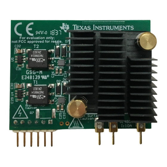
Page 6: Top Side View Of Lmg341Xevm-018
2.1.3 Bootstrap Mode The LMG341xEVM-018 card can be modified to operate in bootstrap mode, where the 12V bias voltage is used to power both LMG341xR050 devices. This can be achieved by removing U3, U4 and R2, and placing a 20 Ω resistor on R1, a 0 Ω resistor on R18 and a 600V SOD-123 diode on D1, such as Micro Commercial Components UFM15PL-TP. - Page 7 There is an option to disable PWM input to the FET card in the event of a fault signal from the LMG341xEVM-018. When the FAULT Protect jumper is placed in the EN mode PWM is disabled when either LMG341xR050 has an active fault. This disable is not latching, so when the fault clears PWM immediately resumes.
-
Page 8: Schematic
Schematic www.ti.com Schematic Figure 4. LMG3410EVM-018 Schematic Using the LMG341xEVM-018 half-bridge and LMG34XX-BB-EVM breakout SNOU165A – September 2018 – Revised March 2019 board EVM Submit Documentation Feedback Copyright © 2018–2019, Texas Instruments Incorporated... -
Page 9: Recommended Footprint For Lmg341Xevm-018
Schematic www.ti.com Figure 5. Recommended Footprint for LMG341xEVM-018 SNOU165A – September 2018 – Revised March 2019 Using the LMG341xEVM-018 half-bridge and LMG34XX-BB-EVM breakout board EVM Submit Documentation Feedback Copyright © 2018–2019, Texas Instruments Incorporated... -
Page 10: Lmg34Xx-Bb-Evm Schematic
PGND2 AGND ACMGND AGND2 Copyright © 2016, Texas Instruments Incorporated Figure 6. LMG34XX-BB-EVM Schematic Using the LMG341xEVM-018 half-bridge and LMG34XX-BB-EVM breakout SNOU165A – September 2018 – Revised March 2019 board EVM Submit Documentation Feedback Copyright © 2018–2019, Texas Instruments Incorporated... -
Page 11: Test Setup
Function Generator: Capable of 0 V to 5 V square wave output with adjustable duty cycle and frequency in desired operating range. It is recommended to operate the LMG341xEVM-018 and LMG34XX-BB-EVM with a switching frequency between 50 kHz to 200 kHz. -
Page 12: Recommended Connection Points
Figure 8. Recommended Connection Points PCB Notes: • Probe points for gate drive logic • 100 mil header for PWM input, PWM signals to LMG341xEVM-018 and FAULT output • BNC connector for PWM input • 12V bias supply input •... -
Page 13: Test Point Functional Description
Header to connect PWM, FAULT logic HB Card PIN Connector to interface LMG341xEVM-018 board SNOU165A – September 2018 – Revised March 2019 Using the LMG341xEVM-018 half-bridge and LMG34XX-BB-EVM breakout board EVM Submit Documentation Feedback Copyright © 2018–2019, Texas Instruments Incorporated... -
Page 14: Test Procedure
6 (PWM) and pin 5 (GND) at B. • Enable an external fan to direct airflow across the heatsink attached to the LMG341xEVM-018 Startup and Operating Procedure The following procedure is recommended to enable the LMG34XX-BB-EVM with the LMG341xEVM-018: 1. -
Page 15: Typical Characteristics
Figure 12. Switching Waveforms with 480V input, 100kHz, 30% duty cycle, 6A output Figure 11. Recommended Configuration for Heatsink and SNOU165A – September 2018 – Revised March 2019 Using the LMG341xEVM-018 half-bridge and LMG34XX-BB-EVM breakout board EVM Submit Documentation Feedback Copyright © 2018–2019, Texas Instruments Incorporated... -
Page 16: Evm Assembly Drawing And Pcb Layout
100kHz, 30% duty cycle, 6A output input, 100kHz, 30% duty cycle, 6A output EVM Assembly Drawing and PCB Layout Figure 16. LMG341xEVM-018 Inner Copper Layer 1 Figure 15. LMG341xEVM-018 Top Layer and Components Using the LMG341xEVM-018 half-bridge and LMG34XX-BB-EVM breakout SNOU165A –... -
Page 17: Lmg341Xevm-018 Inner Copper Layer
EVM Assembly Drawing and PCB Layout www.ti.com Figure 17. LMG341xEVM-018 Inner Copper Layer 2 Figure 18. LMG341xEVM-018 Bottom Layer and Components Figure 19. LMG34XX-BB-EVM Top Layer and Components Figure 20. LMG34XX-BB-EVM Bottom Layer and Components SNOU165A – September 2018 – Revised March 2019... -
Page 18: Bill Of Materials
U1, U3 High Speed, Robust EMC Reinforced ISO7731DBQR Texas Instruments Triple-Channel Digital Isolator, DBQ0016A (SSOP-16) Using the LMG341xEVM-018 half-bridge and LMG34XX-BB-EVM breakout SNOU165A – September 2018 – Revised March 2019 board EVM Submit Documentation Feedback Copyright © 2018–2019, Texas Instruments Incorporated... -
Page 19: Snou165A - September 2018 - Revised March 2019 Using The Lmg341Xevm-018 Half-Bridge And Lmg34Xx-Bb-Evm Breakout
Bill of Materials www.ti.com Table 5. LMG341xEVM-018 List of Materials (continued) Designator Description Part Number Manufacturer Single 2-Input Positive-AND Gate, SN74AHC1G08DBVR Texas Instruments DBV0005A (SOT-23-5) U4, U5 Low-Noise 1 A, 420 kHz Transformer SN6505BDBVR Texas Instruments Driver, DBV0006A (SOT-23-6) Diode, Ultrafast, 600 V, 1 A, SOD-123FL... -
Page 20: Lmg34Xx-Bb-Evm List Of Materials
SN74LVC2G08IDCTRQ1 Texas Instruments DCT0008A 1A Low Dropout Regulator, 4-pin SOT-223, LM2940IMP-5.0/NOPB Texas Instruments Pb-Free Using the LMG341xEVM-018 half-bridge and LMG34XX-BB-EVM breakout SNOU165A – September 2018 – Revised March 2019 board EVM Submit Documentation Feedback Copyright © 2018–2019, Texas Instruments Incorporated... - Page 21 NOTE: Page numbers for previous revisions may differ from page numbers in the current version. Changes from Original (September 2018) to A Revision ....................Page .................... • Updated UG covering both LMG341xR050 SNOU165A – September 2018 – Revised March 2019 Revision History Submit Documentation Feedback Copyright © 2018–2019, Texas Instruments Incorporated...
- Page 22 STANDARD TERMS FOR EVALUATION MODULES Delivery: TI delivers TI evaluation boards, kits, or modules, including any accompanying demonstration software, components, and/or documentation which may be provided together or separately (collectively, an “EVM” or “EVMs”) to the User (“User”) in accordance with the terms set forth herein.
- Page 23 www.ti.com Regulatory Notices: 3.1 United States 3.1.1 Notice applicable to EVMs not FCC-Approved: FCC NOTICE: This kit is designed to allow product developers to evaluate electronic components, circuitry, or software associated with the kit to determine whether to incorporate such items in a finished product and software developers to write software applications for use with the end product.
- Page 24 www.ti.com Concernant les EVMs avec antennes détachables Conformément à la réglementation d'Industrie Canada, le présent émetteur radio peut fonctionner avec une antenne d'un type et d'un gain maximal (ou inférieur) approuvé pour l'émetteur par Industrie Canada. Dans le but de réduire les risques de brouillage radioélectrique à...
- Page 25 www.ti.com EVM Use Restrictions and Warnings: 4.1 EVMS ARE NOT FOR USE IN FUNCTIONAL SAFETY AND/OR SAFETY CRITICAL EVALUATIONS, INCLUDING BUT NOT LIMITED TO EVALUATIONS OF LIFE SUPPORT APPLICATIONS. 4.2 User must read and apply the user guide and other available documentation provided by TI regarding the EVM prior to handling or using the EVM, including without limitation any warning or restriction notices.
- Page 26 Notwithstanding the foregoing, any judgment may be enforced in any United States or foreign court, and TI may seek injunctive relief in any United States or foreign court. Mailing Address: Texas Instruments, Post Office Box 655303, Dallas, Texas 75265 Copyright © 2019, Texas Instruments Incorporated...
- Page 27 TI products. TI’s provision of these resources does not expand or otherwise alter TI’s applicable warranties or warranty disclaimers for TI products. Mailing Address: Texas Instruments, Post Office Box 655303, Dallas, Texas 75265 Copyright © 2019, Texas Instruments Incorporated...
Need help?
Do you have a question about the LMG341xEVM-018 and is the answer not in the manual?
Questions and answers