Advertisement
Quick Links
www.ti.com
EVM User's Guide: LMG2656EVM-102
LMG2656 Half-Bridge Daughtercard Evaluation Module
Description
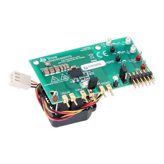
The LMG2656EVM-102 is designed to provide a
quick and easy platform to evaluate TI integrated
GaN devices in any half-bridge topology. The board
is designed to be interfaced with a larger system
using the 6 power pins and 12 digital pins on the
bottom edge of the board in a socket style external
connection. Power pins form the main switching loop
consisting of a high voltage DC bus, switch node, and
power ground. The digital pins control the LMG2656
device with PWM gate inputs, provide auxiliary power
with low voltage supplies, and report faults as a digital
output. Essential power stage and gate-driving, high-
frequency current loops are fully enclosed on the
board to minimize power loop parasitic inductance
for reducing voltage overshoots and improving
performance. Evaluating the LMG2656EVM-102
performance is most easily demonstrated using
a synchronous buck/boost motherboard from TI
(LMG342X-BB-EVM). The daughtercard easily plugs
into the motherboard and interfaces all power and
digital control in an open-loop configuration for full
system control. Additionally, a recommended footprint
SNOU209 – DECEMBER 2024
Submit Document Feedback
is provided to interface the daughtercard with a
custom system for further testing. Refer to the
LMG2656 data sheet before using this EVM.
Features
•
High-side gate-drive level shifter
•
Smart-switched bootstrap diode function: 0 QRR
•
Integrated lossless current sensing output
measurement
•
Low-side and high-side cycle-by-cycle overcurrent
protection and overtemperature protection
connected to output FAULT signal
•
Absolute maximum voltage rating of 650V
Applications
•
LLC or TPPFC for gaming, PoE, monitor PSU, PD
adapter
•
ACF, AHB for PD adapter, server aux
•
Motor drive inverter
motor
•
Inverter or
energy
•
Buck or boost converters
Copyright © 2024 Texas Instruments Incorporated
for hair dryer, vacuum, servo
micro-inverter
for solar, renewable
LMG2656 Half-Bridge Daughtercard Evaluation Module
Description
1
Advertisement

Related Manuals for Texas Instruments LMG2656


Summary of Contents for Texas Instruments LMG2656
- Page 1 DC bus, switch node, and • Low-side and high-side cycle-by-cycle overcurrent power ground. The digital pins control the LMG2656 protection and overtemperature protection device with PWM gate inputs, provide auxiliary power connected to output FAULT signal with low voltage supplies, and report faults as a digital •...
- Page 2 The LMG2656EVM-102 is configured for a socket style external connection for easy interface with external power stages to run the LMG2656 in various applications. Refer to the LMG2656 650V 250mΩ...
- Page 3 EVM from accidental touch in an adequate translucent plastic box with interlocks. • Limitation for Safe Use: – EVMs are not to be used as all or part of a production unit. SNOU209 – DECEMBER 2024 LMG2656 Half-Bridge Daughtercard Evaluation Module Submit Document Feedback Copyright © 2024 Texas Instruments Incorporated...
- Page 4 High Voltage! Electric shock is possible when connecting board to live wire. Board must be handled with care by a professional. For safety, use of isolated test equipment with overvoltage and overcurrent protection is highly recommended. LMG2656 Half-Bridge Daughtercard Evaluation Module SNOU209 – DECEMBER 2024 Submit Document Feedback...
- Page 5 2 Hardware 2.1 LMG2656EVM-102 Daughtercard The LMG2656EVM-102 has one LMG2656 device with two GaN FETs in a half-bridge configuration. All the bias and level shifting components are included, which allows low-side referenced signals to control both FETs. High-frequency decoupling capacitors are included on the power stage in an optimized layout to minimize parasitic inductance and reduce voltage overshoot.
- Page 6 Measurements for these digital signals can have reduced parasitics and ringing by moving the oscilloscope probe near the associated device pin. A tip and barrel method is most accurate, and removes any unexpected signal noise. LMG2656 Half-Bridge Daughtercard Evaluation Module SNOU209 – DECEMBER 2024 Submit Document Feedback...
- Page 7 To use the GDH pin as high-side input signal, INH must be grounded with jumper SH-J2. Move this jumper between pins 2 and 3 of header J3 to connect the INH pin of LMG2656 to AGND. Next, remove the jumper SH-J1 to expose header J2, which is now the input for high-side gate signal.
- Page 8 2.1.6 Heat Sink The heat sink is installed to help with heat dissipation of the LMG2656. Exposed copper pads are attached to the die attach pad (DAP) on the high-side and low-side devices to provide a low thermal impedance point for the heat sink.
- Page 9 2.2.1 Bias Supply The motherboard requires one 12V bias supply. A buck regulator (in LMG342X-BB-EVM) steps the voltage down to a tightly regulated 5V for the logic and auxiliary power of the LMG2656 when the LMG2656EVM-102 is configured in isolated power mode.
- Page 10 Fan: For the heat-sink-version EVM daughtercard, a dedicated cooling fan is attached on the back side of the heat sink. Please make sure the fan is powered by the 12V power supply before test. LMG2656 Half-Bridge Daughtercard Evaluation Module SNOU209 – DECEMBER 2024 Submit Document Feedback Copyright ©...
- Page 11 12. Provide 12V bias supply to fan by connecting the 3-pin power cord from fan to J15. Figure 2-5. LMG342X-BB-EVM Motherboard With LMG2656EVM-102 SNOU209 – DECEMBER 2024 LMG2656 Half-Bridge Daughtercard Evaluation Module Submit Document Feedback Copyright © 2024 Texas Instruments Incorporated...
- Page 12 (up to 480V). As the voltage is ramping up, the HV LED turns on and become brighter. Figure 2-7. Switch-Node Voltage Measurement with High-Bandwidth Probe and Pigtail Ground Connection LMG2656 Half-Bridge Daughtercard Evaluation Module SNOU209 – DECEMBER 2024 Submit Document Feedback...
- Page 13 EMI performance when designing. Figure 2-8. 80V/ns at 400V/1A SNOU209 – DECEMBER 2024 LMG2656 Half-Bridge Daughtercard Evaluation Module Submit Document Feedback Copyright © 2024 Texas Instruments Incorporated...
- Page 14 • Fault protection on the LMG342X-BB-EVM is not latching, therefore PWM resumes if a fault clears and the LMG342X-BB- EVM is still operational. LMG2656 Half-Bridge Daughtercard Evaluation Module SNOU209 – DECEMBER 2024 Submit Document Feedback Copyright © 2024 Texas Instruments Incorporated...
- Page 15 Hardware Design Files 3 Hardware Design Files 3.1 LMG2656EVM-102 Schematic Figure 3-1. LMG2656EVM-102 Schematic SNOU209 – DECEMBER 2024 LMG2656 Half-Bridge Daughtercard Evaluation Module Submit Document Feedback Copyright © 2024 Texas Instruments Incorporated...
- Page 16 150uF 0395443002 0.1uF 0.1uF PGND5 PGND PGND AGND AGND AGND AGND1 PGND4 PGND 3267 PGND1 PGND PGND2 PGND Figure 3-2. LMG342X-BB-EVM Schematic LMG2656 Half-Bridge Daughtercard Evaluation Module SNOU209 – DECEMBER 2024 Submit Document Feedback Copyright © 2024 Texas Instruments Incorporated...
- Page 17 The PCB layers for this EVM are illustrated in Figure 3-3 through Figure 3-6. Figure 3-3. Top Layer Figure 3-4. Layer 2 SNOU209 – DECEMBER 2024 LMG2656 Half-Bridge Daughtercard Evaluation Module Submit Document Feedback Copyright © 2024 Texas Instruments Incorporated...
- Page 18 Hardware Design Files www.ti.com Figure 3-5. Layer 3 Figure 3-6. Bottom Layer LMG2656 Half-Bridge Daughtercard Evaluation Module SNOU209 – DECEMBER 2024 Submit Document Feedback Copyright © 2024 Texas Instruments Incorporated...
- Page 19 TP11 Test Point, SMT S2751-46R TP13, TP14, TP15, TP16, TP17, TP18 PCB Pin, 0.04" DIA, Edge-Mount 3621-0-32-15-00-00-08-0 Integrated 650V GaN Half-Bridge LMG2656 SNOU209 – DECEMBER 2024 LMG2656 Half-Bridge Daughtercard Evaluation Module Submit Document Feedback Copyright © 2024 Texas Instruments Incorporated...
- Page 20 RES, 0, 5%, 0.1 W, AEC-Q200 Grade 0, 0603 CRCW06030000Z0EA R3, R15 Trimmer, 5 K, 0.25 W, SMD 3224X-1-502E R6, R22 RES, 100 k, 5%, 0.1 W, 0603 CRCW0603100KJNEAC LMG2656 Half-Bridge Daughtercard Evaluation Module SNOU209 – DECEMBER 2024 Submit Document Feedback Copyright © 2024 Texas Instruments Incorporated...
- Page 21 Triple Schmitt-Trigger Inverter, DCU0008A (VSSOP-8) SN74LVC3G14DCUTG4 1A SIMPLE SWITCHER® Power Module with 20V Maximum Input LMZ12001EXTTZ/NOPB Voltage for Military and Rugged Applications, 7 pin TO-PMOD SNOU209 – DECEMBER 2024 LMG2656 Half-Bridge Daughtercard Evaluation Module Submit Document Feedback Copyright © 2024 Texas Instruments Incorporated...
- Page 22 4.1 Trademarks All trademarks are the property of their respective owners. 5 Related Documentation • Texas Instruments, LMG2656 Integrated 650V GaN Half Bridge, data sheet • Texas Instruments, Thermal Performance of QFN 12x12 Package for 600V GaN Power Stage, application note •...
- Page 23 STANDARD TERMS FOR EVALUATION MODULES Delivery: TI delivers TI evaluation boards, kits, or modules, including any accompanying demonstration software, components, and/or documentation which may be provided together or separately (collectively, an “EVM” or “EVMs”) to the User (“User”) in accordance with the terms set forth herein.
- Page 24 www.ti.com Regulatory Notices: 3.1 United States 3.1.1 Notice applicable to EVMs not FCC-Approved: FCC NOTICE: This kit is designed to allow product developers to evaluate electronic components, circuitry, or software associated with the kit to determine whether to incorporate such items in a finished product and software developers to write software applications for use with the end product.
- Page 25 www.ti.com Concernant les EVMs avec antennes détachables Conformément à la réglementation d'Industrie Canada, le présent émetteur radio peut fonctionner avec une antenne d'un type et d'un gain maximal (ou inférieur) approuvé pour l'émetteur par Industrie Canada. Dans le but de réduire les risques de brouillage radioélectrique à...
- Page 26 www.ti.com EVM Use Restrictions and Warnings: 4.1 EVMS ARE NOT FOR USE IN FUNCTIONAL SAFETY AND/OR SAFETY CRITICAL EVALUATIONS, INCLUDING BUT NOT LIMITED TO EVALUATIONS OF LIFE SUPPORT APPLICATIONS. 4.2 User must read and apply the user guide and other available documentation provided by TI regarding the EVM prior to handling or using the EVM, including without limitation any warning or restriction notices.
- Page 27 Notwithstanding the foregoing, any judgment may be enforced in any United States or foreign court, and TI may seek injunctive relief in any United States or foreign court. Mailing Address: Texas Instruments, Post Office Box 655303, Dallas, Texas 75265 Copyright © 2023, Texas Instruments Incorporated...
- Page 28 TI products. TI’s provision of these resources does not expand or otherwise alter TI’s applicable warranties or warranty disclaimers for TI products. TI objects to and rejects any additional or different terms you may have proposed. IMPORTANT NOTICE Mailing Address: Texas Instruments, Post Office Box 655303, Dallas, Texas 75265 Copyright © 2024, Texas Instruments Incorporated...
Need help?
Do you have a question about the LMG2656 and is the answer not in the manual?
Questions and answers