Table of Contents
Advertisement
Quick Links
The LMG3410EVM-031 features two LMG3410R150 600V GaN power transistors with integrated drivers
that are configured in a half bridge with all the required bias circuit and logic/power level shifting. Essential
power stage and gate driving high frequency current loops are fully enclosed on the board to minimize
parasitic inductances, reducing voltage overshoots and improving performance. The LMG3410EVM-031 is
configured to have a socket style external connection for easy interface with external power stages to run
the LMG3410R150 in various applications.
1
....................................................................................................................
2
.....................................................................................................................
3
...................................................................................................................
4
5
6
7
EVM Assembly Drawing and PCB Layout
8
Bill of Materials
1
Simplified LMG3410EVM-031 Schematic
2
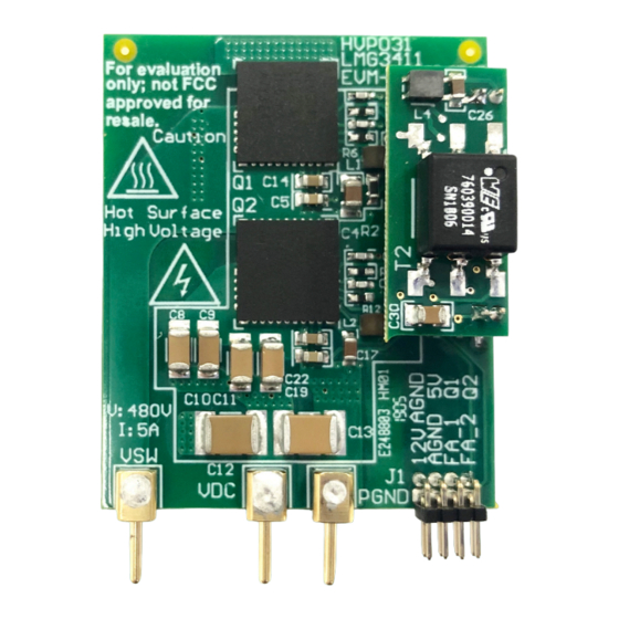
Top Side View of LMG3410EVM-031
3
Back Side View of LMG3410EVM-031
4
Top Side View of LMG3410EVM-031 in Isolated Power Supply Configuration
5
Back Side View of LMG3410EVM-031 in Isolated Power Supply Configuration
6
LMG3410EVM-031 Schematic
7
Recommended Footprint for LMG3410EVM-031
8
LMG34XX-BB-EVM Schematic
9
LMG3410EVM-031 Connected with LMG34XX-BB-EVM
10
Recommended Connection Points
11
12
13
14
15
16
17
18
19
20
21
22
SNOU168 - June 2019
Submit Documentation Feedback
LMG3410R150-031 EVM User Guide
.............................................................................................................
.....................................................................................................
..............................................................................
.............................................................................................................
................................................................................
.....................................................................................
...................................................................................
.............................................................................................
..........................................................................................
.......................................................................................
..............................................................................
..............................................................................
Copyright © 2019, Texas Instruments Incorporated
Contents
List of Figures
......................................................................
............................................................
..................................................................
...................................................
...................................................................
......................................................................
..................................................................
......................................................................
..................................................................
LMG3410R150-031 EVM User Guide
User's Guide
SNOU168 - June 2019
..................
.....................................
....................................
.....................................
.......................
.......................
3
5
9
12
15
16
18
21
5
6
6
7
7
9
10
11
12
13
16
16
16
16
16
16
18
18
19
19
20
20
1
Advertisement
Table of Contents

Related Manuals for Texas Instruments LMG3410EVM-031


Summary of Contents for Texas Instruments LMG3410EVM-031
-
Page 1: Table Of Contents
SNOU168 – June 2019 LMG3410R150-031 EVM User Guide The LMG3410EVM-031 features two LMG3410R150 600V GaN power transistors with integrated drivers that are configured in a half bridge with all the required bias circuit and logic/power level shifting. Essential power stage and gate driving high frequency current loops are fully enclosed on the board to minimize parasitic inductances, reducing voltage overshoots and improving performance. - Page 2 List of Terminals ..................LMG3410EVM-031 List of Materials ..................LMG34XX-BB-EVM List of Materials Trademarks All trademarks are the property of their respective owners. LMG3410R150-031 EVM User Guide SNOU168 – June 2019 Submit Documentation Feedback Copyright © 2019, Texas Instruments Incorporated...
-
Page 3: Lmg3410Evm-031 User's Guide General Ti High Voltage Evaluation User Safety Guidelines
Any other use and/or application are strictly prohibited by Texas Instruments. If you are not suitably qualified, you must immediately stop from further use of the HV EVM. - Page 4 LMG3410EVM-031 User's Guide General TI High Voltage Evaluation User Safety Guidelines www.ti.com Safety and Precautions The EVM is designed for professionals who have received the appropriate technical training, and is designed to operate from an AC power supply or a high-voltage DC supply. Please read this user guide and the safety-related documents that come with the EVM package before operating this EVM.
-
Page 5: Description
Description www.ti.com Description The LMG3410EVM-031 operates as a daughter card as part of a larger custom designed system or with the LMG34XX-BB-EVM breakout motherboard. LMG3410EVM-031 The LMG3410EVM-031 configures two LMG3410R150 GaN FETs in a half bridge. All the bias and level shifting components are included, allowing low side referenced signals to control both FETs. - Page 6 Figure 5. To disconnect from the boostrap mode, D1 and R2 needs to be removed. Do NOT power up the LMG3410EVM-031 when R1, R2 and D1 are all populated with the isolated power supply board connected. 2.1.5 Heatsink The heatsink is installed to help with heat dissipation of the LMG3410R150.
- Page 7 Main board Figure 3. Back Side View of LMG3410EVM-031 Figure 2. Top Side View of LMG3410EVM-031 Figure 4. Top Side View of LMG3410EVM-031 in Isolated Power Supply Configuration Figure 5. Back Side View of LMG3410EVM-031 in Isolated Power Supply Configuration SNOU168 –...
- Page 8 12V input is used to power the two LMG3410R150 devices. A linear drop off regulator steps the voltage down to a tightly regulated 5V for logic power of the LMG3410R150. When the LMG3410EVM-031 is configured in isolated power supply mode the 5V is also used for auxiliary power for the top LMG3410R150 Q1.
-
Page 9: Schematic
4.7uF IN Pin on daughter board 0.1uF 4.7uF OUT Pin on daughter board 4.7uF -ISO_RET_H_AO AGND_AI SN6505 DIODE_SCHOTTKY ISO_RET_H_B Figure 6. LMG3410EVM-031 Schematic SNOU168 – June 2019 LMG3410R150-031 EVM User Guide Submit Documentation Feedback Copyright © 2019, Texas Instruments Incorporated... - Page 10 Schematic www.ti.com Figure 7. Recommended Footprint for LMG3410EVM-031 LMG3410R150-031 EVM User Guide SNOU168 – June 2019 Submit Documentation Feedback Copyright © 2019, Texas Instruments Incorporated...
- Page 11 1µF 10µF 47µH 282834-2 AGND1 AGND PGND PGND Green PGND2 AGND ACMGND AGND2 Copyright © 2016, Texas Instruments Incorporated Figure 8. LMG34XX-BB-EVM Schematic SNOU168 – June 2019 LMG3410R150-031 EVM User Guide Submit Documentation Feedback Copyright © 2019, Texas Instruments Incorporated...
-
Page 12: Test Setup
DC Load: Capable of 600 V operation at up to 5 A in current-mode operation. Fan: 200 LFM minimum airflow is recommended. Recommended Test Setup The LMG3410EVM-031 connects to the LMG34XX-BB-EVM as Figure 9 shows. Figure 9. LMG3410EVM-031 Connected with LMG34XX-BB-EVM LMG3410R150-031 EVM User Guide SNOU168 –... - Page 13 To minimize the risk of the electrical shock and burn hazard, precautions must be taken when handling the board due to the high voltages and elevated temperatures on the EVM. SNOU168 – June 2019 LMG3410R150-031 EVM User Guide Submit Documentation Feedback Copyright © 2019, Texas Instruments Incorporated...
-
Page 14: Test Point Functional Description
Single 0 V to 5 V PWM input for gate LOGIC Header to connect PWM, FAULT logic HB Card PIN Connector to interface LMG3410EVM-031 board LMG3410R150-031 EVM User Guide SNOU168 – June 2019 Submit Documentation Feedback Copyright © 2019, Texas Instruments Incorporated... -
Page 15: Test Procedure
Test Procedure www.ti.com Test Procedure Setup The following procedure is recommended to set up the LMG34XX-BB-EVM with the LMG3410EVM-031: • Connect LMG3431EVM-018 to LMG34XX-BB-EVM. • Connect oscilloscope or multimeter probes to desired test points as shown in A or G. -
Page 16: Typical Characteristics
Voltage Switch Node Figure 14. Switching Waveforms with 400V Input, 100kHz, 30% Duty Cycle, 4A Output Figure 13. Recommended Configuration for Heatsink and LMG3410R150-031 EVM User Guide SNOU168 – June 2019 Submit Documentation Feedback Copyright © 2019, Texas Instruments Incorporated... -
Page 17: Low To High Transition Waveform With 400V Input, 100Khz, 30% Duty Cycle, 4A Output
Figure 15. Low to High Transition Waveform with 400V Input, 100kHz, 30% Duty Cycle, 4A Output Input, 100kHz, 30% Duty Cycle, 4A Output SNOU168 – June 2019 LMG3410R150-031 EVM User Guide Submit Documentation Feedback Copyright © 2019, Texas Instruments Incorporated... -
Page 18: Lmg3410Evm-031 Top Layer And Components
EVM Assembly Drawing and PCB Layout www.ti.com EVM Assembly Drawing and PCB Layout Figure 17. LMG3410EVM-031 Top Layer and Components Figure 18. LMG3410EVM-031 Inner Copper Layer 1 LMG3410R150-031 EVM User Guide SNOU168 – June 2019 Submit Documentation Feedback Copyright © 2019, Texas Instruments Incorporated... -
Page 19: Lmg3410Evm-031 Inner Copper Layer 2
EVM Assembly Drawing and PCB Layout www.ti.com Figure 19. LMG3410EVM-031 Inner Copper Layer 2 Figure 20. LMG3410EVM-031 Bottom Layer and Components SNOU168 – June 2019 LMG3410R150-031 EVM User Guide Submit Documentation Feedback Copyright © 2019, Texas Instruments Incorporated... -
Page 20: Lmg34Xx-Bb-Evm Top Layer And Components
EVM Assembly Drawing and PCB Layout www.ti.com Figure 21. LMG34XX-BB-EVM Top Layer and Components Figure 22. LMG34XX-BB-EVM Bottom Layer and Components LMG3410R150-031 EVM User Guide SNOU168 – June 2019 Submit Documentation Feedback Copyright © 2019, Texas Instruments Incorporated... -
Page 21: Lmg3410Evm-031 List Of Materials
Bill of Materials www.ti.com Bill of Materials Table 5. LMG3410EVM-031 List of Materials QTY DESIGNATOR DESCRIPTION PART NUMBER MANUFACTURER CAP, CERM, 1 uF, 16 V, +/- 10%, X5R, 0402 EMK105BJ105KVHF Taiyo Yuden C2, C20 CAP, CERM, 0.1 uF, 50 V, +/- 10%, X7R, 0402... -
Page 22: Lmg34Xx-Bb-Evm List Of Materials
Dual Schmitt-Trigger Inverter, DCK0006A SN74LVC2G14DCKR Texas Instruments Dual 2-input Positive-and Gate, DCT0008A SN74LVC2G08IDCTRQ1 Texas Instruments 1A Low Dropout Regulator, 4-pin SOT-223, LM2940IMP-5.0/NOPB Texas Instruments Pb-Free LMG3410R150-031 EVM User Guide SNOU168 – June 2019 Submit Documentation Feedback Copyright © 2019, Texas Instruments Incorporated... - Page 23 TI products. TI’s provision of these resources does not expand or otherwise alter TI’s applicable warranties or warranty disclaimers for TI products. TI objects to and rejects any additional or different terms you may have proposed. IMPORTANT NOTICE Mailing Address: Texas Instruments, Post Office Box 655303, Dallas, Texas 75265 Copyright © 2022, Texas Instruments Incorporated...
Need help?
Do you have a question about the LMG3410EVM-031 and is the answer not in the manual?
Questions and answers