Table of Contents
Advertisement
Advertisement
Table of Contents
Troubleshooting

Related Manuals for Zimmer A.T.S. 2000


Summary of Contents for Zimmer A.T.S. 2000
- Page 1 Operator & Service Manual A.T.S. 2000 ™ TOURNIQUET SYSTEM REF 60-2000-101-00...
- Page 2 ™ ranty period, Zimmer will repair or replace, at its option, any product which is defective in materials or workmanship or which fails to meet the published specification for that model. This Limited Warranty is made only to the original purchaser of the product and is non-transferable.
-
Page 3: Table Of Contents
TABLE OF CONTENTS A.T.S. 2000 TOURNIQUET SYSTEM SECTION TITLE PAGE GENERAL INFORMATION Features ..................3 Specifications ................3 Intended Use ................4 Contraindications ..............4 Precautions in Use ..............4 Adverse Effects ................5 INSTALLATION AND OPERATING INSTRUCTIONS Initial Inspection ................. 5 Functional and Calibration Check .......... - Page 4 SECTION TITLE PAGE Troubleshooting Guide ............14 Replacement Parts ..............18 Storage ................... 20 FIGURE TITLE PAGE Main and Second Calibration Setup Assembly ......21 Controls, Indicators & Connectors .......... 22 Block Diagram ................. 23 4–7 Removing Chassis From Rear Case ........24 8–10 Separating Chassis ..............
-
Page 5: General Information
*U.S. Patents B1 4,469,099; 4,548,198; 5,556,415; 5,607,447; 5,855,589 AC Indicator Light: 1.1 FEATURES Green LED Battery Type: The A.T.S. 2000 Tourniquet System is an automatic, micro- processor-based pneumatic tourniquet system. Its features 2 Rechargeable, 12 V sealed lead acid, 2.3 Amp hours include: Battery Discharge Time: •... -
Page 6: Intended Use
• Do not use an elastic bandage for exsanguination in The A.T.S. 2000 Tourniquet System is intended to be used cases where this will cause bacteria, exotoxins, or ma- by qualified medical professionals to temporarily occlude lignant cells to spread to the general circulation, or blood flow in a patient’s extremities during surgical proce-... -
Page 7: Adverse Effects
If the unit is damaged, notify the carrier and your Zimmer to undesired pressure distribution on the limb. The representative immediately. If the initial inspection results... -
Page 8: Installation
The A.T.S. 2000 Tourniquet is designed to be mounted on a) Set the unit to STANDBY by pressing and holding a table top or tourniquet stand (REF 60-4022-001). The the ON/STANDBY (I/O) touch-switch. -
Page 9: Volume Selection
STANDBY. seconds by depressing this switch. The push-button will Note: During STANDBY, power to the A.T.S. 2000 in- remain lighted until the alarm condition is corrected. strument and all instrument functions (i.e. inflation,... -
Page 10: Single Cuff Operation
In many operating rooms, it is customary to prominently note the time or more during power-up, the A.T.S. 2000 Tourni- of inflation, and to warn the surgeon after a certain quet will declare it an abnormal start-up sequence. -
Page 11: Dual Cuff Operation
2.8 ALARM CONDITIONS 10. Set the unit to STANDBY by pressing and holding the ON/STANDBY touch-switch. This switch has There are a number of conditions for which the A.T.S. approximately a 2-second delay before allowing 2000 Tourniquet will produce a visual and/or audible alarm. the unit to be set to STANDBY. -
Page 12: Alarm Conditions
PITCH overshoot, or hose occlusion. This condition, for an extended period, would indicate a hardware failure and the A.T.S. 2000 should be replaced. CUFF SIDE LEAK: STEADY LEAK A substantial leak has been present for A sustained leak exists that HIGH more than 9 seconds. -
Page 13: Hardware Malfunction Codes
Table 2.2 Hardware Malfunction Codes PRESSURE TIME AUDIBLE TONE ALARM MEANING OF INDICATIONS DISPLAY DISPLAY SILENCE LIGHT FAIL STEADY HIGH AMPLIFIER OUT OF RANGE. PITCH BAT LOW PLUG IN STEADY HIGH BATTERY VOLTAGE TOO LOW TO PITCH ENSURE RELIABLE OPERATION. FAIL STEADY HIGH BATTERY DEFECTIVE OR TOO LOW TO... -
Page 14: Maintenance
SITIVE. TAKE APPROPRIATE PRECAUTIONS WHEN 3.1 GENERAL MAINTENANCE INFORMATION SERVICING THESE BOARDS. While the A.T.S. 2000 Tourniquet has been designed and To gain access to all internal parts, first remove the four manufactured to high industry standards, it is recommend- rubber feet from the bottom of the unit. -
Page 15: Calibration
Section 2.2, connect two 24 in. (61 cm) (or larger) cuffs main cuff “INFLATE” and “DEFLATE” touch-switches which are known to be leak free to the A.T.S. 2000 Tourni- at the same time. A tone will be heard letting you know quet System. -
Page 16: Battery Voltage And Battery Service
It is recommended that the batteries in the A.T.S. 2000 be replaced annually. The A.T.S. 2000 should be connected to ~ power 24 hours before initial use. -
Page 17: Expected Test Point Readings
Table 3.1 Expected Test Point Readings Power Su pp l y Normal Reading Tolerance Conditions/Comments Board Common +/-50 mV Bulk Supply Common +27 V +/-2 V Main supply for entire system CPU Board Normal Reading Tolerance Conditions/Comments +/-2 V Main supply for entire system +27 V +26 V... -
Page 18: Troubleshooting
Table 3.2 Troubleshooting Expected reading on the CPU and Power Supply boards are shown in Table 3.1. The measurements are to be made To aid in unscheduled maintenance, the following list at room temperature with the cuffs disconnected, and the delineates a number of possible malfunctions that could unit plugged in. - Page 19 Table 3.2 Troubleshooting (continued) SYMPTOM POSSIBLE CAUSES CHECK TEST POINTS 8. Unit turns on and gives tones a) Faulty 5 V display voltage (+V) TP11 (Power Supply Board) but no displays are present. 9. “AMP” “FAIL” at start up. a) Faulty 15 V supply. TP25 (CPU Board) b) Faulty A to D supply voltage.
-
Page 20: Replacement Parts
3.8 REPLACEMENT PARTS You can also contact your local Zimmer distributor. To en- sure prompt service, please include the following informa- The following is a list of field replacement parts that can be tion with your order: ordered from Zimmer. To obtain parts or additional informa-... - Page 21 Recommended Accessories and Kits Description 60-2000-102 A.T.S. 2000 Tourniquet System (with A.T.S. Cylindrical Cuffs) with Hoses 60-2000-103 A.T.S. 2000 Tourniquet System (with A.T.S. Cylindrical Cuffs) with Hoses, Tourniquet Stand and Basket 60-2000-104 A.T.S. Tourniquet System (without Cuffs) with Hoses, Tourniquet Stand...
-
Page 22: Storage
60-4018-001 A.T.S. Dual Hose, Red/White A.T.S. Dual Hose, Red/White 3.9 STORAGE The A.T.S. 2000 Tourniquet System has an operating tem- perature range of 50°F to 100°F (10°C to 38°C). The following are environmental conditions for transporta- tion and storage: A. Ambient temperature range 1°F to 149°F (–17°C to 65°C) B. -
Page 23: Main And Second Calibration Setup Assembly
Main and Second Calibration Setup Assembly A. Reservoir Sense Ports B. Main Cuff Sense Port C. Second Cuff Sense Port D. Calibration Hose Assembly E. Calibrated mmHg Pressure Meter minimum range of 0 to 700 mmHg F. Pressure Regulator 0 to 700 mmHg minimum G. -
Page 24: Controls, Indicators & Connectors
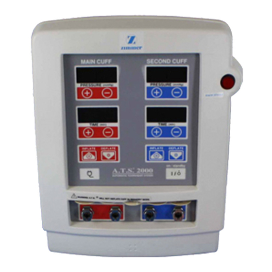
Controls, Indicators & Connectors A. ON/STANDBY (I/O) Touch-Switch B. PRESSURE SETTING Touch-Switches C. TIME SETTING Touch-Switches D. INFLATE/DEFLATE Touch-Switches E. ALARM SILENCE Switch F. PRESSURE Displays G. TIME Displays H. AC Indicator Light I. Quick Reference Cards J. Cuff Connectors K. -
Page 25: Block Diagram
Block Diagram... -
Page 26: Removing Chassis From Rear Case
Removing Chassis from Rear Case Removing Chassis from Rear Case 1. Remove Pole Clamp knob 2. Remove Rear Cover Screws Removing Chassis from Rear Case Removing Chassis from Rear Case 3. Remove 4 Feet and Screws 4. Slide Front and Rear Covers Apart... -
Page 27: Separating Chassis
Separating Chassis Separating Chassis 2. Remove Recessed Bottom 3 screws 1. Remove top 2 screws Separating Chassis 3. Access to all components... -
Page 28: Cpu Board
CPU Board... -
Page 29: Power Supply Board
Power Supply Board... -
Page 30: Warnings, Cautions, And Symbol Definitions
Warnings, Cautions, and Symbol Definitions (See Fig. 17.) Power “OFF” for a part of equipment Power “ON” connected to the mains Type B equipment Alternating Current Protective earth ground Direct Current Refer to instruction manual Electrical Hazard Year of manufacture Replace fuse as marked Conformity Marking of the Council of the European Community (TÜV Product Service,... - Page 31 MEDICAL EQUIPMENT WITH RESPECT TO ELECTRIC SHOCK, FIRE, AND MECHANICAL HAZARDS ONLY, IN ACCORDANCE WITH UL 60601-1, CAN/CSA C22.2 NO. 601.1, AND IEC 60601-1 Label 62-8000-025-00 ® WARNING: A.T.S. WILL NOT DEFLATE CUFF IN “STANDBY” MODE. Warnings, Cautions, and Symbol Definitions...
- Page 32 Revised: 02-05 Zimmer Orthopaedic Surgical Products © 1996, 2005 Zimmer Orthopaedic Surgical Products 200 West Ohio Avenue Printed in U.S.A. P.O. Box 10 62-2000-101-00 Dover, Ohio U.S.A. 44622...
Need help?
Do you have a question about the A.T.S. 2000 and is the answer not in the manual?
Questions and answers