Kval Edge-SS System Operation Manual
Hide thumbs
Also See for Edge-SS System:
- Operation & service manual (180 pages) ,
- Service manual (107 pages) ,
- Quick start (2 pages)

Subscribe to Our Youtube Channel
Related Manuals for Kval Edge-SS System


Summary of Contents for Kval Edge-SS System
- Page 1 Operation Manual Published: October 14, 2020 Innovation, Quality & Honesty Edge-SS System...
- Page 2 6:30 AM to 1:30 PM Pacific Standard Time, Friday Parts & Service Sales: 6:30 AM to 4:00 PM Pacific Standard Time, Monday through Thursday 6:30 AM to 1:30 PM Pacific Standard Time, Friday (Other sales related inquiries: http://www.inc.com) • Email: service@inc.com KVAL Edge-SS System Operation Manual...
- Page 3 KVAL Edge-SS System Operation Manual Your Feedback is Welcome: To help us design products that make your job easier and your business more successful, we'd like to gain your perspective about your user experience with our product - that is, the manual, the machinery, the software, etc.
- Page 4 KVAL Edge-SS System Operation Manual...
- Page 5 Licensor retains all ownership of the KvalCAM Software. Title, ownership rights, and intellectual property rights in the KvalCAM Software shall remain with, Inc. The Kval- CAM Software is protected by copyright laws and treaties. Title and related rights in the content generated through the KvalCAM Software are also the property of the Licensor and are protected by applicable law.
- Page 6 KVAL Edge-SS System Operation Manual...
-
Page 7: Table Of Contents
Table of Contents Introduction to the Edge-SS System Chapter 1 Overview of the Edge-SS System ........... 1-2 About this Manual .................1-4 Safety First!................1-5 Safety Sheet Sign-Off Sheet..............1-5 Safety Terminology of Labels..............1-5 Safety Guidelines..................1-5 Lockout-Tagout Guidelines ............1-9 Follow the P-R-O-P-E-R lockout rule of thumb........1-9 Lockout Tagout Procedure............ - Page 8 About Backing up Data and Checking the Revision Status ..2-30 Job Preview Examples ............2-31 Door Face (Lock Preview) ..............2-31 Door Edge (Lock Preview)..............2-32 Door Edge (Hinge Preview) ..............2-33 About Validation............... 2-34 About the Validation Screen ...............2-35 Outline ....................2-36 KVAL Edge-SS Manual...
- Page 9 The Machine Start Summary ........... 3-8 Summary of the KvalCAM Interface ........3-11 Libraries and Machine Line Screens ..........3-11 Machine Control and Calibration Screens ..........3-11 Status and Log Screens..............3-12 About Machine Status Feedback ..........3-13 About the Edge-SS Interface Screens........3-14 KVAL Edge-SS Manual...
- Page 10 About Restore Points................4-6 About the Edge-SS Calibration Screen ........4-7 Edge-SS Calibration Screen..............4-7 Calibrating the Feelers............. 4-8 Identify the Hinge and Lock Head Designations........4-9 Using the Carriage Axes Calibrations...........4-9 About Tools Calibration...............4-10 Tool Slot Identification.................4-11 Chisel Locations .................4-12 KVAL Edge-SS Manual...
- Page 11 Typical Valve Bank Controls ...............5-16 About the Electrical Panels............5-17 Main Electrical Panel ................5-17 The High Frequency Panel ..............5-18 About the Nodes ..............5-19 Typical Block Diagram of Network Connections .........5-19 Graphical Sample of Node Connections and Power Distribution ..5-20 KVAL Edge-SS Manual...
- Page 12 Table of Contents KVAL Edge-SS Manual...
- Page 13 CHAPTER 1 Introduction to the Edge-SS System Chapter 1 at a Glance The following information is available in this chapter: Summary of Chapter TABLE 1- 1. Section Name Summary Page This section provides an overview of the page 1-2 Overview of the Edge-SS machine.
-
Page 14: Overview Of The Edge-Ss System
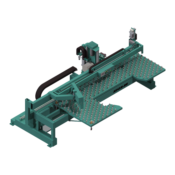
Overview of the Edge-SS System Overview of the Edge-SS System is a computer-controlled router designed to machine architectural doors for Edge Edge-SS Cuts. Many customers also use the Edge for re-railing & re-stiling operations Examples of diverse cuts: • hinge pockets •... - Page 15 Overview of the Edge-SS System nected to a solid state motion controller. The computer allows an almost limitless number of routing patterns to be stored for instantaneous set-up. Edge: Programming has been developed to automatically generate the most common CNC pro- gramming with graphics screens.
-
Page 16: About This Manual
Overview of the Edge-SS System About this Manual This manual is part of a package delivered with the machine line. Integration Package includes the following: includes the following: Operation Manual Chapter Title Description Introduction Descriptions of Machine Line and Safety Information. -
Page 17: Safety First
Training Ensure that all employees who operate this machine are aware of and adhere to all safety precautions posted on the machine and are trained to operate this machine in a safe manner. KVAL Operation Manual... - Page 18 All cylinders on machine are under high pressure and can be very dangerous when activated. Before performing any mainte- nance or repairs on this machine turn off the main air disconnect. Lockout and tagout this connection. See “Lockout Tagout Procedure” on page 1-10. KVAL Operation Manual...
- Page 19 This should be done in accordance with applicable state and/or federal code requirements. Laser Warnings On some machines, laser indicators are used to set boundaries. Follow the manufacturers safety precautions. KVAL Operation Manual...
- Page 20 Follow Your Company’s Safety Procedures In addition to these safety guidelines. Your company should have on-site and machine specific safety proce- dures to follow. KVAL Operation Manual...
-
Page 21: Lockout-Tagout Guidelines
O..OFF! Shut off all power sources and isolating devices P..Place lock and tag E..ENERGY: Release stored energy to a zero-energy state R ..Recheck controls and test to ensure they are in the “OFF” state KVAL Operation Manual... -
Page 22: Lockout Tagout Procedure
Turn Switch to the Lock and Tag out Insert Lock into hole. OFF position Note: When multiple people are working on the machine, each person needs to have a lock on the handle in the extra holes provided. KVAL Operation Manual 1-10... -
Page 23: Lockout Tagout Air Supply
The lock and tag can now be removed (only by the person(s) who placed them), and the machine can be re-energized. The tags must be destroyed and the locks and keys returned to the lockout center. KVAL Operation Manual 1-11... -
Page 24: Zero-Energy To Start-Up
Service team. See “Getting Help from KVAL KVAL” on page 1-14. Check Controls Confirm that all switches are in the “OFF” position. Please be advised that some com- ponents of the machine may start automatically when energy is restored. - Page 25 Be sure to follow the P-R-O- P-E-R lockout/tagout procedures, and that those around you do also. Close the Cage Gate Verify all cage gates are securely closed. Ensure all safety protocols are in effect. KVAL Operation Manual 1-13...
-
Page 26: Getting Help From Kval
Getting Help from KVAL Getting Help from KVAL Before you seek help, first try the troubleshooting procedures. Follow the procedures below. If you are unable to resolve the problem: Locate the machine’s Specification Plate and record the serial number, 3 phase volts, electrical print number, and air print number. -
Page 27: Kval Return And Warranty Policy
KVAL Return and Warranty Policy KVAL Return and Warranty Policy KVAL's goal is to provide customers with high quality products. If, for any reason, you are not completely satisfied with your purchase, please contact us at: Email: parts@kvalinc.com +1 (800) 553-5825 Phone: •... -
Page 28: Customer Errors
Kval provides a warranty to products that are deemed defective. Within 30 days of discovery of said defect, please notify Kval, but no more than one (1) year after delivery will the product be covered under Warranty. The repair, replacement, or payment in the manner described above shall be the exclusive remedy of Buyer for breach of Kval’s warranty or for claims based upon failure... -
Page 29: How To Download The Service Application
KVAL tab. Follow the instruc- Support tions on the Support web page. Click the Download button to download the application that allows the technician to KVAL have access to the operator sta- tion. KVAL Operation Manual 1-17... - Page 30 Sample of i.e Explorer: Located at the bottom of the screen. select the arrow and choose Save and Run A pop-up window is displayed. Accept the request to run the program. Note: Security settings may differ from plant to plant. If issues occur, con- tact your IT department. KVAL Operation Manual 1-18...
- Page 31 Session code: An internal number to track this machine. It is auto filled. Your Name Field: Enter your name. The KVAL techni- cian will use this field to identify this machine. Description: Enter machine Serial number and issue.
- Page 32 How to Download the Service Application Page Intentionally Left Blank KVAL Operation Manual 1-20...
-
Page 33: Safety Sign-Off Sheet
Note: It is recommended you make a copy of this sheet for new operators. If a copy is needed, you may download a PDF at the website (http:// KVAL www.KVALinc.com). You may also contact our Service Department at (800) 553-5825 or email at service@KVALinc.com. KVAL Operation Manual 1-21... - Page 34 Examples of Features in the Job Preview Window. page 2-31 Job Preview Examples Example of Validation issues. page 2-34 About Validation Information about using the LiteCutout Feature. page 2-37 About LiteCutout Feature Descriptions of terms used in KvalCAM. page 2-45 Common Terms KVAL Manual...
- Page 35 A KvalCAM Door Job . The communicates with the Machine or Machine Line to process the Data Features Door Job door. The figure below illustrates the multiple inputs that can be used by to create a door. KvalCAM KVAL Manual...
-
Page 36: Summary Of The Kvalcam Interface
The Libraries include three tabs, the , the and the Door Job Library Feature Group Library Door . At each library screen, files can be created, edited, cloned, deleted, and downloaded. Data Library Each Library contains a version section. KVAL Manual... -
Page 37: Machine Control
Each machine has a distinct control screen. is purpose-built to allow all compatible KvalCAM machinery to communicate with one-another. Select the desired machine button to take control of that machine. Note: Information about the Machine Controls is located in the Machine Operation Manual KVAL Manual... -
Page 38: About The Libraries
Door Data Library • The Feature Group Library Detail Door Job Door Data Feature Group Saves Cut Information Saves Door Parameters Many Number of Feature Groups Allowed Load Work Onto Machines (Cut Doors) 1. For Testing Purposes Only KVAL Manual... -
Page 39: Around The Door Job Library Screen
• The Door Data Library contains the specifications about an unprocessed door. • No shape cutting information is at this screen. • Files can be saved and be attached to the many files. Door Job • Files support revisions. KVAL Manual... -
Page 40: Around The Feature Group Library Screen
• Selecting a file from the table leads into the Door Feature Creation screen • The Door Feature Library contains shape information. • There is one shape information per file. • Files can be saved and be attached to the many files Door Job • Files support revisions. • Tracks variants. KVAL Manual... -
Page 41: Controls At The Library Screen
Note: The operations described here are common to all screens. Note: The is hidden. Select the line to the right and drag to the Revision Display Panel left to display this pane. Library Screen FIGURE 2- 1. KVAL Manual... -
Page 42: Using The Door File Table
, located in the upper right hand corner. Display Deleted Check Box Deleted files are highlighted in red. Select the file to be recovered. At the bottom of the page, select the to recover the file. Restore Button KVAL Manual... -
Page 43: Using The File Control Buttons
To Clone a File Select the file to be cloned from the table. Select the Clone Button. At the pop-up window, rename the file and, if needed, update the description. Select the to complete the process. Save Button KVAL Manual 2-10... -
Page 44: Using The Delete/Restore Button
Select the file to be deleted from the table Select the Delete Button At the pop-up window select to delete the file. Note: To restore a file, see “Using the Display Deleted Check Box (Recover a Door File)” on page 2-9. KVAL Manual 2-11... -
Page 45: Using The Diff Button
Use the Diff Button to Compare Two Files. Select 2 files to compare. Select the Diff Button In the popup window, the differences are highlighted. The top selected file is highlighted in red while the second file selected is highlighted in green. KVAL Manual 2-12... -
Page 46: About The Database Icon
If not connected, verify path) Tip: • Server (Multiple servers may be created) • Database (This is the name assigned to the database) • User (Assigned User) • Server version (OEM server version) • Database (Kval database version) KVAL Manual 2-13... -
Page 47: About Revisions
The selected file will be highlighted in green and will be assigned as the principle file. Revisions at the Door Job Library file revisions be compared and any file can be assigned as the principle. Door Job KVAL Manual 2-14... -
Page 48: Revisions At The Door Data Library
Door Feature file as the principle. The lower panel displays: • The that contain the selected Door Jobs Feature Group File. • The Revision ID • Any Variant in the files.(For a Variant definition, see “Variant” on page 2-48. KVAL Manual 2-15... - Page 49 About Revisions KVAL Manual 2-16...
-
Page 50: About Door Job Creation
Create , select the item from the table, bottom of the screen. then select the button Edit /View on the bottom of the page. bottom of the screen. Screen Shot of Job Creation FIGURE 2- 2. KVAL Manual 2-17... -
Page 51: About The Job Name Menu
Door Core: Clamping pressure will adjust to the selection. (Unspecified, Hollow, or Foam) FeedRate% Override: Adjust the plunge rate of the drill / routers. Adjusts to door materials. For example, for a harder material would call for a lower percentage. KVAL Manual 2-18... -
Page 52: About The Feature Tree Menu
About Door Job Creation About the Feature Tree Menu Breakdown of a Feature Group and Features Feature Groups and Features resemble an outline. Feature Group Breakdown FIGURE 2- 3. KVAL Manual 2-19... -
Page 53: About The Feature Tree Menu
Validation Report • : Select a Group or Child. Right click the mouse button. Cut/Copy and Paste Choose Cut or Copy from the list. Position mouse at the desired location in the tree. Right click and choose Paste. KVAL Manual 2-20... -
Page 54: About The Selected Feature Details Menu
Door Job. Select Add Property. Add a Name and Expression. Error checking will help in adding the correct data. In the Children Feature Detail Screen, add a hashtag (#) in front of the created property name. KVAL Manual 2-21... -
Page 55: About The Selected Feature Details Menu (Child Level)
• Lock Edge • Hinge Jamb • Lock Jamb Data Table: Parameters of the cut. Includes Hinge Predrill locations. Manage Augmentations: Add augmentations to the created Feature. Augmentations are created at the factory to ad to common cuts. KVAL Manual 2-22... -
Page 56: About The Control Buttons
Select the Export to DXF Button to create a blueprint of the Door Job. The background program will translate the parameters to a dxf file. To view the file use a program that opens.dxf files. (For example: Auto-Cad ® Draftsight ® ) Use this blueprint to share for review. KVAL Manual 2-23... -
Page 57: About The Job Preview Screen (2D And 3D)
• Top End view or and OFF Line or and OFF view. Note: May • Hinge Edge use the mouse • Lock Edge wheel to zoom in • Hinge Pivot Face and out. • Opposite Pivot Face KVAL Manual 2-24... - Page 58 Select the 3 D Tab to display a three dimensional view of the . Right click the mouse to Door Job control the movement of the 3 D display. are color coded and listed on the display. Preview Surfaces KVAL Manual 2-25...
-
Page 59: About The Machine Line Screen
For each machine, a table shows job name, quantity of remain- ing doors, doors being processed, and status of the machine. Queued Jobs: Shows a list of the upcoming jobs. Line Controls: Common operations to control the machine line Machine Line Screen KVAL Manual 2-26... - Page 60 Door Job doors left in the Door Job: Lists the name of the Job being processed. The Job name reflects the name assigned in the Door Job Library. Machine: Lists the machines in the line. KVAL Manual 2-27...
- Page 61 Creation Time: List the time when the job is put in queue. Template: List the File name of the Template. Job: List the file name of the Job. Queue Order: Lists the jobs that are going to be processed KVAL Manual 2-28...
- Page 62 Operator’s Screen Reset the Machine Line: Press to Home the Machine Line: Press to reset the every machine in the Home every machine in the line line. You Must Home the line after this reset is performed. KVAL Manual 2-29...
-
Page 63: About Backing Up Data And Checking The Revision Status
About Backing up Data and Checking the Revision Status Right Click the KVAL Icon at the bottom of the screen to display this popup. Note: Select icon from the windows screen and drag to the favorites bar for access to this icon. -
Page 64: Job Preview Examples
Width) for a quick refer- ence. Note: Errors will be indicated by an orange box around the parameter. Note: Change views by using the manual view buttons at he bottom of the screen. Lock Parameters Lock Locations KVAL Manual 2-31... -
Page 65: Door Edge (Lock Preview)
Width) for a quick refer- ence. Note: Errors will be indicated by an orange box around the parameter. Note: Change views by using the manual view buttons at he bottom of the screen. S Lock Parameters and Locations KVAL Manual 2-32... -
Page 66: Door Edge (Hinge Preview)
Width) for a quick refer- ence. Note: Errors will be indicated by an orange box around the parameter. Note: Change views by using the manual view buttons at he bottom of the screen. Lock Parameters and Locations KVAL Manual 2-33... -
Page 67: About Validation
Door Job. An Orange Box will highlight the group with an error. In this sample, the has an error Lock Edge Child To investigate the error, select the Vali- button at the bottom of dation Report the display. KVAL Manual 2-34... -
Page 68: About The Validation Screen
About Validation About the Validation Screen The Validation Screen displays a nested outline of the error cause. Displays the definitions of an error and definitions of parameter Shows the hierarchical outline of tested parameters KVAL Manual 2-35... -
Page 69: Outline
Lock Edge routine Either change the depth in the table of the Feature Table or select Commander 3-Tool Con- and change the fig- Lock Tools depth in the Depth Stop (Z Loca- field to match desired tion) depth. KVAL Manual 2-36... -
Page 70: About The Litecutout Feature Detail (Dl-Ncd Only)
To add a new LiteCutout If needed, add a Feature Group. Add a to the Child Feature Tree Select from the drop down menu and add a LiteCutout Feature Type Feature .add a Feature Name. Name Select the Edit Button. KVAL Manual 2-37... - Page 71 About the LiteCutout Feature Detail (DL-NCD Only) Add Group Add Child Select LiteCutout and Name Select the Edit Button working space is displayed. LiteCutout Select the and select the desired file from your directory. If Import DXF Button needed, manipulate the shape. KVAL Manual 2-38...
- Page 72 About the LiteCutout Feature Detail (DL-NCD Only) Import DXF file In this example, an oval DXF file was imported. Add the file into by selecting the KvalCAM OK Button. Input to put the cut onto the door. WLocation LLocation KVAL Manual 2-39...
- Page 73 About the LiteCutout Feature Detail (DL-NCD Only) If finished with editing the , run the door. Door Job KVAL Manual 2-40...
-
Page 74: About The Litecutout Screen
About the LiteCutout Feature Detail (DL-NCD Only) About the LiteCutout Screen This section describes selections on the Screen. LiteCutout KVAL Manual 2-41... -
Page 75: About The Work Area Coordinates
0,0 origin point: Referenced to the LLocation and WLo- cation on the door. X Negative: X Positive: goes toward goes toward the the Top of the Door. Bottom of the Door Y Negative: goes toward the Lock Edge. KVAL Manual 2-42... -
Page 76: Sample Oval Cut
Knockout Point: Points may be added with the Insert Knock Out Point button located under LiteCutout Parameters menu. Plunge Point: Point may be adjusted with controls in the LiteCutout Parameter menu or moved manually with the mouse. KVAL Manual 2-43... - Page 77 DXF file. The Shape populating the designated input boxes. OK: Send to KvalCAM Cancel: Stop work and go back to KvalCAM. Insert Vertex: Insert another Vertex point along the cutting path. Delete Selected: Delete any selected point on the shape. KVAL Manual 2-44...
-
Page 78: Common Terms
Figure 2- 5 on page 2-46 shows an KvalCAM Door Job example of the information in Door Data More information about can be found at “About the Door Data Menu” on page 2-18. Door Data KVAL Manual 2-45... -
Page 79: Feature Group
Figure 2- 4 below shows a collection of Feature Features Door Job Groups in a Door Job. More information about can be found at “About the Feature Tree Menu” on Feature Groups page 2-19. Feature Group Panel FIGURE 2- 6. KVAL Manual 2-46... -
Page 80: Feature
Door Data Feature Group Ad Hoc Door Job with any in the library. allows for a to be created or edited Revision KvalCAM Ad Hoc Door Job independent of and/or in the library. Feature Groups Door Data KvalCAM KVAL Manual 2-47... -
Page 81: Variant
Figure 2- 8 Shows an example of a Door Lite Cutout with a variant that is associ- Feature Group ated with a Test Door Job. Example of a Variant FIGURE 2- 8. KVAL Manual 2-48... -
Page 82: Diff
Door Preview Screen Figure 2- 9 below shows the axis icons. Note the icon relationship to the door graphic. Represents the Length axis Represents the Width Axis Represents the Thickness Axis Axis Icons in Job Preview FIGURE 2- 9. KVAL Manual 2-49... -
Page 83: Validation
Some cuts in fringe cases may pass validation that result in non-conforming cuts (cut does not match visual representation). Figure 2- 11 shows an example of a Variant Report. Follow the Fail tags and Descriptions to solve error. KVAL Manual 2-50... - Page 84 Common Terms Example of a Validation Report FIGURE 2- 11. KVAL Manual 2-51...
- Page 85 Operation of the Edge-SS Line This chapter describes components, assemblies, and the user interface of the KVAL Edge-SS Sys- . The content is geared to help operators understand the basic operation of the machine. Included are instructions to calibrate the machine and process a door.
-
Page 86: About The Edge-Ss Process
Door Clamp Foot Pedal manually process. unclamp. Follow any other process instructions on the screen and position door accordingly. After all cuts are completed, press the Blue Door to feed the completed door into the Finished Button next stage. KVAL Operation Manual... -
Page 87: How To Position A Door For Cutting
Top and Bottom Cuts Edge Cuts Use this position for Left Hand Top and Right Hand Bottom Hinge Side Use this position for Left Hand Hinge and Right Hand Lock KVAL Operation Manual... -
Page 88: Summary Of The Controls On The Machine Line
See “Main Machine Controls” on page 5-6 Foot Pedal Control Machine Start: See “The Machine Start Summary” on page 3-8 Control Process: See “About the Edge-SS Process” on page 3-2 Full Definition: See “Foot Pedal Control” on page 5-6 KVAL Operation Manual... -
Page 89: Indicator Light
Indicator Light Descriptions TABLE 3-1. Color Description of Process Machine in Error State -Low Air Pressure Yellow -X Axis Auto Greaser Empty -(Solid) un Cutting Routine Green -(Blinking) Ready to Start -No Remaining Work on the Door Blue KVAL Operation Manual... -
Page 90: Initial Powering Operations For The Edge-Ss
Note: Boot up may take 2 to 3 minutes. When the machine is ready to operate, all status lights on the signal tower should be green. Note: See “Description of the Light Tower” on page 3-29. KVAL Operation Manual... -
Page 91: Home The Machine Line
Step 3 switches to the OFF position. Circuit also recommends that you turn the disconnect switches on the electrical cabinets to OFF; this helps reduce possible damage due to power surges from electrical storms. Step 4 Step 5 KVAL Operation Manual... -
Page 92: The Machine Start Summary
Every Home Machine Line Button. machine in the line will . On comple- Home tion, each machine status will display Idle Machine Feedback Status box. For more information: See “Home the Machine Line” on page 3-7 . KVAL Operation Manual... - Page 93 Press the pedal (accord- 1. DOOR STOP ing to set-up) Position the door. (See “How to position the door for cutting:” Position Door on page 2-7. (after secur- 3. DOOR CLAMP ing the door) button 4. START SEQUENCE KVAL Operation Manual...
- Page 94 Shut down the operating system, by selecting from the Shutdown Desktop. After computer has fully shutdown, turn off the Green Control on the Operators Station. Transformer lever Turn OFF the the Electrical Panels. Red Power lever KVAL Operation Manual 3-10...
-
Page 95: Summary Of The Kvalcam Interface
See “About the Edge SS Manual Servo Control Tab” on page 3-18. Tool Config From this screen, set parameters for each tool in the Cutting Head. See “” on page 3-21. Calibration From this screen, Calibrate the machine. See Chapter 3 KVAL Operation Manual 3-11... -
Page 96: Status And Log Screens
See “About the Status and Log Screens” on page 3-27. Log Screen From this screen, the feedback codes from the machine. See “About the Status and Log Screens” on page 3-27. KVAL Operation Manual 3-12... -
Page 97: About Machine Status Feedback
Select the tabs to jump to associated Operator’s Screen. The active screen will highlight with a green background KVAL Operation Manual 3-13... -
Page 98: About The Edge-Ss Interface Screens
Fine tune the tools parameters for an accurate cut. See page 3-25 Status information,see “About the Status and Log Screens” on page 3-27. For Information, see “About the Status and Log Screens” on page 3-27. About the Edge-SS Main Screen KVAL Operation Manual 3-14... -
Page 99: Edge-Ss Main Screen
About Speed Control Routine Speed Percent Adjust the speed of the cut. Press but- tons to use the graduated speeds or select box and enter a desired speed. The speed can be changed during real time processing. KVAL Operation Manual 3-15... - Page 100 If the machine is working on the last side and Auto-Feed-out Auto- is enabled, a light will illuminate on this button. Pushing Door Finished will Feedout disable for that job only so the operator can inspect the door. Auto-Feedout KVAL Operation Manual 3-16...
- Page 101 If this button is Disabled, the door measurements will be derived from the Door Job specifications. May be used to verify a door against the feeler measurement. Note: Toggle selections and feeler selections vary with machine options. KVAL Operation Manual 3-17...
-
Page 102: About The Edge Ss Manual Servo Control Tab
Feeler Encoder. feeler forward. (Toward from the door) Feed Reverse: Press and Hold to move the feeler in Feeler Retracted: Press reverse. (Away from the to toggle feeler contacts to door) and away from the door. KVAL Operation Manual 3-18... - Page 103 Reverse buttons to move the Head in the desired direction. Y Axis Forward: Moves Heads Down Reverse: Moves Heads Up X Forward Z Forward Z Reverse Towards the Away from the Door Cut Door Cut X Reverse To the Stacker KVAL Operation Manual 3-19...
-
Page 104: About The Tool Path Preview Test Tab
Step 3 Center Circle represents the Point tool and the animation represents the path Select a G-Code routine form the drop down menu. Select the Render Button View the path of the tool on the screen. KVAL Operation Manual 3-20... -
Page 105: About The Tool Config Tabs
• Chisels: Can change peck count (start of cut), corner location, and rate of machin- ing. Select Tab Select Tab Unlock, Lock, and Save Data List of Tools Available Pop-Up Menus: enter tool data.(Router and Drill) KVAL Operation Manual 3-21... -
Page 106: Unlock The Tool Slot Configuration
Below are samples of the pop-up windows Enable Check Box available About the Tool Pop-up Screens Drill Pop-up Drill Pop-up Disabled Sample Drill Configuration Pop-Ups Drill Pop-up Sample Drill Pop-up Disabled Sample KVAL Operation Manual 3-22... -
Page 107: About Tool Locations
Tool locations are identified by slots. See the figures below for the locations and identifications. Note: Below are factory suggested locations. Identification of Slots can be altered through this menu. Edge-SS Tool Slot 6: Tool Slot 1 Tool Slot 2: Tool Slot 4: Tool Slot 3 Tool Slot 5 KVAL Operation Manual 3-23... -
Page 108: About Chisel Locations
Tool locations are identified by slots. See the figures below for the locations and identifications. Note: Below are factory suggested locations. Identification of Slot and location of chisel can be altered through this menu. Vertical Orientation Upper Right Chisel Rectangle Orientation Upper Left Chisel Lower Right Chisel Lower Left Chisel KVAL Operation Manual 3-24... -
Page 109: About Using Tool Configuration
Length Cutting Update the data in the Tool Setup Group Length Important: The accuracy of the data Tool Setup Group is important. Any errors could damage tooling or product. Tool Point Length KVAL Operation Manual 3-25... -
Page 110: About Entering Data Into The Pop-Up Menu
Insert specifications of the tools being used to make the cuts. Ability to name the tools to user defined descriptions. Customize the tools to reflect the actual tool parameters, making the most accurate cuts. Ability to define cut operation. KVAL Operation Manual 3-26... -
Page 111: About The Status And Log Screens
(idle, operation). The data can be filtered to observe certain aspects of the operation of the machine. This tool is great for troubleshooting to locate faulty assemblies. Filter Data List of Parameter of Door in Process Status is listed by Location Status Screen FIGURE 3- 13. KVAL Operation Manual 3-27... -
Page 112: About The Log Screen
If the machine issue can not be resolved, call Inc. (1-800-553-5825). Have any error code that is displayed, ready to give the representative. This will aid in troubleshooting and shorten down time. Log Screen FIGURE 3- 14. KVAL Operation Manual 3-28... -
Page 113: Description Of The Light Tower
Red: Safety PLC error Blue: Waiting for safety-reset • Solid: General error. • Flashing: Not ready to re-start (e-stop switch active). Green: Operational Control Power Off: No Control Power Bottom On: 24 VDC control power activated and working. KVAL Operation Manual 3-29... -
Page 114: About Calibration
Descriptions of the Calibration Tabs. page 4-3 About the Calibration Tabs page 4-5 How to Enter Calibration Descriptions of how to use the calibration Data screens page 4-6 About the Edge-SS Descriptions of the calibration available. Calibration Screen KVAL Operation Manual... -
Page 115: About The Calibration Menus And The Calibration Reference Cut
Use Router Bit Depth Gauge (PN: 432C) to check depth. Check for sawdust build-up, which may affect depth. Note: recommends that a test door is run first and checked for specifications before a full run is started. KVAL Operation Manual... -
Page 116: About The Calibration Tabs
Lists of assemblies to calibrate are in the main body of the page. Calibration Buttons: Calibration Tab: Unlock a Calibration Select to enter the calibration screen Save a Calibration Restore a Calibration Calibration Lists: Select to access calibration adjust- ments Calibration Header FIGURE 4- 15. KVAL Operation Manual... -
Page 117: Unlock The Calibration (Option)
‘Z” axis, the thumb represents the positive direction of the ‘Y” axis, then second finger rep- resents the positive the direction of the ‘X’ axis. Axis Direction for the Edge-SS Front Section Y Axis Positive movement Z Axis Positive movement X Axis Positive movement Left Hand Rule Front Section FIGURE 4- 16. KVAL Operation Manual... -
Page 118: How To Enter Calibration Data
Name and enter to save To Load or Delete a Restore Point: Select the restore point from the menu Select the button to use the calibration. Select the button to load Load Load Select the button to delete the point. Delete KVAL Operation Manual... -
Page 119: About The Edge-Ss Calibration Screen
Calibration Tab Enter adjustments according to “Axis Direction for the Edge-SS Front Section” on page 4-4 , and “How to Enter Calibration Data” on page 4-5. Ensure Calibration is unlocked. Edge-SS Calibration Screen KVAL Operation Manual... -
Page 120: Calibrating The Feelers
3 times. Repeat data collection. Compute the averages of the fed-back measurement. Enter the data derived from the averages a.Go to the , select Edge-SS Calibration Feelers- b.Subtract measured data to adjust for the difference KVAL Operation Manual... -
Page 121: Identify The Hinge And Lock Head Designations
Identify the cut out of specification. Select Carriage A Measure the cut and follow the instructions in “How to Enter Cali- bration Data” on page 4-5. KVAL Operation Manual... -
Page 122: About Tools Calibration
(or diameter of tool) and the customer assigned name. Chisels are identified by X-Y coordinate and axis Tool Slot: Identifica- tion tool Location Axis: Identification axes (X,Y, Z, and Diameter Offset) (Customer Assigned Name): Identification of tool KVAL Operation Manual... -
Page 123: Tool Slot Identification
Tool Slot 6 Axis Y Axis X Axis Z Chisels Axis Y, Axis X, and Axis Z of each discrete corner. Tool Slot 6: Tool Slot 1 Tool Slot 2: Tool Slot 4: Tool Slot 3 KVAL Operation Manual 4-10... -
Page 124: Chisel Locations
Calibrating the Feelers Tool Slot 5 Chisel Locations Vertical Orientation Upper Right Chisel Rectangle Orientation Upper Left Chisel Lower Right Chisel Lower Left Chisel KVAL Operation Manual 4-11... -
Page 125: Using The Tools Calibration
Y: + Offset In this case a lock hole is out of specification by diameter. Positive offsets should be entered into calibration to bring into spec- Diameter Offset ification. KVAL Operation Manual 4-12... - Page 126 Using the Tools Calibration The chisel calibrations, adjust each corner of the square cut pocket. For more information, see “Chisel Locations” on page 4-11. KVAL Operation Manual 4-13...
- Page 127 CHAPTER 5 Tour of the Edge-SS Line This chapter describes components, assemblies, and the user interface of the KVAL Edge-SS Sys- The content is geared to help operators understand the basic operation of the machine. tem. Chapter 5 at a Glance...
-
Page 128: About The Machine Line
Many customers also use the Edge for re- railing & re-stiling operations. Electrical Door Feeler Panel # 2 Door Path Roll Table Main Cutter Head Control Clamps Door Clamps Rails Operators Station Electrical Panel # 1 KVAL Operation Manual... -
Page 129: Top View Of Edge-Ss With Auto Feed-Out (Opt. Q)
A switch is included for the operator to enable the sequence when the door is clamped on the "Last Edge". Door Feeler OPT Q: Pop-up Power Rollers Electrical Panel # 2 Roll Table Main Cutter Head Control Clamps Door Clamps Rails Electrical Panel # 1 Operators Station #2 KVAL Operation Manual... -
Page 130: Front View Of The Edge-Ss
Door Stops Stops: Stops are located both Foot Pedal Controls: sides of the table and are Door Clamps Door Stops identified by software. Emergency Stop Door Clamps Emergency Stop Front view of the Edge-SS Machine FIGURE 5-1. KVAL Operation Manual... -
Page 131: Front View Of The Edge-Ss With Auto Feed-Out (Opt. Q)
Emergency Stop Note: Multiple machine controls may combined in one station (Machine Combinations are Cus- tomer Definable) Front view of the Edge-SS Machine with Auto Feed Out FIGURE 5- 2. KVAL Operation Manual... -
Page 132: Edge-Ss Fence, Clamps, Stops
Front View of the Edge-SS Edge-SS Fence, Clamps, Stops The Door is pressed against the Fence and Stops. After the door is secure, clamp the door with the foot pedal. Door Clamps Door Fence Door Stops KVAL Operation Manual... -
Page 133: Operator's Station On The Edge-Ss
• Contains a visual representation of the machine and the door placement. • Shows the path of the door mir- rored by the operating template. The right side • Contains the Operator’s Interface. Examples Door Placement (Left Side of Screen) KVAL Operation Manual... -
Page 134: Edge-Ss Controls
Emergency Stop Press the pedal to shut down the machine in a dan- gerous or risky situation. Note: These controls can also software buttons the Operator’s Station. KVAL Operation Manual... -
Page 135: Indicator Light
Indicator Light Descriptions TABLE 5-1. Color Description of Process Machine in Error State -Low Air Pressure Yellow -X Axis Auto Greaser Empty -(Solid) un Cutting Routine Green -(Blinking) Ready to Start -No Remaining Work on the Door Blue KVAL Operation Manual... -
Page 136: Assemblies On The Main Cutter Head
Opt: Chisels X4 Y-Axis Servo Motor Deep Drill Z-Axis Servo Motor Deep Drill (OPT): Drills a deep cut Auto Lubricators: Auto lubri- cates the X-Axis Gear and rail. Electronic Node: Connections from the Electrical Panel KVAL Operation Manual 5-10... -
Page 137: Option (3 Routers And 1 Point To Point Drill)
Main Plate Router: Routs the Face plate pocket Deep Mortise Router: Routs a deep pocket. Opt: Chisels X4 Y-Axis Servo Motor Electronic Node: Connections from the Electrical Panel Auto Lubricators: Auto lubri- cates the X-Axis Gear and rail. KVAL Operation Manual 5-11... -
Page 138: About The Probes
After the door has been fed in to the door stop and clamped, the feelers “feel’ the other end of the door. The location of the stop and the machine encoders are com- bine to calculate the exact length of the door Sensor (Probe) Encoder KVAL Operation Manual 5-12... -
Page 139: About Door Thickness Probe
After the door has been fed in to the door stop and clamped, the feelers lightly tap the face of the door. The feeler and encoder work with the drill location to pro- vide an accurate depth. KVAL Operation Manual 5-13... -
Page 140: Laser Safety Scanners
Face-SS: Photo Electronic and Inductive Proximity Sensor. Proximity Sensors Used on Cylinders Photo Eye Detector Proximity Detector Emitter and Receiver in Senses metallic objects one package Examples of Sensor FIGURE 5-4. FIGURE 5-5. KVAL Operation Manual 5-14... -
Page 141: Servo Motor And Valve Bank Locations
See the calibration chapter for axis direction. See the “Vision System Service Manual” for motor part numbers Feeler Servo Motor Y-Axis Servo Motor Z-Axis Servo Motor Deep Drill Z-Axis Servo Motor X-Axis Servo Motor Location of Servo Motors FIGURE 5-6. KVAL Operation Manual 5-15... -
Page 142: Valve Bank Locations
Table Valve Bank 2 Extend and Retract:; Clamps, Lift Table Cutter Head Valve Bank Extend and Retract: Chisels (X4),Hinge Router, Router, CR Router, Deep Mortise Deep Drill Bank Extend, Retract., and Lift, Air Inject for Deep Drill KVAL Operation Manual 5-16... -
Page 143: About The Electrical Panels
Edge-SS Main E-Panel PLC (Edge-SS) 24V DC Supplies 24 VDC and 110 VAC Terminals Relays High Voltage Input Fuses Transformer Servo Drives X Axis Y Axis Z Axis Feeler Deep Drill Z Main Panel FIGURE 5-8. KVAL Operation Manual 5-17... -
Page 144: The High Frequency Panel
24 VDC and 110 VAC Terminals Relays Power Outlet High Voltage Input Fuses VFDs Plate Router Point to Point Feed #1 Feed #2 Plunge Router Counter Router Deep Mortise Deep Drill 1. VFD brands may vary. High Frequency FIGURE 5-9. KVAL Operation Manual 5-18... -
Page 145: About The Nodes
Inputs and Outputs Top Ethernet cable is PLC Bottom Ethernet goes to Cutter Node Interconnect Bar Sample of a Frame Node FIGURE 5-10. Typical Block Diagram of Network Connections Block Diagram of Network Connections FIGURE 5-11. KVAL Operation Manual 5-19... -
Page 146: Graphical Sample Of Node Connections And Power Distribution
Points in the machine Cutter Node Main E Box: Contains Servo Drives Power Network Connec- tions, power, and Inputs/Outputs originate this box and are connected Frame Node to Nodes. Location of Nodes on the Edge-SS FIGURE 5-12. KVAL Operation Manual 5-20... - Page 147 About the Nodes KVAL Operation Manual 5-21...
- Page 148 6 description 17 Start Sequence 15 Home Machine 15 tagout procedure 10 inductive proximity sensor 14 Toggle Clamp 17 Toggle Stop 17 location of Door Length Feeler 12 lockout and tagout Guidelines 12 zero-energy start-up lockout procedure 10 Kval Edge-SS...
- Page 149 Index clean up 12 inspect 12 Kval Edge-SS...
- Page 152 Contacting KVAL Customer Service Phone and Fax: Mailing address: In the U.S and Canada, call (800) 553-5825 or fax Customer Support Department (707) 762-0485 Kval Incorporated Outside the U.S. and Canada, call (707) 762-7367 825 Petaluma Boulevard South or fax (707) 762-0485 Petaluma, CA 94952 Email: service@kvalinc.com...
Need help?
Do you have a question about the Edge-SS System and is the answer not in the manual?
Questions and answers