
Related Manuals for Kval EFX


Summary of Contents for Kval EFX
- Page 1 Operation Manual Published: July 2, 2020 Innovation, Quality & Honesty EFX Door Machining System...
- Page 2 Inc. For authorization to copy this information, please call Customer Support at (800) 553-5825 or fax (707) 762-0485. Outside the U.S. and Canada, call (707) 762- 7367. Manual Part Number: DOC-229-1-OP EFX is trademarks of Incorporated. Copyright 2020 Incorporated. All rights reserved. ® ®...
- Page 3 KVAL EFX System Operation Manual Your Feedback is Welcome: To help us design products that make your job easier and your business more successful, we'd like to gain your perspective about your user experience with our product - that is, the manual, the machinery, the software, etc.
- Page 4 Licensor retains all ownership of the KvalCAM Software. Title, ownership rights, and intellectual property rights in the KvalCAM Software shall remain with, Inc. The Kval- CAM Software is protected by copyright laws and treaties. Title and related rights in the content generated through the KvalCAM Software are also the property of the Licensor and are protected by applicable law.
-
Page 5: Table Of Contents
Table of Contents Introduction to the EFX System Chapter 1 Overview of the EFX System........... 1-2 About this Manual .................1-4 Safety First!................1-5 Safety Sheet Sign-Off Sheet..............1-5 Safety Terminology of Labels..............1-5 Safety Guidelines..................1-5 Lockout-Tagout Guidelines ............1-9 Follow the P-R-O-P-E-R lockout rule of thumb........1-9 Lockout Tagout Procedure............ - Page 6 About the Work Area Coordinates ............2-31 Sample Oval Cut.................2-32 Operation of the EFX Line Chapter 3 About the EFX Process ............3-2 How to Position a Door for Cutting .......... 3-3 Types of Cuts..................3-3 Summary of the Controls on the Machine Line......3-4 Operators Station..................3-4...
- Page 7 Table of Contents Initial Powering Operations for the EFX........3-6 How to Power Up the Vision Line ............3-6 ................Home the Machine Line3-7 How to Power Down the Machine............3-7 The Machine Start Summary ........... 3-8 Summary of the KvalCAM Interface ........3-10 Libraries and Machine Line Screens ..........3-10...
- Page 8 Door Face Axis Directions ..............4-6 How to Enter Calibration Data ..........4-7 About The Calibration Box..............4-7 About Restore Points................4-8 About the EFX Calibration Screen........... 4-9 EFX Calibration Screen ................4-9 Calibration Selections ................4-9 About Calibration Sequence ............ 4-10 Step 1: Calibrate the Carriage Stop ......... 4-11 Procedure ...................4-11...
- Page 9 Table of Contents Tour of the EFX Line Chapter 5 Front View of the EFX.............. 5-2 Operator’s Station on the EFX ..........5-3 Operator’s Screen Layout..............5-3 Examples Door Placement (Left Side of Screen) .........5-3 EFX Controls ................5-4 Main Machine Controls .................5-4 Foot Pedal Control................5-4...
- Page 10 Table of Contents KVAL EFX Manual...
- Page 11 CHAPTER 1 Introduction to the EFX System Chapter 1 at a Glance The following information is available in this chapter: Summary of Chapter TABLE 1- 1. Section Name Summary Page This section provides an overview of the page 1-2 Overview of the EFX Door machine.
-
Page 12: Overview Of The Efx System
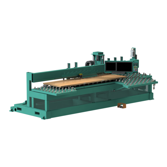
Overview of the EFX System Overview of the EFX System is a CNC door machining station designed to process all Kval EFX four door edges and door lock face holes or special shapes for card locks. The machine processes a wide range of door sizes up to 2-1/4” x 4’0” x 9’... - Page 13 Overview of the EFX System Edge detailing spindles are by Colombo and include a standard rotation 3HP, reverse rotation 3HP, 11HP deep mortise, and 2HP drill spindle for screw pilot holes. Four corner chisels are stan- dard to square hinge pockets or lock face plates. The entire edge detailing tower automatically pivots from zero to three degrees to match the door edge, including mid sequence for face plate and deep pocket lock.
-
Page 14: About This Manual
Overview of the EFX System About this Manual This manual is part of a package delivered with the machine line. Integration Package includes the following: includes the following: Operation Manual Chapter Title Description Introduction Descriptions of Machine Line and Safety Information. -
Page 15: Safety First
Training Ensure that all employees who operate this machine are aware of and adhere to all safety precautions posted on the machine and are trained to operate this machine in a safe manner. KVAL Operation Manual... - Page 16 All cylinders on machine are under high pressure and can be very dangerous when activated. Before performing any mainte- nance or repairs on this machine turn off the main air disconnect. Lockout and tagout this connection. See “Lockout Tagout Procedure” on page 1-10. KVAL Operation Manual...
- Page 17 This should be done in accordance with applicable state and/or federal code requirements. Laser Warnings On some machines, laser indicators are used to set boundaries. Follow the manufacturers safety precautions. KVAL Operation Manual...
- Page 18 Follow Your Company’s Safety Procedures In addition to these safety guidelines. Your company should have on-site and machine specific safety proce- dures to follow. KVAL Operation Manual...
-
Page 19: Lockout-Tagout Guidelines
O..OFF! Shut off all power sources and isolating devices P..Place lock and tag E..ENERGY: Release stored energy to a zero-energy state R ..Recheck controls and test to ensure they are in the “OFF” state KVAL Operation Manual... -
Page 20: Lockout Tagout Procedure
Turn Switch to the Lock and Tag out Insert Lock into hole. OFF position Note: When multiple people are working on the machine, each person needs to have a lock on the handle in the extra holes provided. KVAL Operation Manual 1-10... -
Page 21: Lockout Tagout Air Supply
The lock and tag can now be removed (only by the person(s) who placed them), and the machine can be re-energized. The tags must be destroyed and the locks and keys returned to the lockout center. KVAL Operation Manual 1-11... -
Page 22: Zero-Energy To Start-Up
Service team. See “Getting Help from KVAL KVAL” on page 1-14. Check Controls Confirm that all switches are in the “OFF” position. Please be advised that some com- ponents of the machine may start automatically when energy is restored. - Page 23 Be sure to follow the P-R-O- P-E-R lockout/tagout procedures, and that those around you do also. Close the Cage Gate Verify all cage gates are securely closed. Ensure all safety protocols are in effect. KVAL Operation Manual 1-13...
-
Page 24: Getting Help From Kval
Getting Help from KVAL Getting Help from KVAL Before you seek help, first try the troubleshooting procedures. Follow the procedures below. If you are unable to resolve the problem: Locate the machine’s Specification Plate and record the serial number, 3 phase volts, electrical print number, and air print number. -
Page 25: Kval Return And Warranty Policy
KVAL Return and Warranty Policy KVAL Return and Warranty Policy KVAL's goal is to provide customers with high quality products. If, for any reason, you are not completely satisfied with your purchase, please contact us at: Email: parts@kvalinc.com +1 (800) 553-5825 Phone: •... -
Page 26: Customer Errors
Kval provides a warranty to products that are deemed defective. Within 30 days of discovery of said defect, please notify Kval, but no more than one (1) year after delivery will the product be covered under Warranty. The repair, replacement, or payment in the manner described above shall be the exclusive remedy of Buyer for breach of Kval’s warranty or for claims based upon failure... -
Page 27: How To Download The Service Application
KVAL tab. Follow the instruc- Support tions on the Support web page. Click the Download button to download the application that allows the technician to KVAL have access to the operator sta- tion. KVAL Operation Manual 1-17... - Page 28 Sample of i.e Explorer: Located at the bottom of the screen. select the arrow and choose Save and Run A pop-up window is displayed. Accept the request to run the program. Note: Security settings may differ from plant to plant. If issues occur, con- tact your IT department. KVAL Operation Manual 1-18...
- Page 29 Session code: An internal number to track this machine. It is auto filled. Your Name Field: Enter your name. The KVAL techni- cian will use this field to identify this machine. Description: Enter machine Serial number and issue.
- Page 30 How to Download the Service Application Page Intentionally Left Blank KVAL Operation Manual 1-20...
-
Page 31: Safety Sign-Off Sheet
Note: It is recommended you make a copy of this sheet for new operators. If a copy is needed, you may download a PDF at the website (http:// KVAL www.KVALinc.com). You may also contact our Service Department at (800) 553-5825 or email at service@KVALinc.com. KVAL Operation Manual 1-21... - Page 32 Safety Sign-Off Sheet KVAL Operation Manual 1-22...
- Page 33 Screen job creation. Description of the Machine Line Screen.: Includes page 2-14 About the Machine Line Line Control Buttons, Queued Jobs and Machine Screen Activity. Instruction to back up data. page 2-18 About Backing up Data KVAL Operation Manual...
-
Page 34: Summary Of The Kvalcam Interface
Some line control is available. See “About the Machine Line Screen” on page 2-14. Machine Control For instructions to use the machine control interface, see “About the EFX Process” on page 3-2. KVAL Operation Manual... -
Page 35: About The Libraries Screen
Door Job ing of the door can be processed using this information. Detail Feature Door Job Group Saves Cut Information Saves Door Parameters Many Number of Feature Groups Allowed Load Work Onto Machines (Cut Doors) KVAL Operation Manual... -
Page 36: Library Screens
Use the buttons at the bottom of the screen to create, clone, edit, or delete jobs or Feature Groups. Lock editing capabilities and refresh tabs are also available. Note: The have the same layout and storage for- Door Job and Features Group Library mat. KVAL Operation Manual... -
Page 37: About The Feature Groups And Door Jobs
Jumps to the Job to Delete. to copy and add password to Creation Screen rename. edit the data- (The Most Common Path way base.(Customer to start the door Machining requested option) Process) KVAL Operation Manual... -
Page 38: About Job Creation
, select the item from or Template button at the bottom of the the table, then select the Edit /View screen. button on the bottom of the page. bottom of the screen. Screen Shot of Job Creation FIGURE 2- 1. KVAL Operation Manual... -
Page 39: About The Job Name Menu
FeedRate% Override: Adjust the plunge rate of the drill / routers. Adjusts to door materials. For example, for a harder material would call for a lower percentage. Note: Changes in the door parameters and door hand are reflected in the menu. Job Preview The door illustration will change in shape. KVAL Operation Manual... -
Page 40: About The Feature Tree Menu
Validation • : Select a Group or Child. Right click the mouse button. Cut/Copy and Paste Choose Cut or Copy from the list. Position mouse at the desired location in the tree. Right click and choose Paste. KVAL Operation Manual... -
Page 41: About The Selected Feature Details Menu
Door Job. Select Add Property. Add a Name and Expression. Error checking will help in adding the correct data. In the Children Feature Detail Screen, add a hashtag (#) in front of the created property name. KVAL Operation Manual... -
Page 42: About The Selected Feature Details Menu (Child Level)
• Lock Edge • Hinge Jamb • Lock Jamb Data Table: Parameters of the cut. Includes Hinge Predrill locations. Manage Augmentations: Add augmentations to the created Feature. Augmentations are created at the factory to ad to common cuts. KVAL Operation Manual 2-10... -
Page 43: About The Control Buttons
Door Job. The background program will translate the param- eters to a dxf file. To view the file use a program that opens.dxf files. (For example: Auto-Cad ® Draftsight ® ) Use this blueprint to share for review. KVAL Operation Manual 2-11... -
Page 44: About The Job Preview Screen (2D And 3D)
Top End view or and OFF Line or and OFF view. Note: May • Hinge Edge use the mouse • Lock Edge wheel to zoom in • Hinge Pivot Face and out. • Opposite Pivot Face KVAL Operation Manual 2-12... - Page 45 Select the 3 D Tab to display a three dimensional view of the Door Job. Right click the mouse to control the movement of the 3 D display. are color coded and listed on the display. Preview Surfaces KVAL Operation Manual 2-13...
-
Page 46: About The Machine Line Screen
For each machine, a table shows job name, quantity of remain- ing doors, doors being processed, and status of the machine. Queued Jobs: Shows a list of the upcoming jobs. Line Controls: Common operations to control the machine line Machine Line Screen KVAL Operation Manual 2-14... - Page 47 Door Job doors left in the Door Job: Lists the name of the Job being processed. The Job name reflects the name assigned in the Door Job Library. Machine: Lists the machines in the line. KVAL Operation Manual 2-15...
- Page 48 Creation Time: List the time when the job is put in queue. Template: List the File name of the Template. Job: List the file name of the Job. Queue Order: Lists the jobs that are going to be processed KVAL Operation Manual 2-16...
- Page 49 Screen Reset the Machine Line: Press to Home the Machine Line: Press to reset the every machine in the Home every machine in the line line. You Must Home the line after this reset is performed. KVAL Operation Manual 2-17...
-
Page 50: About Backing Up Data And Checking The Revision Status
About Backing up Data and Checking the Revision Status Right Click the KVAL Icon at the bottom of the screen to display this popup. Note: Select icon from the windows screen and drag to the favorites bar for access to this icon. -
Page 51: Definitions
Inputted values by the user for an intended feature. The input is interpreted by the program and passed through a validation scheme for all machines in a line to determine if the intended cut is capable of being run (see validation). KVAL Operation Manual 2-19... - Page 52 Libraries (e.g. material types) will produce unexpected or potentially harmful results to the machine and/or operator. Some cuts in fringe cases may pass validation that result in non-conforming cuts (cut does not match visual representation). KVAL Operation Manual 2-20...
-
Page 53: Appendix: Job Preview Examples
Width) for a quick refer- ence. Note: Errors will be indicated by an orange box around the parameter. Note: Change views by using the manual view buttons at he bottom of the screen. Lock Parameters Lock Locations KVAL Operation Manual 2-21... -
Page 54: Door Edge (Lock Preview)
Width) for a quick refer- ence. Note: Errors will be indicated by an orange box around the parameter. Note: Change views by using the manual view buttons at he bottom of the screen. S Lock Parameters and Locations KVAL Operation Manual 2-22... -
Page 55: Door Edge (Hinge Preview)
Width) for a quick refer- ence. Note: Errors will be indicated by an orange box around the parameter. Note: Change views by using the manual view buttons at he bottom of the screen. Lock Parameters and Locations KVAL Operation Manual 2-23... -
Page 56: Appendix: About Validation
An Orange Box will highlight the group with an error. In this sample, the has an error Lock Edge Child To investigate the error, select the Vali- button at the bottom of dation Report the display. KVAL Operation Manual 2-24... -
Page 57: About The Validation Screen
Lock Edge routine Either change the depth in the table of the Feature Table or select Commander 3-Tool Con- and change the fig- Lock Tools depth in the Depth Stop (Z Loca- field to match desired tion) depth. KVAL Operation Manual 2-25... -
Page 58: About The Litecutout Feature Detail (Dl-Ncd Only)
LiteCutout If needed, add a Feature Group. Add a to the Child Feature Tree Select from the drop down menu and add a LiteCutout Feature Type Feature .add a Feature Name. Name Select the Edit Button. KVAL Operation Manual 2-26... - Page 59 About the LiteCutout Feature Detail (DL-NCD Only) Add Group Add Child Select LiteCutout and Name Select the Edit Button working space is displayed. LiteCutout Select the and select the desired file from your directory. If Import DXF Button needed, manipulate the shape. KVAL Operation Manual 2-27...
- Page 60 About the LiteCutout Feature Detail (DL-NCD Only) Import DXF file In this example, an oval DXF file was imported. Add the file into by selecting the KvalCAM OK Button. Input to put the cut onto the door. WLocation LLocation KVAL Operation Manual 2-28...
- Page 61 About the LiteCutout Feature Detail (DL-NCD Only) If finished with editing the , run the door. Door Job KVAL Operation Manual 2-29...
-
Page 62: About The Litecutout Screen
About the LiteCutout Feature Detail (DL-NCD Only) About the LiteCutout Screen This section describes selections on the Screen. LiteCutout KVAL Operation Manual 2-30... -
Page 63: About The Work Area Coordinates
0,0 origin point: Referenced to the LLocation and WLo- cation on the door. X Negative: X Positive: goes toward goes toward the the Top of the Door. Bottom of the Door Y Negative: goes toward the Lock Edge. KVAL Operation Manual 2-31... -
Page 64: Sample Oval Cut
Knockout Point: Points may be added with the Insert Knock Out Point button located under LiteCutout Parameters menu. Plunge Point: Point may be adjusted with controls in the LiteCutout Parameter menu or moved manually with the mouse. KVAL Operation Manual 2-32... - Page 65 OK: Send to KvalCAM Cancel: Stop work and go back to KvalCam. Insert Vertex: Insert another Vertex point along the cutting path. Delete Selected: Delete any selected point on the shape. KVAL Operation Manual 2-33...
- Page 66 About the LiteCutout Feature Detail (DL-NCD Only) KVAL Operation Manual 2-34...
- Page 67 CHAPTER 3 Operation of the EFX Line This chapter describes components, assemblies, and the user interface of the KVAL EFX System The content is geared to help operators understand the basic operation of the machine. Included are instructions to calibrate the machine and process a door.
-
Page 68: About The Efx Process
Actions If needed, set the job parameters from the EFX Main .See “About the EFX Interface Screens” on Screen Pull door in page 3-13 for instructions. -
Page 69: How To Position A Door For Cutting
3º 3º Types of Cuts Follow the on screen instructions to position the door. Use this position for: • Hinge Cuts • Lock Cuts • Face Cuts Use this position for: • Top Cuts • Bottom Cuts KVAL Operation Manual... -
Page 70: Summary Of The Controls On The Machine Line
See “The Machine Start Summary” on page 3-8 Control Process: See “About the EFX Process” on page 3-2 Machine Control Software: See “About the EFX Interface Screens” on page 3-13 Full Definition: See “Operator’s Station on the Edge-SS” on page 5-5 Main Machine Controls Machine Start: See “The Machine Start Summary”... -
Page 71: Indicator Light
Indicator Light Descriptions TABLE 3-1. Color Description of Process Machine in Error State -Low Air Pressure Yellow -X Axis Auto Greaser Empty -(Solid) un Cutting Routine Green -(Blinking) Ready to Start -No Remaining Work on the Door Blue KVAL Operation Manual... -
Page 72: Initial Powering Operations For The Efx
Initial Powering Operations for the EFX Initial Powering Operations for the EFX This section describes how to power up and to power down the Powering up the system includes: • Applying power to the entire system • Starting the Control Circuit Powering down the system includes: •... -
Page 73: How To Power Down The Machine
For each machine, switch the green Control switches to the position. Circuit Kval also recommends that you turn the dis- connect switches on the electrical cabinets to OFF; this helps reduce possible damage due to power surges from electrical storms. Step 3... -
Page 74: The Machine Start Summary
Job has been created to be used in the machining process. To learn more about Door Jobs and Templates, see “About the EFX Interface Screens” on page 3-13. Ensure factory air and power is present at the machine. For more information: “Initial Powering Operations for the EFX”... - Page 75 (after secur- 3. DOOR CLAMP Position Door ing the door) button 4. START SEQUENCE If completed for the day, power down the machine. For more information: See “How to Power Down the Machine” on page 3-7 KVAL Operation Manual...
-
Page 76: Summary Of The Kvalcam Interface
Machine Control and Calibration Screens Main Control Includes auto controls, speed control, and sequence controls See “About the EFX Main Screen” on page 3-13. Manual Servo Control From this screen, move the Cutting Head and Table. See “About the Edge SS Manual Servo Control Tab” on page 3-17. -
Page 77: Status And Log Screens
See “About the Status and Log Screens” on page 3-25. Log Screen From this screen, the feedback codes from the machine. See “About the Status and Log Screens” on page 3-25. KVAL Operation Manual 3-11... -
Page 78: About Machine Status Feedback
Select the tabs to jump to associated Operator’s Screen. active screen will highlight with a green background KVAL Operation Manual 3-12... -
Page 79: About The Efx Interface Screens
About the EFX Interface Screens About the EFX Interface Screens Operator Screens contains the controls to operate the machine. Select the located on the left hand side of the machine to jump to EFX Tab this menu. Tabs Description Main Control This screen includes access to the most commonly used controls for the Machine. -
Page 80: Efx Main Screen
About the EFX Interface Screens EFX Main Screen About the EFX Main Control Section Home Machine This button starts the home sequence on the machine, which scans to find a physical reference point on the frame. When this point is found, the position is stored and... - Page 81 About the EFX Interface Screens About the Sequence Control Section Start Sequence • After templates and programs are loaded, the doors are in place to process, the machines is homed, Press the Start Sequence button to run the machine line.
- Page 82 About the EFX Interface Screens About Other Controls Toggle Clamp Press to toggle the door clamps UP or DOWN. This button is only available when a job is loaded in the machine. Toggle Door Stop Press to toggle the door stops UP or DOWN. This button is only available when a job is loaded in the machine.
-
Page 83: About The Edge Ss Manual Servo Control Tab
Face servo motors can be moved manually. EFX Manual Control Screen FIGURE 3- 2. About the EFX Face Servo Controls The manual controls are designated by Y and Z axises for the Press and Face Tool Set. hold the button ( ) to move the tool set in the desired direction. - Page 84 About the Edge SS Manual Servo Control Tab About the EFX Main Servo Controls The manual controls are designated by X, Y, and Z axises for the . Press and Main Head hold the button ( ) to move the head in the desired direction.
-
Page 85: About The Tool Path Preview Test Tab
Step 3 Center Circle represents the Point tool and the animation represents the path Select a G-Code routine form the drop down menu. Select the Render Button View the path of the tool on the screen. KVAL Operation Manual 3-19... -
Page 86: About The Tool Config Tabs
• Parameters of the cut (depth, passes through material, overlaps, skin priority) • Chisels: Can change peck count (start of cut), corner location, and rate of machin- ing. Select Tab Unlock, Lock, and Save Data List of Tools Available Pop-Up Menus: enter tool data.(Routers,Drills,and Chisels) KVAL Operation Manual 3-20... -
Page 87: Unlock The Tool Slot Configuration
Below are samples of the pop-up windows Enable Check Box available About the Tool Pop-up Screens Drill Pop-up Drill Pop-up Disabled Sample Drill Configuration Pop-Ups Drill Pop-up Sample Drill Pop-up Disabled Sample KVAL Operation Manual 3-21... -
Page 88: Sample Chisel Configuration Pop-Ups
Note: Below are factory suggested locations. Identification of the slots can be altered through this menu. Face Router 2 Face Drill 1 Face Router 1 Point to Point Main Plate Router Counter Rotate Router Deep Mortise KVAL Operation Manual 3-22... -
Page 89: About Chisel Locations
Identify the tool that needs replacement.Measure tool dimensions and capture the data. (Use this information to populate the pop-up screens). Drill or Router Select the from the desired assembly Tool Slot Enter the data into the pop-up screen. (Router or Drill) KVAL Operation Manual 3-23... -
Page 90: Measuring Tool Length
Insert specifications of the tools being used to make the cuts. Ability to name the tools to user defined descriptions. Customize the tools to reflect the actual tool parameters, making the most accurate cuts. Ability to define cut operation. KVAL Operation Manual 3-24... -
Page 91: About The Status And Log Screens
(idle, operation). The data can be filtered to observe certain aspects of the operation of the machine. This tool is great for troubleshooting to locate faulty assemblies. Filter Data List of Parameter of Door in Process Status is listed by Location Status Screen FIGURE 3- 3. KVAL Operation Manual 3-25... -
Page 92: About The Log Screen
The Log screen displays all the tasks the performs. This screen can help with trouble KVAL EFX shooting by associating the error code to machine sections or functions. The top line will have the most current routine that is running. The codes are color coded:... -
Page 93: Description Of The Light Tower
Solid: General Error • Flashing: Not Ready to Re-Start (E-Sop Switch is Active) Green: Machine is Operational Off: No Control Power Control Power ON (Green): 24 VDC Control Power ON Ready to Work Light Tower Rev 2 KVAL Operation Manual 3-27... -
Page 94: Appendix: About Backing Up The Data
Note: recommends backing up locally and to a isolated server. Build Info Click to view upper level notes about the cur- rent build. Release Notes: Click to open a PDF of the history of release notes on this version o software. KVAL Operation Manual 3-28... - Page 95 Appendix: About Backing up the Data KVAL Operation Manual 3-29...
- Page 96 About the Calibration Tabs page 4-3 Descriptions of the Calibration Tabs. How to Enter Calibration Data page 4-7 Descriptions of how to use the calibration screens About the Calibration Screen page 4-9 Descriptions of the calibration available. KVAL Operation Manual...
-
Page 97: About Calibration
Calibration is all about the confidence in the end results of your manufacturing process. Calibra- tion assures you that your cut parameters are accurate and within the specified limits. If slight discrepancies in the machining of a door are observed, the built in KVAL calibration can adjust the tooling to fix the issue. -
Page 98: About The Calibration Tabs
Log Screens reporting. Finding errors from these screens will help localize problem areas. Note: If the machine issues can not be resolved, call KVAL Inc. (1-800-553-5825). Have any error code that is displayed, ready to give the KVAL representative. This will aid in troubleshooting and shorten down time. -
Page 99: Unlock The Calibration (Option)
Access to the calibration is password protected. (Optional) Select the button Unlock At the pop-up, enter Password the password and select OK to continue. The calibration message will change from a red ''Calibration is Locked '' to a green Calibration is Unlocked”. KVAL Operation Manual... -
Page 100: Enter A Positive Or Negative Number
Y-Axis positive the direction of the X-Axis X-Axis Positive movement Door Edge Axis Directions Stand at the Lock Side of Door, point at the edge of the door with the left hand rule to determine axis direction KVAL Operation Manual... -
Page 101: Door Face Axis Directions
Enter a Positive or Negative Number? Door Face Axis Directions Stand at the Lock Side of Door, point down at the face of the door with the left hand rule to determine axis direction KVAL Operation Manual... -
Page 102: How To Enter Calibration Data
Note: Maximum offset is 0.50 inches. If more than 0.50 inches of adjustment is needed, there is a high probability that another issue may be causing a problem. If issues can not be resolved, contact the KVAL Service Center KVAL Inc. (1- 800-553-5825). -
Page 103: About Restore Points
Name and enter to save To Load or Delete a Restore Point: Select the restore point from the menu Select the button to use the calibration. Select the button to load Load Load Select the button to delete the point. Delete KVAL Operation Manual... -
Page 104: About The Efx Calibration Screen
About the EFX Calibration Screen About the EFX Calibration Screen contains a list of calibration adjustments. Select the located on the Calibration Screen EFX Tab left hand side of the machine, then select the to jump to this menu. Enter adjust-... -
Page 105: About Calibration Sequence
• See “Step 4: Calibrate the Face Axes” on page 4-16 • See “Step 5: Calibrate the Face Tools” on page 4-18 • See “Step 6: Calibrate the Edge Carriage” on page 4-20 • See “Step 7: Calibrate the Edge Tools” on page 4-21 KVAL Operation Manual 4-10... -
Page 106: Step 1: Calibrate The Carriage Stop
Operator’s Station Carriage Stop below If not in specification, adjust the location. Repeat until specification is reached. For polarity of value to enter, see “Door Edge Axis Directions” on page 4-5. 20.0 '' Stop Calibration FIGURE 4-6. KVAL Operation Manual 4-11... -
Page 107: Step 2: Calibrate The Length And Thickness Feelers
Measure the Length of the door and capture it. Measure the Thickness Create a input the actual measurements of the door. Door Job, Add Actual Measurements of the Door KVAL Operation Manual 4-12... - Page 108 Compare the actual measured data with the calculated data. If the measurement feedback is that the actual measurement, thickness less input a positive value If the measurement feedback is that the actual measurement, length less input neg- ative value KVAL Operation Manual 4-13...
-
Page 109: Step 3: Calibrate The Depth Feeler (Option)
Run a Door Job. Check the Depth Probe Pad position as it touches the door edge. Pad on probe should cover at least 50% of the door edge. Probe Pad Probe Pad Pad covers door edge at least 50% coverage Door Edge KVAL Operation Manual 4-14... -
Page 110: Process To Calibrate The Probe Depth
If a value is displayed, enter a value to zero the probe reading. negative negative Run the door and verify the displayed feed back is zero. KVAL Operation Manual 4-15... -
Page 111: Step 4: Calibrate The Face Axes
Configuration Menu Z-Axis. Face Axis Calibration Reference Cut The figure below, shows a sample reference cut and the type of offset to input into the calibration menu. See “How to Enter Calibration Data” on page 4-7 KVAL Operation Manual 4-16... - Page 112 Step 4: Calibrate the Face Axes KVAL Operation Manual 4-17...
-
Page 113: Step 5: Calibrate The Face Tools
( ). This is a global calibration. Therefore, by calibrating, other Z-Axis tools may be out of calibration. For directions on how to use the configuration menus, See “About Using Tool Configuration” on page 3-23 KVAL Operation Manual 4-18... -
Page 114: Face Tools Calibration Reference Cut
Z-Axis Face Tools Calibration Reference Cut The figure below, shows a sample reference cut and the type of offset to input into the calibration menu. See “How to Enter Calibration Data” on page 4-7 KVAL Operation Manual 4-19... -
Page 115: Step 6: Calibrate The Edge Carriage
Configuration Menu Z-Axis. Edge Axis Calibration Reference Cut The figure below, shows a sample reference cut and the type of offset to input into the calibration menu.See “How to Enter Calibration Data” on page 4-7 KVAL Operation Manual 4-20... -
Page 116: Step 7: Calibrate The Edge Tools
Routs the edge pocket Counter Rotate Hinge Router: Routs the hinge pocket providing a Face Cutter clean cut. Deep Mortise Router: Routs a deep pocket. Zero/Three Degree Cylinder Tog- gles the Head for 3 and 0 degree cuts KVAL Operation Manual 4-21... -
Page 117: Chisel Locations
Y-Axis • If the cut is out of specification, the needs to be adjusted.If the depth Z-Axis cor- of the lock cut are out of specification, the needs to be ners Chisels Offsets adjusted. KVAL Operation Manual 4-22... -
Page 118: Edge Tools Calibration Reference Cut
See “Routers: How to Isolate and Calibrate a Specific Router” on page 4-24 Chisels Check location and shape of each corner cut. If needed, input the offset polarity as seen in the figure above. KVAL Operation Manual 4-23... -
Page 119: Routers: How To Isolate And Calibrate A Specific Router
In the process the depth of the rectangle may be measured to calibrate the Z of the tool. Once the tool calibration are verified, the , and may be calibrated Diameter by measuring from the edges of the rectangle to the edges of the door. KVAL Operation Manual 4-24... - Page 120 Routers: How to Isolate and Calibrate a Specific Router Appendix: Servo Motor Drive Assemblies Face Cutter Z Axis Face Cutter Y Axis Edge Cutter Y Axis Edge Cutter Z Axis Edge/Face Cutter X Axis KVAL Operation Manual 4-25...
- Page 121 Routers: How to Isolate and Calibrate a Specific Router KVAL Operation Manual 4-26...
- Page 122 CHAPTER 5 Tour of the EFX Line This chapter describes components, assemblies, and the user interface of the KVAL EFX System. The content is geared to help operators understand the basic operation of the machine. Chapter 5 at a Glance...
-
Page 123: Front View Of The Efx
Contains mechanical Machine Controls. See “EFX Fence and See “Operator’s Station on the EFX” on Door Clamps” on page 5-3 page 5-5 Note: Multiple machine controls may com- bined in one station (Machine Combina-... -
Page 124: Operator's Station On The Efx
“Summary of the KvalCAM Interface” on page 2-2. KvalCam, For information about the machine control interface , see “About the EFX Process” on page 3-2. Touch Screen Interface: Main Control of entire machine line. Download KvalCAM Templates to set the specifications of door machining. -
Page 125: Efx Controls
EFX Controls EFX Controls This section describes the controls on the Main Machine Controls Door Position Lights: Indicates the selected door edge. Control Circuit: Activates the power from the Electrical Panels. Machine Power: Applies power to the machine. Emergency Stop: Push to shut the machine down in emergency situations. -
Page 126: Efx Fence And Door Clamps
EFX Controls EFX Fence and Door Clamps The door is loaded into the machine and set on the stationary fence. Press the door against the and the . After the door is set, clamp the door. Door Stop Fence Pop Down Fence: Fence extends down to set a reference for the door. -
Page 127: Assemblies On The Main Cutter Head
3 degree / 0 the face of the door degree Axel Standard Router: Routs the door facet Y-Axis Servo Motor (Face) Edge Tools Valve Bank Electronic Node: Connections from the Face Tools Valve Bank X-Axis Servo Motor Electrical Panel KVAL Operation Manual... -
Page 128: About Door Probes
Probe in action. the ‘L” shaped probe measures thickness at the face of the door while the Probe Assembly length is measured at the edge Encoder of the door. KVAL Operation Manual... -
Page 129: Depth Probe
After the door has been fed in to the door stop and clamped, the probe lightly taps the face of the door. The feeler and encoder work with the drill location to provide an accurate depth. Probe in action.The probe actively measures the edge of the door during routing to achieve the accurate depth. Depth Probe Assembly KVAL Operation Manual... -
Page 130: Laser Safety Scanners
There are two classifications of sensors on the Face-SS: Photo Electronic and Inductive Proximity Sensor. Proximity Sensors Used on Cylinders Photo Eye Detector Proximity Detector Emitter and Receiver in Senses metallic objects one package Examples of Sensor FIGURE 5-3. KVAL Operation Manual... -
Page 131: Location Of Servo Motors And Valve Bank Locations
Note: Labels on the solenoids identify loads they control. Table Valve Bank 2 Table Valve Bank 1 Face Cutter Head Tools Air Input Edge Cutter Head Valve Stop Valve Bank Location of Valve Banks FIGURE 5-4. KVAL Operation Manual 5-10... -
Page 132: About The Electrical Panels
Main Electrical Panel, High Frequency Panel the Frame. This section is an overview of the electrical components. Refer the machine's electrical prints for in-depth information EFX Main E-Panel The Main Electrical Panel: • Supplies voltages to the machine • Contains the Programmable Logic Controller •... -
Page 133: Efx High Freq Panel
About the Electrical Panels EFX High Freq Panel The High Frequency Panel • Supplies voltages to the machine • Contains the interface serially connect Main PLC • VFDs (Variable Frequency Drives) to interact with the cutter motors PLC (EFX) 24 VDC and 110 VAC Terminals... -
Page 134: About The Nodes
Inputs and Outputs Top Ethernet cable is PLC Bottom Ethernet goes to Cutter Node Interconnect Bar Sample of a Frame Node FIGURE 5-7. Typical Block Diagram of Network Connections Block Diagram of Network Connections FIGURE 5-8. KVAL Operation Manual 5-13... -
Page 135: Graphical Sample Of Node Connections And Power Distribution
Points in the machine Power Main E Box: Contains Servo Drives Network Connec- Cutter Node tions, power, and Inputs/Outputs originate this box and are connected to Nodes. Frame Node Location of Nodes on the EFX FIGURE 5-9. KVAL Operation Manual 5-14... - Page 137 Toggle Clamp 16 Toggle Stop 16 inductive proximity sensor 9 zero-energy start-up clean up 12 lockout and tagout Guidelines 12 inspect 12 lockout procedure 10 log screen description 26 main electrical panel description 11 manual operation interface 17, 19 Kval EFX...
- Page 138 Index Kval EFX...
- Page 140 Contacting KVAL Customer Service Phone and Fax: Mailing address: In the U.S and Canada, call (800) 553-5825 or fax Customer Support Department (707) 762-0485 Kval Incorporated Outside the U.S. and Canada, call (707) 762-7367 825 Petaluma Boulevard South or fax (707) 762-0485 Petaluma, CA 94952 Email: service@kvalinc.com...
Need help?
Do you have a question about the EFX and is the answer not in the manual?
Questions and answers