
Subscribe to Our Youtube Channel
Related Manuals for Kval EFX


Summary of Contents for Kval EFX
- Page 1 Service Manual Published: March 2, 2020 Innovation, Quality & Honesty EFX Door Machining System...
- Page 2 Proprietary Notice This Manual is confidential and contains proprietary information and intellectual property of KVAL Inc., and is to be used solely by Customer as an operating manual for KVAL Inc. machines. Neither this Manual nor any of the information contained herein may be reproduced or disclosed under any circumstances without the express written permission of KVAL Inc.
- Page 3 KVAL EFX System Service Manual Your Feedback is Welcome: To help us design products that make your job easier and your business more successful, we'd like to gain your perspective about your user experience with our product - that is, the manual, the machinery, the software, etc.
- Page 4 KVAL EFX System Service Manual...
- Page 5 LICENSE. IF YOU DO NOT AGREE TO ALL OF THE TERMS OF THIS LICENSE, THEN DO NOT USE THE KVALCAM SOFTWARE. KVAL, Inc., is the owner of all rights in respect of the software and documentation (referred to as “Licensor”). You are the purchaser of KVAL Machinery operated by the KVALCAM Software are the “Licensee”.
- Page 6 KVAL EFX System Service Manual...
-
Page 7: Table Of Contents
Table of Contents Introduction to the Edge-SS System Chapter 1 Overview of the EFX System........... 1-2 About this Manual ..............1-3 Safety First!................1-4 Safety Sheet Sign-Off Sheet..............1-4 Safety Terminology of Labels..............1-4 Safety Guidelines..................1-4 Lockout-Tagout Guidelines ............1-8 Follow the P-R-O-P-E-R lockout rule of thumb........1-8 Lockout Tagout Procedure............ - Page 8 Tapered Bearing Housings ..............3-17 Ball Screw Nut ..................3-18 Ball Screw Drive Assembly..............3-18 Pulley and Idler Shafts (If Applicable)..........3-19 Sample of Grease Locations for EFX ........3-20 Locations of Hub Bearings..............3-20 Locations of Rail Bearings on the Carriage Head.......3-21 Edge Cutting Section Lubrication ............3-22 Face Cutting Section Lubrication............3-23...
- Page 9 Stops and Probe Assembly Lubrication ..........3-24 Description of Air Input System ..........3-27 Air Input with Lubrication ..............3-27 Air Line Without Lubricator ..............3-28 Identifying EFX Tools ............... 3-29 Tool Information for the Edge Cutter...........3-29 Tool Information for the Face Cutter ...........3-30 About Chisels................3-31 Chisel Orientation on Machine............3-31...
- Page 10 Table of Contents Adjusting Cylinder Retraction Speed ..........4-17 Valve Bank Locations .............. 4-18 Location of Valve Banks on the EFX ..........4-18 Network System Overview............4-19 Connections to Servo Drives ..............4-19 EFX Servo Motor Locations..............4-20 About Switches and Sensors........... 4-21 Using Sensors to Trouble Shoot ............4-22 About Checking the Revision Status........
- Page 11 Notes:...
- Page 12 TABLE 1- 1. Section Name Summary Page This section provides an overview of the page 1-2 Overview of the EFX Door machine. It includes a general description System and a table of available options IMPORTANT safety information is page 1-5...
-
Page 13: Overview Of The Efx System
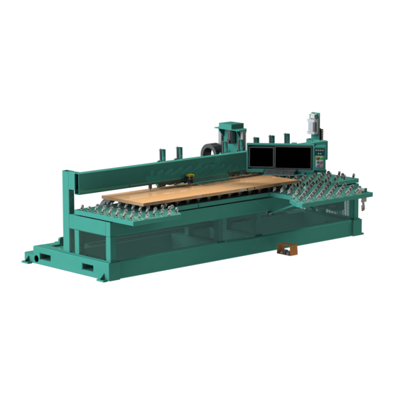
Overview of the EFX System Overview of the EFX System is a CNC door machining station designed to process all Kval EFX four door edges and door lock face holes or special shapes for card locks. The machine processes a wide range of door sizes up to 2-1/4” x 4’0” x 9’... - Page 14 Overview of the EFX System pivots from zero to three degrees to match the door edge, including mid sequence for face plate and deep pocket lock. Three additional spindles are mounted underneath the castor table; two spindles are utilized for face routing to best suit individual cus- tomer needs (i.e bit type), the third 2HP spindle drill for lever...
-
Page 15: About This Manual
Overview of the EFX System About this Manual This manual is part of a package delivered with the machine line. Integration Package includes the following: includes the following: Operation Manual Chapter Title Description Introduction Descriptions of Machine Line and Safety Information. -
Page 16: Safety First
Training Ensure that all employees who operate this machine are aware of and adhere to all safety precautions posted on the machine and are trained to operate this machine in a safe manner. KVAL Service Manual... - Page 17 All cylinders on machine are under high pressure and can be very dangerous when activated. Before performing any mainte- nance or repairs on this machine turn off the main air disconnect. Lockout and tagout this connection. See “Lockout Tagout Procedure” on page 1-10. KVAL Service Manual...
- Page 18 This should be done in accordance with applicable state and/or federal code requirements. Laser Warnings On some machines, laser indicators are used to set boundaries. Follow the manufacturers safety precautions. KVAL Service Manual...
- Page 19 Follow Your Company’s Safety Procedures In addition to these safety guidelines. Your company should have on-site and machine specific safety proce- dures to follow. KVAL Service Manual...
-
Page 20: Lockout-Tagout Guidelines
O..OFF! Shut off all power sources and isolating devices P..Place lock and tag E..ENERGY: Release stored energy to a zero-energy state R ..Recheck controls and test to ensure they are in the “OFF” state KVAL Service Manual... -
Page 21: Lockout Tagout Procedure
Turn Switch to the Lock and Tag out Insert Lock into hole. OFF position Note: When multiple people are working on the machine, each person needs to have a lock on the handle in the extra holes provided. KVAL Service Manual 1-10... -
Page 22: Lockout Tagout Air Supply
The lock and tag can now be removed (only by the person(s) who placed them), and the machine can be re-energized. The tags must be destroyed and the locks and keys returned to the lockout center. KVAL Service Manual 1-11... -
Page 23: Zero-Energy To Start-Up
Service team. See “Getting Help from KVAL KVAL” on page 1-14. Check Controls Confirm that all switches are in the “OFF” position. Please be advised that some com- ponents of the machine may start automatically when energy is restored. - Page 24 Be sure to follow the P-R-O- P-E-R lockout/tagout procedures, and that those around you do also. Close the Cage Gate Verify all cage gates are securely closed. Ensure all safety protocols are in effect. KVAL Service Manual 1-13...
-
Page 25: Getting Help From Kval
Getting Help from KVAL Getting Help from KVAL Before you seek help, first try the troubleshooting procedures. Follow the procedures below. If you are unable to resolve the problem: Locate the machine’s Specification Plate and record the serial number, 3 phase volts, electrical print number, and air print number. -
Page 26: On-Line Help
Getting Help from KVAL On-Line Help ® On machines with a Beckhoff PLC and an internet connection, our service team are able to con- nect, run, and troubleshoot your machine. Product Return Procedure If you’ve contacted for help and it is determined that a return is necessary, use the procedure KVAL below to return the machine or part. -
Page 27: How To Download The Service Application
Explorer and Google web browsers. Sample of Google Browser: Located at the bot- tom left of the screen. Sample of i.e Explorer: Located at the bottom of the screen. select the arrow and choose Save and Run KVAL Service Manual 1-16... - Page 28 Session code: An internal number to track this machine. It is auto filled. Your Name Field: Enter your name. The KVAL techni- cian will use this field to identify this machine. Description: Enter machine Serial number and issue.
- Page 29 How to Download the Service Application Page Intentionally Left Blank KVAL Service Manual 1-18...
-
Page 30: Safety Sign-Off Sheet
Note: It is recommended you make a copy of this sheet for new operators. If a copy is needed, you may download a PDF at the website (http:// KVAL www.KVALinc.com). You may also contact our Service Department at (800) 553-5825 or email at service@KVALinc.com. KVAL Service Manual 1-19... - Page 31 Safety Sign-Off Sheet KVAL Service Manual 1-20...
- Page 32 The controllers are on board computers that sup- KVAL EFX ply the user interface and control the operation of the machine. Note: With the controller, KVAL can remotely help troubleshoot your machine. Chapter 2 at a Glance Section Name...
-
Page 33: About The Efx Line Computer
System IT Administration System IT Administration For optimum support, the machines require internet access. With internet access, KVAL Service Support will be able to access your machine through your company’s Intranet and help solve any issues that may occur. Connection to the Intranet is achieved by interfacing with the machine’s controller. -
Page 34: About Backing Up The Data
About Backing up the Data About Backing up the Data Right Click the KVAL Icon at the bottom of the screen to display this menu. Exit: Click to close the running Kval Cam program. to save all data from Backup Logs: Click to save the the machine operation. - Page 35 About Backing up the Data KVAL Service Manual...
- Page 36 This chapter describes preventative maintenance steps for The content is geared to KVAL EFX. guide technicians to keep a regular maintenance schedule for your KVAL machine. Keeping your KVAL machine maintained is an important piece for successful operation of your door production process.
-
Page 37: Maintenance Schedule
Maintenance Schedule Maintenance Schedule KVAL recommends the following maintenance schedule to ensure that the machine operates properly. Cycles refers to the quantity of processed doors. Cleaning curtails build up of sawdust and grime which causes issues with the operation of the machine. Inspecting, finds issues before they become problems. - Page 38 Inspect Inspect all airlines for kinks or rubbing. Lubricate Refill all lubricators. Replace fluid if milky or discolored. Use ab ISO 32 standard hydraulic oil (KVAL PN:SYS-LUBEG). Lubricate Grease Ball Nut screw bearings (if applicable). Clean Clean all bearing shafts with clean, dry cloth.
-
Page 39: 300 Cycle Maintenance Steps
Use pressured air to blow off dust and debris on entire machine. Use a clean rag to clean areas not affected by pressurized air. Also blow out any dust collection units. Check vertical bearings for loose screws. Loose screws could cause bearing damage. High Dust Accumulation Areas KVAL Service Manual... -
Page 40: 600 Cycle Maintenance Steps
Slide locking switch down to unlock twist trap to remove. Reverse action when installing trap. Inspect Tooling Inspect the Tooling for wear, (Drill Bits, Cutting Tools) See “How to Access to Bit Assemblies” on page 3-33 . KVAL Service Manual... -
Page 41: Clean Air Condition Filters
Check and empty any dust collection units. Clean any dust filters. Dust collection systems vary from machine to machine. Follow manufacturers directions to empty dust collection units. Filters Dust Collection Con- tainers Typical Dust Collection Unit FIGURE 3- 2. KVAL Service Manual... -
Page 42: 3,000 Cycle Maintenance Steps
(clicking sound) when moved to the extreme. Note: Depending on the model of limit switch, the amount of "pre-travel" (amount of movement from the arms resting position) is either 5 or 20 degrees before the limit switch actuates. KVAL Service Manual... -
Page 43: Inspect Airlines
Refill Lubricators Ensure Air is turned off. Refill all lubricators. Replace fluid if milky or discolored. Use ab ISO 32 stan- dard hydraulic oil (KVAL PN: SYS- LUBEG). Slide locking switch down twist bowl and remove. Refill bowl. Reverse action when installing trap. -
Page 44: Grease Ball Screw Bearings
Grease ball screw bearings (if applicable). For a table of lubrication types to use, Lubrication Schedule. For locations to lubricate, See Grease Ball Screw Bearings Clean Bearing Shafts Clean all bearing shafts with clean, dry cloth. Spray shaft with silicone oil and clean build up grime and dirt. KVAL Service Manual... -
Page 45: 12,000 Cycle Maintenance Steps
Cylinders not holding their position. Inspect Hydraulic Lines (If Applicable) Inspect hydraulic lines for loose fittings, leaks and cracks. Inspect hydraulic lines from the source to the end assembly. KVAL Service Manual 3-10... -
Page 46: Inspect Ball Rail Shafts
Inspect Ball Rail Shafts Inspect ball rail shafts for pitting or abrasions. Example of a Pitted Ball Rail Clean and Lubricate Slides, Cylinder Rods and Bearing Shafts Clean and lubricate all slides and cylinder rods with dry silicone spray. KVAL Service Manual 3-11... -
Page 47: 72,000 Cycle Maintenance Steps
Wash filter and lubricator bowls with soapy water. • Slide lock down to unlock. • Twist bowl to remove it. • Remove filter from Air filter assembly. Inspect and clean or replace if necessary. • Clean bowls and reas- semble. KVAL Service Manual 3-12... -
Page 48: Maintenance No-Goes
• Do not adjust any and all flow controls from factory settings • Do not remove shim stock • Do not Change or Alter any safety assemblies (E-Stops, Gate Locks, etc) • Do not Change programs in PLC’s or PC’s • Do not Alter Electrical Components KVAL Service Manual 3-13... -
Page 49: Lubrication Schedule
Lubrication Schedule Lubrication Schedule KVAL recommends the following lubrication schedule to ensure that the machine operates prop- erly. Recommended Lubrication Schedule TABLE 3-1. Type of Recommended Schedule Recommended Assembly Lubrication Type Linear Bearing Pillow Block Bearing Every 250 Hours of Machine Operation... -
Page 50: Lubrication Requirements
Closed Pillow Block Hub Style Opened Pillow Block parallel perpendicular mount Greasing Approximatively 1 Gram (one pump from grease gun) of Dura-Lith Grease (KVAL P/N: Lube EP-2). Every 250 hours of operation. Pillow Block Bearings FIGURE 3- 3. KVAL Service Manual 3-15... -
Page 51: Flange Bearing Housings
X,Y, or Z direction. Greasing Ball Rail Bearing Approximatively 1 Gram (one pump from grease gun) of Dura-Lith Grease (KVAL P/ Every 250 hours N: Lube EP-2). of operation. Ball Rail Bearings FIGURE 3- 5. KVAL Service Manual 3-16... -
Page 52: About Taper Bearings
The taper bearings differ from other machine bearing assemblies, in that they are in a sealed envi- ronment. To identify a , look at the enclosure and verify there are seals Tapered Bearing Housing between the screw and the housing. Tapered Bearing Housing Tapered Bearing Seals Tapered Bearing Housing FIGURE 3- 7. KVAL Service Manual 3-17... -
Page 53: Ball Screw Nut
The ball screw drive and the ball screw nut create very low friction coefficients resulting in a smooth, accurate, efficient movement. Greasing Approximatively 1 Gram (one pump from grease gun) of Dura-Lith Grease (KVAL P/N: Lube Every 80 hours of operation. EP-2). Ball Screw Nut Ball Screw... -
Page 54: Pulley And Idler Shafts (If Applicable)
Breakout of Pulley Assembly Pulley in Action Grease IN Note: It is important not to overfill the Idler Shaft. Avoid get- ting excess grease on the belts Grease Out Idler Shaft KVAL Service Manual 3-19... -
Page 55: Sample Of Grease Locations For Efx
Sample of Grease Locations for EFX Sample of Grease Locations for EFX This machine is a powerful electro-mechanical Caution motion control system. If servicing this machine, fol- low the safety guidelines. Failure to do so can result in damage to equipment and/or serious injury to person- nel. -
Page 56: Locations Of Rail Bearings On The Carriage Head
Sample of Grease Locations for EFX Locations of Rail Bearings on the Carriage Head To simplify the lubrication process, divide the into 3 sections. Carriage Head Edge Cut Section Face Cut Section Stop and Probe Assembly Carriage X Axis: 6 Bearings... -
Page 57: Edge Cutting Section Lubrication
Sample of Grease Locations for EFX Edge Cutting Section Lubrication Make sure that Lockout/Tagout has been performed before maintenance. For lubrication sched- ule information, see “Lubrication Schedule” on page 3-14. Rail bearings in the Edge Cutting section are highlighted in the Figure below. -
Page 58: Face Cutting Section Lubrication
Sample of Grease Locations for EFX Face Cutting Section Lubrication Make sure that Lockout/Tagout has been performed before maintenance. For lubrication sched- ule information, see “Lubrication Schedule” on page 3-14. Rail bearings in the Face Cutting section are highlighted in the Figure below. -
Page 59: Stops And Probe Assembly Lubrication
Sample of Grease Locations for EFX Stops and Probe Assembly Lubrication Identify zerk fittings and apply EP-2 grease. Use an extender to reach tight areas. Make sure that Lockout/Tagout has been performed before maintenance. For lubrication schedule information, see “Lubrication Schedule” on page 3-14. - Page 60 Sample of Grease Locations for EFX Pop Down Fence Assembly Lubrication Identify zerk fittings and apply EP-2 grease. Use an extender to reach tight areas. Make sure that Lockout/Tagout has been performed before maintenance. Each pop down gate has two bearings associated with the assembly.
- Page 61 Sample of Grease Locations for EFX Servo Motor Drive Assembly Locations (EFX) Identify zerk fittings and apply EP-2 grease. Find the X, Y and Z axis rails to identify bearings. Some bearings may be difficult to get access to. Use an extender to reach tight areas. Make sure...
-
Page 62: Description Of Air Input System
Description of Air Input System Description of Air Input System There are two types of air inputs on KVAL machinery. Not all machines have lubricator option installed. Check your machine or Air prints to verify installation. Air Input with Lubrication The air input system takes in shop air and supplies clean dry air (CDA) and lubricated air to the machine. -
Page 63: Air Line Without Lubricator
Usually 1 drop of oil every other cycle is a good rule of thumb. The approved list of oil for lubricators is as follows: • KVAL P/N SYSLUBG • Chevron AW Hydraulic Oil 32 • G-C lubricants light AW R&O •... -
Page 64: Identifying Efx Tools
Identifying EFX Tools Identifying EFX Tools This section describes the tool and motor information needed to replace tools. For torque values, see “Collet Torque Values” on page 3-39. Tool Information for the Edge Cutter Tool Information Edge Cutter FIGURE 3- 17. -
Page 65: Tool Information For The Face Cutter
Identifying EFX Tools Tool Information for the Face Cutter Front Motor # Most Collet Motor P/N KVAL KVAL Shaft Common Tool Collet Wrench PN Wrench PN 1 (Router) RS8855 COLER25-08 COLS73E478-3D (3 HP) ER25-CW WRENCH24M COLER20-02.5 2 (Drill) JLD1563 COLSE55E389 (1.5 HP) -
Page 66: About Chisels
Some machines have a rectangle orientation or a vertical orientation. Below are samples of each Rectangle Orientation Sample is taken from a Face- SS Vertical Orientation Sample is taken from an Edge- SS Upper Right Chisel Upper Left Chisel Lower Right Chisel Lower Left Chisel KVAL Service Manual 3-31... -
Page 67: Changing Chisels On A Machine
Verify that the chisel does not wobble in the fixture after tightening. Chisels should be rigid and straight in the assembly. Push the chisel cylinder back into the machine head. Clear the machine area and turn back on air and power to the machine. KVAL Service Manual 3-32... -
Page 68: How To Access To Bit Assemblies
Shutdown the machine and follow the “Lock Out Tag Out procedures. About the Tool Kit A Tool Kit is provide with each machine. Kval recommends to torque the collet to the recom- mended values. See “Collet Torque Values” on page 3-39... -
Page 69: Remove And Replace The Router Or Pre-Drill Bits
Remove Old Bit Use a collet wrench to remove the bit on the pre-drill or router assemblies.See Fig- ure below. Collet Wrench Shaft Wrench Removing Pre-Drill or Router Bit. FIGURE 3- 18. KVAL Service Manual 3-34... - Page 70 Verify that the chisel does not wobble in the fixture after tightening. Chisels should be rigid and straight in the assembly. Push the chisel cylinder back into the machine head. Clear the machine area and turn back on air and power to the machine. KVAL Service Manual 3-35...
-
Page 71: Replacing The Self Lubricator
The alert is a 30 day warning, but it is recommended to change it as soon as possible. Refer to Electrical Drawing for connections labels. Electrical Connector Lubricator Well Sensor Hose Connection Female Location of Gear and Lubricator FIGURE 3- 20. KVAL Service Manual 3-36... - Page 72 • Set the number 7 switch to the “ON” position. This turns the Lubricator “ON” • Ensure the remaining switches are set to “OFF” Disconnect the black and red wires from the machine connector with a small screw- driver. KVAL Service Manual 3-37...
- Page 73 Verify the oil is being applied to the gear and there is no alert on the user screen. The lubricator well will have blinking light when in operation. Reattach grate and secure wires with a zip tie. KVAL Service Manual 3-38...
-
Page 74: Collet Torque Values
Collet Torque Values Collet Torque Values KVAL recommends torquing the collets. Torquing adds consistency is important for repeatable machining. Follow the torque tool manufacturers method of torquing. KVAL Service Manual 3-39... - Page 75 Collet Torque Values KVAL Service Manual 3-40...
- Page 76 Notes:...
- Page 77 Troubleshooting the EFX Line This chapter describes troubleshooting steps to help technicians solve issues that may occur with your KVAL machine. If help is needed, call or contact our KVAL Service team at (800) 553-5825 or http://www.kvalinc.com. Refer to the Air and Electrical drawings provided with delivery of the machine.
-
Page 78: Troubleshooting Basics
When was the last calibration? Is the door true? Use Router Bit Depth Gauge (PN: 432C) to check depth of Bits Check tools for wear. (990 Series) Check back side of “H” blocks for sawdust build-up, which may affect depth. KVAL Service Manual... - Page 79 What Part of the Machine is not Working? Determine What: Check the Subsystems in the Table Below. What Subsystem is Respon- sible for the Failed Sequence Step. Typical KVAL Machine Sequence TABLE 4-1. Typical Machine Responsible Sub- Sequence system 1. Move Door into Posi-...
-
Page 80: Analyze The Sub Systems
• Photo Eye: Bad element or bad cable • Limit Switch: Stuck, or failure • Wiring: Broken, worn insulation • PLC: Bad input port. Check the Positioning System • Follow the circuit from the Controller output to the Load and check for component failures. KVAL Service Manual... -
Page 81: About Motion Control
KVAL Machinery. Sequencing Sequencing is a series of events executed in a predetermined order. Most KVAL machines use a form of sequential motion control. A typical series of events for a KVAL machine are: Move the door into position. -
Page 82: Basic Control Circuit
Positioning System: • Moves the load. Examples: A motor or a pneumatic cylinder. The Position Feedback. • Provides location information to the controller. Examples: A limit switch, a photo eye, or ferrous eye, a resolver or an encoder KVAL Service Manual... -
Page 83: About A Typical Contactor Control
Control Circuit circuitry to the Common DC - Thermal Control Coil for OverLoad 120 Vac. Should measure Line Voltage here Motor Schematic Drawing of Contactor and Thermal Overload Block Diagram of a Common Contactor Circuit FIGURE 4- 23. KVAL Service Manual... -
Page 84: About Contactor Troubleshooting
Rerun the machine and verify that motor runs without tripping the circuit. If the same overload keeps tripping, verify condition. Follow circuit path using the E-Drawing as a reference. a.Common issues: Check for bad wire, bad motor, or if load is too great for cur- rent draw. KVAL Service Manual... -
Page 85: About Typical Vfd Motor Drive Control
An adjustable-speed drive is used to control the motor speed and torque by varying motor input frequency and voltage. A variable-frequency drive (VFD) is used in KVAL machinery to accu- rately drive motors for machining or moving product through the machine. The figure below shows a block diagram of a typical motor drive circuit. -
Page 86: About The Vfd
Figure 4- 25 on page 4- VFD models vary in KVAL machines depending on where it is used, voltage requirements and type of PLC used. This is a general view on the VFD. See the machine’s Electrical Print for detailed information. -
Page 87: About Vfd Troubleshooting
Note: The number of reset buttons depends on the machine type and option. The fig- ure above shows a machine with 11 VFDs The VFD manuals are located in the Electrical Panels. On some machines, documentation can be found in the operation station in the documen- tation folder. KVAL Service Manual 4-11... -
Page 88: About A Typical Pneumatic Circuit
Note: In this sample set-up, Port A is nor- mally closed and Port B is normally open. If power is OFF, air should be on Port B. Block Diagram of a Pneumatic Circuit FIGURE 4- 28. KVAL Service Manual 4-12... -
Page 89: Typical Pneumatic Assembly
About a Typical Pneumatic Circuit Typical Pneumatic Assembly Pneumatic assembly setups vary in KVAL machines depending on where it is used and air requirements.This is a general overview of a pneumatic assembly. See the machine’s Air Print for detailed information. -
Page 90: About Cylinder Operation
Router applies the control voltage to the which directs com- Control Valve pressed air to extend port of the Cylinder are extended deactivating the Cylinder Router Retract Sensor fully extends activating the Router Extend Sensor. KVAL Service Manual 4-14... - Page 91 Control Valve Cylinder. retract deactivating the Cylinder Router Extend Sensor When the are fully retracted, the is activated. Cylinder Router Retract Sensor senses the voltage from the completing the process Retract Sensor KVAL Service Manual 4-15...
-
Page 92: Important Notice About Adjusting Cylinder Speed
However, sometimes machine settling, mechanics be “broken in” may be cause to slightly adjust extend and retraction speed. If more than 1/2 turn on adjustment knobs are needed, call in a specialist or check with KVAL customer service at 1-800-553-5825. KVAL Service Manual 4-16... -
Page 93: Adjusting Cylinder Extend Speed
Adjusting Cylinder Extend Speed Adjusting Cylinder Retraction Speed Tip: If Installing a new flow control assembly, shut down the flow control and back out 4 to 5 turns. this position is a good starting point for kine adjust. KVAL Service Manual 4-17... -
Page 94: Valve Bank Locations
Valve banks are normally located near the load that they drive. See the machine’s for in Air Print depth information. Note: Labels on the solenoids identify loads they control. Location of Valve Banks on the EFX Table Valve Bank 2 Table Valve Bank 1 Face Cutter Head Tools Air Input... -
Page 95: Network System Overview
For detailed wiring information, see your machine’s electrical drawings. Ether CAT Ether CAT Output 24 VDC Input Input (From PLC) High Voltage Input Servo Drive 1 2 High Voltage Outputs Typical Servo Drives FIGURE 4- 33. KVAL Service Manual 4-19... -
Page 96: Efx Servo Motor Locations
Network System Overview EFX Servo Motor Locations Figure 4- 33 shows the locations of the servo motors on the machine. The motors interact with the Template, PLC, and servo drivers. They are highly accurate in movement and posi- tion.The motors are part of the calibration of the machine. See the calibration chapter for axis direction. -
Page 97: About Switches And Sensors
PLC. When the metal object leaves the sensing area, the sensor to returns to 24VDC and sends it to the PLC. • As a result, if a metal object is sensed, the output of the sensor equals 0VDC Sensors on Piston and Cylinder KVAL Service Manual 4-21... -
Page 98: Using Sensors To Trouble Shoot
• Check the output voltages of the sensors in inactive mode.The voltage should effec- tively equal 24 VDC The distance from an eye to the door should be in range. Typically the range should be 3/4'' to 7/8'' from the top of all eyes to the door. KVAL Service Manual 4-22... -
Page 99: About Checking The Revision Status
About Checking the Revision Status About Checking the Revision Status Right Click the KVAL Icon at the bottom of the screen to display this popup. To help the trouble- shooting process, previous data from machine operation can be accessed and revision information can be checked. -
Page 100: Troubleshooting Electrical Problems
Refer to Air and Electrical Schematics provided with delivery of the machine. Schematics are located in the Electrical Panel. If copies NOTE: are unavailable, contact the KVAL Service Department. Have model number and serial number of machine readily available. Warning The following checks require the electrical panel to be energized. - Page 101 Note: Most electrical problems are related to mechanical malfunction (e.g., stuck motors, jammed chain, blocked photo sensors etc.) Note: If a solenoid valve is suspected, and not cleared in the air checks section (see), it can be electrically jumped to check operation. KVAL Service Manual 4-25...
-
Page 102: Description Of The Light Tower
Solid: General Error • Flashing: Not Ready to Re-Start (E-Sop Switch is Active) Green: Machine is Operational Off: No Control Power Control Power ON (Green): 24 VDC Control Power ON Ready to Work Light Tower Rev 2 KVAL Service Manual 4-26... - Page 104 Safety Concerns 18 sensors troubleshooing 22 gear box, maintenance schedule 14 types 21 voltage levels 21 service inductive proximity sensor 21 connecting your machine to KVAL Service 3 internet access servo drives location of connection 2 connections remote connection 2 Kval EFX...
- Page 105 26 tagout procedure 9 tapered bearings, lubrication schedule 14 TwinCAT 2® software automation software 2 USB module 2 Windows CE® operating system, about 2 zerk fittings 15 locations 15 zero-energy start-up clean up 11 inspect 11 Kval EFX...
- Page 108 Contacting KVAL Customer Service Phone and Fax: Mailing address: In the U.S and Canada, call (800) 553-5825 or fax Customer Support Department (707) 762-0485 Kval Incorporated Outside the U.S. and Canada, call (707) 762-7367 825 Petaluma Boulevard South or fax (707) 762-0485 Petaluma, CA 94952 Email: service@kvalinc.com...
Need help?
Do you have a question about the EFX and is the answer not in the manual?
Questions and answers