Table of Contents
Advertisement
Quick Links
Advertisement
Table of Contents

Subscribe to Our Youtube Channel
Related Manuals for NXP Semiconductors KIT34FS6407EVB


Summary of Contents for NXP Semiconductors KIT34FS6407EVB
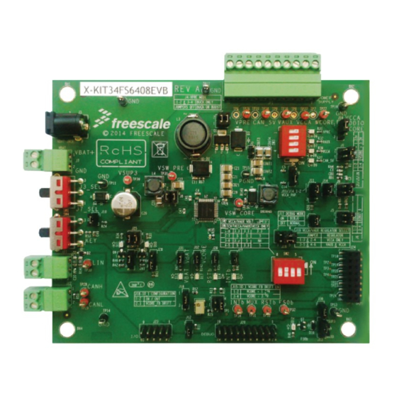
- Page 1 Freescale Semiconductor, Inc. Document Number: KT34FS6407-34FS6408UG Rev. 1.0, 8/2015 User’s Guide KIT34FS6407EVB and KIT34FS6408EVB Evaluation Board Figure 1. KIT34FS6407EVB and KIT34FS6408EVB Board © Freescale Semiconductor, Inc., 2015. All rights reserved.
-
Page 2: Table Of Contents
Contents Important Notice................3 Getting Started. -
Page 3: Important Notice
Important Notice Important Notice Freescale provides the enclosed product(s) under the following conditions: This evaluation kit is intended for use of ENGINEERING DEVELOPMENT OR EVALUATION PURPOSES ONLY. It is provided as a sample IC pre-soldered to a printed circuit board to make it easier to access inputs, outputs, and supply terminals. -
Page 4: Getting Started
Getting Started Getting Started Kit Contents/Packing List The KIT34FS6407EVB and KIT34FS6408EVB contents include: • Assembled and tested evaluation board/module in anti-static bag • Warranty card Jump Start Freescale’s analog product development boards help to easily evaluate Freescale products. These tools support analog mixed signal and power solutions including monolithic ICs using proven high-volume SMARTMOS mixed signal technology, and system-in-package devices utilizing power, SMARTMOS and MCU dies. -
Page 5: Terms
Terms Terms Part Number or Definition Parameter CAN_5V 5.0 V CAN voltage Evaluation Board FCCU Fault Collection and Control Unit FS0B Fail-safe Output Number 0 INTB Interrupt Input/Output Low-dropout Regulator RSTB Reset SMPS Switching Mode Power Supply SPIGen Software utility (installed on a PC) provides communication functions between the PC and a Freescale evaluation board Auxiliary power supply Power supply for ADC Pre-regulator voltage... -
Page 6: Getting To Know The Hardware
Getting to Know the Hardware Board Overview KIT34FS6407EVB and KIT34FS6408EVB evaluation boards demonstrate the functionality of the SMARTMOS MC34FS6407 and MC34FS6408 power system basis chips, respectively. These ICs are equipped with an intelligent power management system including safety features targeting the latest ISO26262 automotive functional safety standard. The EVB is a standalone board that can be used either with a compatible microcontroller or with a PC. - Page 7 Getting to Know the Hardware Board Description The EVB comes with either a Freescale MC34FS6407or MC34FS6408 IC mounted on it. Below is a view of the board indicating the major components. Buck/Buck Boost Section Power Supplies LEDs for Power Battery Supplies Connection Compensation...
- Page 8 Getting to Know the Hardware Table 2. Board Description (continued) Name Description • Simulate ignition key. Connected to IO_0 Ignition Key Switch • LIN bus as a master (Not available on KIT34FS640xEVB) LIN Bus • CANH and CANL differential pair CAN Bus •...
- Page 9 Getting to Know the Hardware KIT34FS640XEVB REV A 2015 FREESCALE Switch Jumper Red LED Green LED Figure 3. Default Board Configuration KT34FS6407-34FS6408UG User’s Guide Rev. 1.0 8/2015 Freescale Semiconductor, Inc.
- Page 10 Getting to Know the Hardware LED Definitions The following table lists the LEDs used as visual output devices on the EVB: Table 3. LEDs Schematic Name Description Label Indicator of pre-regulator voltage Indicator of auxiliary power supply Indicator of ADC power supply CAN_5V Indicator of 5.0 V CAN voltage IO_5...
- Page 11 Getting to Know the Hardware Table 4. Test Points (continued) Schematic Label Signal Name Description TP16 Ground TP17 Ground TP18 J24.2 TP19 J24.4 TP20 J24.6 TP21 J24.8 TP22 J24.10 TP23 J24.12 TP24 J24.14 TP25 J24.16 TP26 Pre-regulator voltage TP27 Core voltage for the MCU CORE TP28 CANH...
- Page 12 Getting to Know the Hardware Connector and Jumper Definitions Table 5. Main Power Supply Connector JP1 Pin Number Name of Power Rail Description Core voltage for the MCU CORE PGND Power ground ADC power supply Ground Auxiliary power supply Ground CAN_5V CAN power supply Ground...
- Page 13 Getting to Know the Hardware Table 6. Jumpers J1 through J31 (Including Connectors) (continued) Schematic Pin Number Pin Name Jumper/Pin Function Label Configuration for Boots_core pin Boots_core pin connected to GND – used for devices with linear voltage regulator on CORE Boots_core pin connected to SW_core –...
- Page 14 Getting to Know the Hardware Table 6. Jumpers J1 through J31 (Including Connectors) (continued) Schematic Pin Number Pin Name Jumper/Pin Function Label tracking DDIO tracks V DDIO tracks V DDIO CORE DBG_EN - enables debug mode Normal mode No jumper Debug mode DRIFT_MONIT –...
- Page 15 Getting to Know the Hardware Table 6. Jumpers J1 through J31 (Including Connectors) (continued) Schematic Pin Number Pin Name Jumper/Pin Function Label Additional Inputs/Output Fail-safe output FS0B VDDIO voltage DDIO MISO SPI – Master Input Slave Output Reset pin – connect to the reset line of the MCU RSTB MOSI SPI –...
- Page 16 Getting to Know the Hardware Table 6. Jumpers J1 through J31 (Including Connectors) (continued) Schematic Pin Number Pin Name Jumper/Pin Function Label General Inputs/Outputs pin1 IO_1 pin2 IO_0 pin3 IO_3 pin4 IO_2 pin5 IO_5 pin6 IO_4 pin7 VDDIO pin8 pin9 VBAT pin10 SPI/USB dongle or MCU connection...
- Page 17 Getting to Know the Hardware Table 6. Jumpers J1 through J31 (Including Connectors) (continued) Schematic Pin Number Pin Name Jumper/Pin Function Label INTB_LED_EN – enables LED D15 for INTB output IO5_OUT – IO_5 output configuration IO_5 connected to LED D10 via transistor Q5 IO_5 pulled down IO4_OUT –...
- Page 18 Getting to Know the Hardware 4.8.1 Compensation Network A voltage regulator needs feedback from the V voltage to be able to adjust (control) output voltage. For this reason, two bridges are CORE implemented in the external MC34FS6407 or MC34FS6408 circuitry. Static feedback (steady-state) voltage is defined by a simple resistor bridge (given by RA3/RB3 and RA4).
- Page 19 Getting to Know the Hardware 4.8.2 Second Resistor Bridge - V Monitoring DRIFT To increase the safety level of an application, a second resistor bridge has been added. This bridge generates the same voltage as the bridge connected to FB_core pin. If the difference between voltages is greater than V , the FS state machine is impacted.
- Page 20 Getting to Know the Hardware Switch Definitions Table 9. Switches Switch Number Position Function Description Power supply select Supply from J7 selected Power jack on J3 selected switch Only one choice is possible at the same time 3.3 V / 3.3 V 5.0 V / 5.0 V 3.3 V / 5.0 V This setting is not allowed if V...
-
Page 21: Accessory Interface Board
Accessory Interface Board Accessory Interface Board The KIT34FS6407EVB and KIT34FS6408EVB are generally used with the KITUSBSPIDGLEVME interface dongle (see Figure 6), which provides a bidirectional SPI/USB conversion. This small board makes use of the USB, SPI, and parallel ports built into Freescale’s MC68HC908JW32 microcontroller. - Page 22 Connecting the KITUSBSPIDGLEVME Interface Dongle A typical connection of KITUSBSPIDGLEVME Interface Dongle (see Section 5 "Accessory Interface Board") to the KIT34FS6407EVB or KIT34FS6408EVB evaluation board is done through connector J24 (see Figure 7). In this configuration, it is recommended that you use the EVB in a debug mode (J17 configured as Debug).
-
Page 23: Installing The Software And Setting Up The Hardware
Installing the Software and Setting up the Hardware Installing the GUI Software Two different Graphical User Interfaces (GUI’s) provide the software interface that allows you to communicate with the KIT34FS6407EVB or the KIT34FS6408EVB. • SPIGen is Freescale’s generic GUI for use with the KITUSBSPIDGLEVME Interface Dongle. - Page 24 Installing the Software and Setting up the Hardware Configuring the Hardware Figure 8 shows the setup required to use KIT34FS6407EVB or KIT34FS6408EVB. Power Supply USB Cable KITUSBSPIDGLEVME KIT34FS6407EVB/KIT34FS6408EVB KIT34FS6407EVB/34FS6408EVB Figure 8. Evaluation Board Setup 6.2.1 Step-by-step Instructions for Setting Up the Hardware Set up the KIT34FS6407EVB/KIT34FS6408EVB hardware and software as follows: 1.
- Page 25 Installing the Software and Setting up the Hardware Running the GUI With the KIT34FS6407/8 EVB’s, you are provided with two separate graphical user interfaces (GUI’s) that allow you to configure registers: • SPI generator (SPIGen) • MC3390X_GUI Both GUI’s are similar in function. You may use either one at your own discretion. 6.3.1 Running SPIGen To run SPIGen, do the following:...
- Page 26 Installing the Software and Setting up the Hardware In order to fill a specific need, it is also possible to edit registers with another value and to save it for further use, either as standalone or inside a batch. Figure 10 shows a batch called “RST_counter_to_0”, as an example.
- Page 27 Installing the Software and Setting up the Hardware 6.3.2 Running the MC3390X_GUI The MC3390X_GUI allows you to program all SPI features by using a friendly interface. Advanced users can also use MC3390X_GUI to modify the register table manually. To launch the MC3390X_GUI application, click on the application icon located either on your desktop or in Program Files menu as shown in Figure Figure 11.
- Page 28 Installing the Software and Setting up the Hardware Click on the “KIT3390xxEEVB” button on the left side of the screen. (See Figure 13.) Click Here Figure 13. MC3390X_GUI Configuration Selection A screen similar to the one in Figure 14 appears showing the status of the registers at startup. In this example, register INIT_FSSM2 has bit IO_23_FS configured as SAFETY CRITICAL.
- Page 29 Installing the Software and Setting up the Hardware 4. In the right side of the GUI, select NOT SAFETY and send the command as shown in Figure Figure 15. MC3390X_GUI Register KT34FS6407-34FS6408UG User’s Guide Rev. 1.0 8/2015 Freescale Semiconductor, Inc.
-
Page 30: Initialization And Configuration Mode
Debug Mode The KIT34FS6407EVB or KIT34FS6408EVB is mainly intended to be used in Debug mode. In Normal mode you must either use an MCU that is able to manage the WD or you must disable WD. If WD is enabled, you must send a valid WD response at startup. The response must occur within the 256 ms windows after reset release. -
Page 31: Schematic
Schematic Schematic Figure 16. Evaluation Board Schematic KT34FS6407-34FS6408UG User’s Guide Rev. 1.0 8/2015 Freescale Semiconductor, Inc. -
Page 32: Board Layout
Board Layout Board Layout Assembly Layer Top KIT34FS640XEVB REV A 2015 FREESCALE Figure 17. KIT34FS6407EVB/KIT34FS6408EVB Assembly Layer Top KT34FS6407-34FS6408UG User’s Guide Rev. 1.0 8/2015 Freescale Semiconductor, Inc. - Page 33 Board Layout Assembly Layer Bottom Figure 18. KIT34FS6407EVB/KIT34FS6408EVB Assembly Layer Bottom NOTE: This image is an exception to the standard top-view mode of representation used in this document. It has been flipped to show a bottom view. KT34FS6407-34FS6408UG User’s Guide Rev. 1.0 8/2015...
- Page 34 Board Layout Bill of Materials Table 11. Bill of Materials Item Schematic Label Value Manufacturer Part Number Assy Opt Active Components Freescale Semiconductor MC34FS6407 or MC34FS6408 Capacitors 680 pF KEMET C0603C681J5GAC 150 pF KEMET C0603C151J5GAC C4, C5, C14, C48, C49 0.1 μF KEMET C0603C104K3RAC...
- Page 35 PLUG_1X10 Phoenix contact 1803358 Inductors 22μH EPCOS B82479G1223M000 1.0 μH EPCOS B82472G6102M000 2.2 μH EPCOS B82472G6222M000 Transistors BUK9832-55A NXP Semiconductors BUK9832-55A,115 Q2, Q3 NJT4030P ON Semiconductor NJT4030PT3G Q5, Q6 MMBF0201NLT1 ON Semiconductor MMBF0201NLT1G BSS84LT1 ON Semiconductor BSS84LT1G Resistors 510 K...
- Page 36 Board Layout Table 11. Bill of Materials (continued) Item Schematic Label Value Manufacturer Part Number Assy Opt 11 K KOA Speer RK73H1JTTD1102F R31, R33, R34, R39, R40 1.5 K Bourns CR0603-JW-152ELF R32, R36, R37, R142 560 K KOA Speer RK73B1JTTD561J R35, R45, R46, R52 510 K KOA Speer...
-
Page 37: References
References References Following are URLs where you can obtain information on related Freescale products and application solutions: Freescale.com Support Description Pages KIT34FS6407EVB Tool Summary http://www.freescale.com/webapp/sps/site/prod_summary.jsp?code=KIT34FS6407EVB Page MC34FS6407 Product http://www.freescale.com/webapp/sps/site/prod_summary.jsp?code=MC34FS6407 Summary Page KIT34FS6408EVB Tool Summary http://www.freescale.com/webapp/sps/site/prod_summary.jsp?code=KIT34FS6408EVB Page MC34FS6408 Product http://www.freescale.com/webapp/sps/site/prod_summary.jsp?code=MC34FS6408 Summary Page... -
Page 38: Revision History
Revision History Revision History Revision Date Description of Changes 6/2015 • Initial Release 8/2015 • Corrected typo KT34FS6407-34FS6408UG User’s Guide Rev. 1.0 8/2015 Freescale Semiconductor, Inc. - Page 39 How to Reach Us: How to Reach Us: Information in this document is provided solely to enable system and software implementers to use Freescale products. Information in this document is provided solely to enable system and software implementers to use Freescale products. There are no express or implied copyright licenses granted hereunder to design or fabricate any integrated circuits based There are no express or implied copyright licenses granted hereunder to design or fabricate any integrated circuits based Home Page:...
Need help?
Do you have a question about the KIT34FS6407EVB and is the answer not in the manual?
Questions and answers