Table of Contents
Advertisement
Quick Links
Freescale Semiconductor
User's Guide
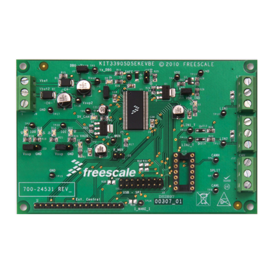
KIT33905 Evaluation Boards
Supports KIT33905D5EKEVBE (5 Volt)/KIT33905BD3EVBE (3.3 Volt)
Figure 1. KIT33905D5EKEVBE/KIT33905BD3EVBE Evaluation Boards
Table of Contents
1 Kit Contents / Packing List . . . . . . . . . . . . . . . . . . . . . . . . . . . . . . . . . . . . . . . . . . . . . . . . . . . . . . . . . . . . . . . . . . . . . . 2
2 Important Notice . . . . . . . . . . . . . . . . . . . . . . . . . . . . . . . . . . . . . . . . . . . . . . . . . . . . . . . . . . . . . . . . . . . . . . . . . . . . . . 3
3 Introduction . . . . . . . . . . . . . . . . . . . . . . . . . . . . . . . . . . . . . . . . . . . . . . . . . . . . . . . . . . . . . . . . . . . . . . . . . . . . . . . . . . 4
4 Required Equipment . . . . . . . . . . . . . . . . . . . . . . . . . . . . . . . . . . . . . . . . . . . . . . . . . . . . . . . . . . . . . . . . . . . . . . . . . . . 5
5 EVB Setup Configuration . . . . . . . . . . . . . . . . . . . . . . . . . . . . . . . . . . . . . . . . . . . . . . . . . . . . . . . . . . . . . . . . . . . . . . . 6
6 Hardware Configuration . . . . . . . . . . . . . . . . . . . . . . . . . . . . . . . . . . . . . . . . . . . . . . . . . . . . . . . . . . . . . . . . . . . . . . . . 7
7 Using the EVB. . . . . . . . . . . . . . . . . . . . . . . . . . . . . . . . . . . . . . . . . . . . . . . . . . . . . . . . . . . . . . . . . . . . . . . . . . . . . . . 11
8 Schematic Drawing . . . . . . . . . . . . . . . . . . . . . . . . . . . . . . . . . . . . . . . . . . . . . . . . . . . . . . . . . . . . . . . . . . . . . . . . . . . 17
9 Board Layout. . . . . . . . . . . . . . . . . . . . . . . . . . . . . . . . . . . . . . . . . . . . . . . . . . . . . . . . . . . . . . . . . . . . . . . . . . . . . . . . 18
10 Evaluation Board Bill of Material . . . . . . . . . . . . . . . . . . . . . . . . . . . . . . . . . . . . . . . . . . . . . . . . . . . . . . . . . . . . . . . . 20
11 References . . . . . . . . . . . . . . . . . . . . . . . . . . . . . . . . . . . . . . . . . . . . . . . . . . . . . . . . . . . . . . . . . . . . . . . . . . . . . . . . 21
© Freescale Semiconductor, Inc., 2011. All rights reserved.
Document Number: KT33905UG
Rev. 2.0, 9/2011
Advertisement
Table of Contents

Subscribe to Our Youtube Channel
Related Manuals for NXP Semiconductors Freescale KIT33905


Summary of Contents for NXP Semiconductors Freescale KIT33905
-
Page 1: Table Of Contents
Freescale Semiconductor Document Number: KT33905UG Rev. 2.0, 9/2011 User’s Guide KIT33905 Evaluation Boards Supports KIT33905D5EKEVBE (5 Volt)/KIT33905BD3EVBE (3.3 Volt) Figure 1. KIT33905D5EKEVBE/KIT33905BD3EVBE Evaluation Boards Table of Contents 1 Kit Contents / Packing List ..............2 2 Important Notice . -
Page 2: Kit Contents / Packing List
Kit Contents / Packing List Kit Contents / Packing List • KIT33905D5EKEVBE or KIT33905BD3EVBE Hardware • CD33905 (includes SPIGen Software) • CABLE, RIBBON FLAT 16 PIN ASSY, 0.100" PITCH, 6" LENGTH KIT33905 Evaluation Boards, Rev. 2.0 Freescale Semiconductor... -
Page 3: Important Notice
Important Notice Important Notice Freescale provides the enclosed product(s) under the following conditions: This evaluation kit is intended for use of ENGINEERING DEVELOPMENT OR EVALUATION PURPOSES ONLY. It is provided as a sample IC pre-soldered to a printed circuit board to make it easier to access inputs, outputs, and supply terminals. -
Page 4: Introduction
Introduction Introduction This evaluation board allows the user to implement the functionality of the MC33905 product System Basis Chip (SBC). This EVB includes two I/O test points that can be configured to be pulled up to V , or pulled down to GND through a resistor and indicator LED. -
Page 5: Required Equipment
Required Equipment Device Description/Features • Protected 5.0 V or 3.3 V regulators for MCU (part number selectable) and additional ICs (SPI configurable) with optional external PNP usage to increase current capability for MCU • Fully-protected embedded 5.0 V regulator for the CAN driver •... -
Page 6: Evb Setup Configuration
EVB Setup Configuration EVB Setup Configuration Figure 2. EVB Setup Configuration Diagram KIT33905 Evaluation Boards, Rev. 2.0 Freescale Semiconductor... -
Page 7: Hardware Configuration
Hardware Configuration Hardware Configuration KIT33905D5EKEVBE/KIT33905BD3EVBE operates with a single 5.5 V minimum power supply and can be driven with the KITUSBSPIDGLEVME along with its GUI. For added flexibility, it's also possible to develop a custom board to drive this evaluation board via the 16 pin standard header. Board Implementation For Standard EVB configuration, set up the jumpers as shown on Figure... - Page 8 Hardware Configuration Jumper Connections Name Description VDD Status Jumper closed -> LED indicator enabled source connection Jumper closed -> V connected to V MUX pin output Jumper closed -> external 2.4 kohm resistor pull-down to GND implemented I/O0 configuration 1-2 closed -> 4.7 kohm pull-down resistor to GND and indicator LED implemented 2-3 closed ->...
- Page 9 Hardware Configuration Power Supply and Input/Output Connectors The three pin terminal block (J9) serves as the main power terminal to supply a minimum of 5.5 V to operate KIT33905D5EKEVBE/KIT33905BD3EVBE. The CAN, LIN1, and LIN2 bus signals are accessible through the three pin terminal blocks J12, CON1, and CON2 respectively.
- Page 10 Hardware Configuration Connector J2 – SPI Control Pin # Pin Name Description TXDC CAN bus transmit data input. Internal pull-up to VDD Chip select pin for the SPI. When the CS is low, the device is selected. In Low Power mode with VDD ON, a transition on CS is a wake-up condition INTB This output is asserted low when an enabled interrupt condition occurs.
-
Page 11: Using The Evb
Using the EVB Using the EVB 1. Select Install SPIGen (setup.exe) from the CD33905 Start page and follow the on-screen installation instructions. 2. Connect power supply to the VBAT and GND terminals on the EVB and build the setup as shown on Figure 3. - Page 12 Using the EVB 7.1.1 Sending Commands to Read Flags Set on SBC Device Status and Flags sections Adds command to Sequential Mode sequence Adds all commands on tab to Sequential Mode sequence Read Device Mode – keeps Read device’s Flags SAFE f unctionality and exits Flags decoded and status...
- Page 13 Using the EVB 7.1.2 Reading and Writing Commands to Exercise SBC and Acquire Its Status Send a Simple Watchdog Hexadecimal value of SPI Device Selection Options to send SPI commands ‘Go to Normal Mode’ command command sent and received Stores commands sent General Flags in a text f ile Read General Flags...
- Page 14 Using the EVB 7.1.3 Sending Commands to Acquire the Configuration of the SBC Device Status and Flags sections Adds command to Sequential Mode sequence Adds all commands on tab to Sequential Mode sequence Read device status and Read Device Mode – keeps Device Status decoded enabled f unctionality SAFE f unctionality and exits...
- Page 15 Using the EVB 7.1.4 Sequential Mode Hexadecimal value of SPI Options to send SPI commands command sent and received Inserts a wait time in Stores commands sent millisecond increments in a text f ile Removes selected lines from list of commands Commands sent and received f rom the SBC’s MOSI and MISO pins...
- Page 16 Using the EVB 7.1.5 Automated State Diagram Mode Hexadecimal value of SPI Options to send SPI commands command sent and received Auto read f unction for Pre-configured selectable continuous device initialization and enabling mode status of device’s f eatures (Mouse over f or Information) Automated state diagram (Mouse over f or...
-
Page 17: Schematic Drawing
Schematic Drawing Schematic Drawing Figure 10. Schematic Drawing KIT33905 Evaluation Boards, Rev. 2.0 Freescale Semiconductor... -
Page 18: Board Layout
Board Layout Board Layout Assembly Drawing Figure 11. Assembly Drawing Top Side Layer Figure 12. Top Side Layer KIT33905 Evaluation Boards, Rev. 2.0 Freescale Semiconductor... - Page 19 Board Layout Bottom Side Layer Figure 13. The Bottom Side Layer KIT33905 Evaluation Boards, Rev. 2.0 Freescale Semiconductor...
-
Page 20: Evaluation Board Bill Of Material
Evaluation Board Bill of Material 10 Evaluation Board Bill of Material Item Schematic Label Value Description Vender Mfg. PN CON1, CON2, J9, J12 PCB 3WAY 250V/16A CON 3 TB TH 5MM SN CAMDEN ELEC- CTB5000/3 TRONICS LTD C1, C3, C6, C19, C20 0.1 UF CAP CER 0.1UF 50V 10% X7R 0805 KEMET... -
Page 21: References
References 11 References You can obtain information on other Freescale products and application solutions by going to the following URLs: Description Data Sheet www.freescale.com/files/analog/doc/data_sheet/MC33903_4_5.pdf Fact Sheet www.freescale.com/files/analog/doc/fact_sheet/MC33903_4_5FS.pdf Application Note www.freescale.com/files/analog/doc/app_note/AN3865.pdf Errata http://www.freescale.com/files/analog/doc/errata/MC33903_4_5ER.pdf SPIGen www.freescale.com/files/soft_dev_tools/software/device_drivers/SPI- Gen.html Freescale’s Web Site www.freescale.com Freescale’s Analog Web Site www.freescale.com/analog Freescale’s Power Management Web Site www.freescale.com/powermanagement... - Page 22 How to Reach Us: Home Page: www.freescale.com Web Support: http://www.freescale.com/support USA/Europe or Locations Not Listed: Freescale Semiconductor, Inc. Technical Information Center, EL516 2100 East Elliot Road Tempe, Arizona 85284 1-800-521-6274 or +1-480-768-2130 www.freescale.com/support Europe, Middle East, and Africa: Freescale Halbleiter Deutschland GmbH Technical Information Center Schatzbogen 7 81829 Muenchen, Germany...
Need help?
Do you have a question about the Freescale KIT33905 and is the answer not in the manual?
Questions and answers