Table of Contents
Advertisement
Quick Links
Advertisement
Table of Contents

Related Manuals for Synthes MAXFRAME AUTOSTRUT


Summary of Contents for Synthes MAXFRAME AUTOSTRUT
- Page 1 MAXFRAME AUTOSTRUT™ Multi-Axial Correction System Physician User Manual...
-
Page 3: Table Of Contents
4. Surgical Technique 5. Care and Maintenance 6. Software Updates or Patches 7. Symbols Glossary 8. Specifications 9. Product Information 10. Standards and compliance for EMC Image intensifier control ■ Notes ▲ Precautions ▲ WARNINGS MAXFRAME AUTOSTRUT™ System • Physician User Manual... -
Page 4: Welcome
MAXFRAME AUTOSTRUT control system and hexapod strut usage, MAXFRAME AUTOSTRUT Software operation and the assembly instructions for use in conjunction with the DePuy Synthes MAXFRAME Multi-Axial Correction System. ■ Note: The following terms all refer to the MAXFRAME AUTOSTRUT hardware and software described in this user’s document:... -
Page 5: Introduction
2.1 MAXFRAME AUTOSTRUT System assembly and MAXFRAME AUTOSTRUT Software use. Features and Benefits MAXFRAME AUTOSTRUT System consists of both hard- MAXFRAME AUTOSTRUT System enables: ware and software components as follows: • Highly accurate frame adjustments. • MAXFRAME AUTOSTRUT Hexapod Struts •... - Page 6 If the patient plan to travel on an System hardware and software. airplane, the security metal detector will alarm • MAXFRAME AUTOSTRUT is not to be used for and may interfere with the MAXFRAME diagnosis. AUTOSTRUT System functionality. Patient •...
- Page 7 MAXFRAME Quick Adjust or Standard struts. The original MAXFRAME System is MR conditional; please see its IFU for specific conditions. 2.8 Software Requirements In order to install the MAXFRAME AUTOSTRUT Soft- ware, the physician will need administrator privileges on the computer. • Operating system:...
-
Page 8: Product Description
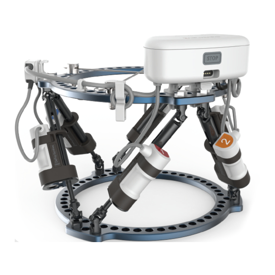
MAXFRAME AUTOSTRUT System components are com- patible with the DePuy Synthes MAXFRAME Multi-Axial Correction System (“MAXFRAME”). The MAXFRAME Figure 1: MAXFRAME AUTOSTRUT hexapod struts without motor System hardware is coupled with the MAXFRAME Soft- (struts are attached to frame rings in operating room; OR) ware for use in the creation of patient treatment plans, which detail required strut adjustments. - Page 9 (each cable splitter is connected to two struts). Figure 4: MAXFRAME AUTOSTRUT control system and 6 MAXFRAME AUTOSTRUT hexapod struts assembled on MAXFRAME System rings (outside of a sterile environment).
- Page 10 3. Product Description The system indicators include: 3.1.3 Instruments 3.2 Software MAXFRAME AUTOSTRUT System utilizes the following MAXFRAME AUTOSTRUT Software is used by the instruments: physician. • Wrench B 8.0/11.0 mm • Torque Wrench 10 Nm Applications of the software include: • 3 mm Allen Wrench 1.
-
Page 11: Surgical Technique
Open MAXFRAME AUTOSTRUT strut packaging and verify that it is not damaged and that the manual knob is inserted to its position. MAXFRAME AUTOSTRUT™ System • Physician User Manual... - Page 12 4. Surgical Technique 2. Strut Assembly in the operating room 2.1. Orient the MAXFRAME AUTOSTRUT Strut so that the motor socket is facing outward and the blue manual knob is facing away from where the control unit is going be mounted.
- Page 13 • Remember that both ends of the strut should be locked to the rings. Rotate the knob until you are at the right length. MAXFRAME AUTOSTRUT™ System • Physician User Manual...
- Page 14 5 mm hex that mates with the internal recess on the head of the shoulder bolt. • Remember that both ends of the strut should be locked to the rings. Physician User Manual • MAXFRAME AUTOSTRUT™ System...
- Page 15 Wrench, 10 Nm could damage the strut. Using the Torque Wrench, 10 Nm, tighten the shoulder bolt in both sides of the strut until you feel the wrench slip, indicating it has reached the appropriate torque. MAXFRAME AUTOSTRUT™ System • Physician User Manual...
- Page 16 Expiration date is related to the battery. Open the control box package and follow the instructions listed at the inner side of the cover. Physician User Manual • MAXFRAME AUTOSTRUT™ System...
- Page 17 Take out the control box ring interface. Attach control box ring interface with the 2 Allen screws by using 3 mm Allen key. You can place it in any free space near the master tab. MAXFRAME AUTOSTRUT™ System • Physician User Manual...
- Page 18 4. Surgical Technique Carefully pull out the control system with the 6 motors attached to it. Slide the control box onto the box interface until it clicks in place. Verify that it can’t slide back. Physician User Manual • MAXFRAME AUTOSTRUT™ System...
- Page 19 Snap the two cable splitters into their place on the upper ring. You can place them in any free space near the connection with the side struts. It is preferred to place them as close to the control box as possible. MAXFRAME AUTOSTRUT™ System • Physician User Manual...
- Page 20 If the motor is too close, release the bolt screw that locks the strut, rotate the strut so that the motor does not touch the ring, and lock again with the torque wrench. (See upper view picture.) Physician User Manual • MAXFRAME AUTOSTRUT™ System...
- Page 21 Please keep at least one knob for future use (such as strut size replacement). Verify that motor number 1 is positioned in the correct strut according to the MAXFRAME plan. Check that motor numbers are continuous from 1 to 6 counter-clockwise. MAXFRAME AUTOSTRUT™ System • Physician User Manual...
- Page 22 4. Surgical Technique Place and snap cable wrapper in a free space on both sides of the upper ring. Wrap excess cable around the cable wrapper. Physician User Manual • MAXFRAME AUTOSTRUT™ System...
- Page 23 If needed, attach free cable to free rings holes with the cable clips. MAXFRAME AUTOSTRUT™ System • Physician User Manual...
- Page 24 4. Surgical Technique Keep strut lockers, 3 mm Allen key and motor clip tool for the end of the treatment. You are now ready for system activation. Physician User Manual • MAXFRAME AUTOSTRUT™ System...
- Page 25 If you do not have a MAXFRAME 3D II Software user account, click “Request a User Account” and you will be redirected to the MAXFRAME 3D II landing page where you can request an account. MAXFRAME AUTOSTRUT™ System • Physician User Manual...
- Page 26 USB cable to the Control System. This is useful for training or familiarizing yourself with the software functionality. Do not check this box if you desire to upload a treatment program to the Control System. Physician User Manual • MAXFRAME AUTOSTRUT™ System...
- Page 27 New Treatment Select New Treatment If the device has a prior treatment plan loaded, it will be stopped. This Resume Treatment notice is displayed and the “Resume Treatment” button will appear in the header. MAXFRAME AUTOSTRUT™ System • Physician User Manual...
- Page 28 (A check will appear if each motor test passes.) After all motors passed, press the top right arrow to move to the next step. If the battery is low, a warning message is displayed. Physician User Manual • MAXFRAME AUTOSTRUT™ System...
- Page 29 Upload patient treatment plan. Only MAXFRAME treatment plans within strut size short, medium and long are allowed. Treatment plans containing X-Short and XX-Short strut sizes will be rejected. Approve patient name. MAXFRAME AUTOSTRUT™ System • Physician User Manual...
- Page 30 Review and approve selected treatment plan. Select the number of segmentations per day (up to 20) and treatment time according to patient’s daily activity. Verify that the time refers to patient time zone. Physician User Manual • MAXFRAME AUTOSTRUT™ System...
- Page 31 The treatment plan will not load until all areas in yellow are fixed. View treatment graphics display and verify that it is linear, has no “jumps” nor irregular pattern and that it generally makes sense from clinical aspect. MAXFRAME AUTOSTRUT™ System • Physician User Manual...
- Page 32 Upload treatment plan. When uploading or downloading data from the device, you will see a rapid blinking orange light. The data transfer may take some time. When the data transfer is complete, the light will stop blinking. Physician User Manual • MAXFRAME AUTOSTRUT™ System...
- Page 33 When initiating a replan, if desired, surgeon can move the struts to the nearest integer value as defined in the MAXFRAME Software replan by utilizing manual soft- ware mode or manual adjustment knob. MAXFRAME AUTOSTRUT™ System • Physician User Manual...
- Page 34 Press the “manual mode” button to open the relevant screen. Select the desired strut and the movement direction and press on the relevant button. Each press will move the selected strut 0.25 mm in the desired direction. Physician User Manual • MAXFRAME AUTOSTRUT™ System...
- Page 35 When uploading or downloading data from the device, you will see a rapid blinking orange light. The data transfer may take some time. When the data transfer is complete, the light will stop blinking. MAXFRAME AUTOSTRUT™ System • Physician User Manual...
- Page 36 ▲ Precaution: The patient and/or post operative care team must be capable of understanding the system operation, indicators (lights/sounds) made throughout the treatment, and provide timely communications back to their surgeon. Physician User Manual • MAXFRAME AUTOSTRUT™ System...
- Page 37 If the patient has pressed the emergency stop button, and the physician has determined that the System should be started again, a new PDF treatment plan will need to be created and uploaded to address the residual deformity. MAXFRAME AUTOSTRUT™ System • Physician User Manual...
- Page 38 After clearing the emergency stop button, proceed to “New Treatment” in the software to begin the process of loading the new treatment plan on the device. Physician User Manual • MAXFRAME AUTOSTRUT™ System...
- Page 39 (for example: struts MAXFRAME AUTOSTRUT Control System and Struts and replace with MAXFRAME do not move/dead system, Quick Adjust or Standard Struts. The MAXFRAME AUTOSTRUT System is backwards hardware failure, or unable compatible with the manual struts found within MAXFRAME Multi-Axial Correction to upload treatment plan.)
- Page 40 Prior to strut removal, reinforcement of the frame with the MAXFRAME System Strut Swap Kit is required. Refer to the MAXFRAME System surgical technique for details. Instruments 03.311.007 Wrench 8.0/11.0 mm 03.312.851 Torque Wrench, 10 Nm 01.312.012 Strut Swap Kit Physician User Manual • MAXFRAME AUTOSTRUT™ System...
- Page 41 According to the defined activation clock, verify that the replacement is not performed during the next session. Release the relevant motor by taking out its clip using clip tool. MAXFRAME AUTOSTRUT™ System • Physician User Manual...
- Page 42 With torque wrench, 10 Nm, tighten the shoulder bolt until you feel the wrench slip, indicating it has reached the appropriate torque. Ensure that the wrench is fully seated. Physician User Manual • MAXFRAME AUTOSTRUT™ System...
- Page 43 If removed motor activates during a strut swap proce- dure, physician will need to determine if the missed strut movement is of clinical significance and adjust the strut manually with the blue knob before reinstalling the motor. MAXFRAME AUTOSTRUT™ System • Physician User Manual...
- Page 44 Wrench, 10 Nm could damage the strut. Using the Torque Wrench, 10 Nm, tighten the shoulder bolt in both sides of the strut until you feel the wrench slip, indicating it has reached the appropriate torque. Physician User Manual • MAXFRAME AUTOSTRUT™ System...
- Page 45 Instead of the motor, a gear locker must be inserted into each of the struts. Instruments Motor clip tool 3 mm Allen key MAXFRAME AUTOSTRUT™ System • Physician User Manual...
- Page 46 Then release the control box interface from the upper ring. Release the relevant motor by taking out its clip using clip tool Release all 6 motors. Physician User Manual • MAXFRAME AUTOSTRUT™ System...
- Page 47 Release wire attachments and cable splitters from the ring. MAXFRAME AUTOSTRUT™ System • Physician User Manual...
- Page 48 4. Surgical Technique Press down control box release button and pull out the control box. Unlock the screws holding the control box interface. Physician User Manual • MAXFRAME AUTOSTRUT™ System...
- Page 49 Place upper part in place according to adaptor contour. Then insert the locking pin from the opposite side and press it against the upper part till “click” is heard and both parts are fully attached to the adaptor body. MAXFRAME AUTOSTRUT™ System • Physician User Manual...
-
Page 50: Care And Maintenance
For more information, please refer to “Care and Maintenance” section in MAXFRAME System Surgical Technique. ■ Note: Dispose of equipment at the end of service life in accor- dance with your local regulations. Physician User Manual • MAXFRAME AUTOSTRUT™ System... -
Page 51: Software Updates Or Patches
• Such software updates and patches will be released according to Manufacturer’s procedures and will adhere to all regulations. • User will be prompted to download updates or patches to the software as needed when logging in. MAXFRAME AUTOSTRUT™ System • Physician User Manual... -
Page 52: Symbols Glossary
Indicates a medical device that should not age is damaged be used if the package has been damaged or opened. ISO 15223-1 5.7.10 Unique Device Indicates a carrier that contains Unique Device Identifier Identifier information. (Barcode) Physician User Manual • MAXFRAME AUTOSTRUT™ System... - Page 53 To indicate that the product shall be separated in accordance with equipment when disposed. article 11(2) of Direc- tive 2002/96/EC (WEEE) Rating – – Rated power input/ To indicate a d.c. rated power input/battery battery, d.c. MAXFRAME AUTOSTRUT™ System • Physician User Manual...
-
Page 54: Specifications
87 g Control Box (LWH) 110 × 60 × 50 600 g 8.2 Storage Conditions Temperature range: –30 °C to +60 °C/–22 °F to +140 °F 8.3 Operating Conditions Temperature range: 5 °C to 40 °C/41 °F to 104 °F Physician User Manual • MAXFRAME AUTOSTRUT™ System... - Page 55 Declarations Guidance and manufacturer’s declaration – electromagnetic emissions The MAXFRAME AUTOSTRUT System is intended for use in the electromagnetic environment specified below. The customer or the user of the MAXFRAME AUTOSTRUT System should assure that it is used in such an environment.
- Page 56 8. Specifications Guidance and manufacturer’s declaration – electromagnetic immunity MAXFRAME AUTOSTRUT System is intended for use in the electromagnetic environment specified below. The customer or the user of the MAXFRAME AUTOSTRUT System should assure that it is used in such an environment.
- Page 57 Guidance and manufacturer’s declaration – electromagnetic immunity MAXFRAME AUTOSTRUT System is intended for use in the electromagnetic environment specified below. The customer or the user of the MAXFRAME AUTOSTRUT System should assure that it is used in such an environment.
- Page 58 W outside ISM in ISM bands 800 MH 2.5 GHz bands d = [ ]P d = [ ]P d = [ ]P d = [ ]P 0.01 0.12 0.37 0.64 1.17 11.7 Physician User Manual • MAXFRAME AUTOSTRUT™ System...
- Page 59 1970 LTE Band 1, 3, 4, 25; UMTS 2450 2400–2570 Bluetooth, Pulse WLAN, modulation 802.11 b/g/n, 217 Hz RFID 2450, LTE Band 7 5240 5100–5800 WLAN 802.11 Pulse modulation 5500 217 Hz 5785 MAXFRAME AUTOSTRUT™ System • Physician User Manual...
-
Page 60: Product Information
Strut – medium 1100011-01 MAXFRAME AUTOSTRUT™ Hexapod Strut – long 1100007-01 MAXFRAME AUTOSTRUT™ Automated Hexapod Control System Kit 1100022-01 MAXFRAME AUTOSTRUT™ Automated Hexapod Accessories 1110005-01 MAXFRAME AUTOSTRUT™ Software 01.314.000 MAXFRAME AUTOSTRUT™ Hexapod Strut Set Physician User Manual • MAXFRAME AUTOSTRUT™ System... -
Page 61: Standards And Compliance For Emc
(EMC) for this type of product, if used for the intended purposes. Such standards and regulations define the electro- magnetic emissions level coming from the product and the requested immunity against electromagnetic inter- ferences from external sources. MAXFRAME AUTOSTRUT™ System • Physician User Manual... - Page 64 Distributed by: An Affiliate of DePuy Synthes Synthes GmbH 13 Hayetzira St. Yokneam Luzernstrasse 21 Business Park Israel 4528 Zuchwil Switzerland www.depuysynthes.com © DePuy Synthes Trauma, a division of Synthes GmbH. 2022. All rights reserved. OrthoSpin Document #IFU-0140 Rev. C 07/2022...
Need help?
Do you have a question about the MAXFRAME AUTOSTRUT and is the answer not in the manual?
Questions and answers