Table of Contents

Related Manuals for horsch Terrano 4.3 GX


Summary of Contents for horsch Terrano 4.3 GX
- Page 1 OPERATING INSTRUCTIONS Terrano 4.3 | 4.4 | 5.3 | 5.4 | 6.3 | 6.4 GX TRANSLATION OF THE ORIGINAL OPERATING INSTRUCTIONS READ CAREFULLY PRIOR TO STARTING UP! KEEP OPERATING INSTRUCTIONS IN A SAFE PLACE! 60084498 • 01 • 06/2022 • en...
-
Page 3: Table Of Contents
Table of contents Table of contents 1 Introduction ............................Foreword ..............................Notes on representation........................... 1.2.1 Warning notes ..........................1.2.2 Instructions ..........................2 Safety and responsibility ........................10 Intended use ............................10 Operating Instructions ..........................10 Qualification of personnel ........................11 2.3.1 Groups of operators........................ - Page 4 Table of contents Lighting..............................38 Instruction stickers ........................... 39 6 Assembly groups........................... 41 Tines ................................ 41 MulchMix coulter ............................. 42 Packer ..............................44 Levelling discs............................47 Levellers ..............................50 7 Optional equipment ..........................56 Brake system ............................56 7.1.1 Pneumatic brake .......................... 56 7.1.2 Hydraulic brake..........................
- Page 5 Table of contents 10 Disposal ..............................105 10.1 Decommissioning ............................. 105 11 Service ..............................106 12 Appendix ..............................107 12.1 Tightening torque............................. 107 12.1.1 Metric screws (Nm) ........................107 12.1.2 Metric screws (ft.lb) ........................108 12.1.3 Inch screws (Nm) ......................... 109 12.1.4 Inch screws in (ft lb) ........................110 60084498 •...
- Page 6 Die HORSCH Maschinen GmbH, Sitzenhof 1, D-92421 Schwandorf, erklärt hiermit in alleiniger Verantwortung als Hersteller, dass das nachfolgend genannte Produkt: Grubber Typ: Terrano 4.3 GX, Terrano 4.4 GX, Terrano 5.3 GX, Terrano 5.4 GX, Terrana 6.3 GX, Terrano 6.4 GX den einschlägigen grundlegenden Sicherheits- und Gesundheitsanforderungen der Richtlinie 2006/42/EG entspricht.
- Page 7 Please enter the corresponding data into the following list upon reception of the machine: Serial number: Machine type: Year of construction: Initial use: Accessories: Dealer address Name: Road: Place: Phone: Cust. No. Dealer: Cust. No. HORSCH 60084498 • 01 • 06/2022 • en...
-
Page 8: Introduction
Observe the safety notes! HORSCH will not assume liability for any damage or malfunctions resulting from fail- ure of complying with the operating instructions. Any person commissioned to performing tasks on or with the machine must read and apply the operating instructions. -
Page 9: Instructions
Introduction | 1 CAUTION Highlights a danger that can lead to injury if not avoided. Read all warning notes in these operating instructions! 1.2.2 Instructions NOTE Identifies important notes. Instructions for actions and their elements are marked by different symbols: ü... -
Page 10: Safety And Responsibility
• carrying out maintenance and/or repair work on a machine that has not been shut down or is not secured against restarting HORSCH does not assume any liability for damages resulting from the unintended use of the machine. 2.2 Operating Instructions... -
Page 11: Qualification Of Personnel
• Operation • Maintenance • Troubleshooting and repair Operator trained by Furthermore, for certain activities the corresponding personnel must have been trained by service personnel from HORSCH. HORSCH This refers to the following activities: • Loading and transport • Commissioning... -
Page 12: Children In Danger
2 | Safety and responsibility • Troubleshooting and repair • Disposal Certain work concerning maintenance and repair must only be carried out by an ex- pert workshop. Such work is identified with the additional comment Workshop work. 2.4 Children in danger Children are not able to assess dangers and may behave unpredictably. -
Page 13: Brake System
Safety and responsibility | 2 Ø For machines without brake select the weight of the tractor and the speed so that the machine can be managed securely under all conditions. Remember the extended breaking distance. For road transport the machine must be set to transport position. The machine must have been folded up and secured, see chapter Folding in and Connecting and Trans- port position. -
Page 14: Commissioning
Ø The machine must only be put into operation after receiving instructions by employees of the authorized dealer or a HORSCH employee. All protective features and safety equipment, such as detachable protective devices (wheel chocks, etc.), must be correctly in place and reliably functioning before the machine is put into operation. -
Page 15: Hydraulics
Safety and responsibility | 2 2.7.5 Hydraulics The hydraulic system is under high pressure. The machine's hydraulics has several functions, which can cause injury to persons or damage to the machine if operated incorrectly: • Escaping fluid may penetrate the skin. •... -
Page 16: Overhead Lines
2 | Safety and responsibility To avoid resulting dangers, the following points must be observed: Ø When parking the machine, sufficient distance to buildings and other ma- chines/vehicles must be ensured Ø For longer road travel, stop after 2 hours the latest and fold in the machine again (see section Folding) 2.7.6 Overhead lines When unfolding or folding in the wings, the machine may reach the height of over-... -
Page 17: Use In The Field
2.7.9 Changing equipment / wear items Ø Only pulling tools may be attached that meet the technical requirements ac- cording to these operating instructions. HORSCH does not assume any liability for damages resulting from the attachment of non-fitting pulling tools as well as incorrect mounting. -
Page 18: Retrofitting And Conversions
Structural changes not approved by HORSCH may affect the functionality and opera- tional safety of the machine and will void any warranty claim. HORSCH is not liable for damages to life and limb as well as property damages res- ulting from unapproved retrofitting and conversions. -
Page 19: Danger Zone
All other maintenance and repair tasks, which are not described in the operating in- structions, must only be carried out by an authorized professional workshop or by an operator who has been trained by HORSCH for this purpose. 2.8 Danger zone... -
Page 20: Safety Stickers
2 | Safety and responsibility Failing to pay attention to the danger zone can result in severe or even fatal physical injuries. 1. Do not stand under lifted loads. Lower such loads to the ground first. 2. Instruct persons to leave the danger zone around the machine and tractor be- fore any machine movements. - Page 21 Safety and responsibility | 2 Secure the machine with wheel chocks before uncoupling or parking. 00381116 No passengers are allowed to ride on the machine! 00380054 Keep sufficient distance to electric high voltage power lines. 00385791 When connecting the machine and when operating the hy- draulics, no persons are allowed between the machines! 00380145 Stay clear of the operating range of foldable machine...
-
Page 22: Positions Of Safety Stickers
2 | Safety and responsibility In order to prevent eye injuries, do not look directly at the beam area when the radar sensor is switched on! 00380894 The pressure accumulator is charged with gas or oil pres- sure. Dismantle and repair only in strict compliance with the instructions in the technical manual. -
Page 23: Commissioning
3 Commissioning NOTE These work activities may be carried out only by persons trained by HORSCH for this purpose. WARNING Increased danger of accidents during commissioning. Ø Observe the notes in the Safety chapter and familiarise yourself with the ma- chine! 3.1 Delivery... -
Page 24: Installation
3 | Commissioning 3.3 Installation Instruction of the operator and initial installation of the machine will be carried out by our service engineers or distributors. Any preceding use of the machine is prohibited! The machine can only be released for operation after the instruction session conduc- ted by service technicians or sales partners and after the operating instructions have been read. -
Page 25: Technical Data
4 Technical data 4.1 Technical data Machines with 3-bar tine Terrano 4.3 GX 5.3 GX 6.3 GX section Working width 4.00 m 4.90 m 5.90 m [13'1"] [16'1"] [19'4"] Transport width 2.99 m 2.99 m 2.99 m [9'10"] [9'10"] [9'10"] Transport height 2.90 m 3.40 m 3.90 m [9'6"] [11'2"] [12'10"] Length 8.50–9.30 m 8.50–9.30 m 8.50–9.30 m... - Page 26 4 | Technical data Machines with 4-bar tine Terrano 4.4 GX 5.4 GX 6.4 GX section Working width 4.00 m 4.90 m 5.90 m [13'1"] [16'1"] [19'4"] Transport width 2.99 m 2.99 m 2.99 m [9'10"] [9'10"] [9'10"] Transport height 2.90 m 3.40 m 3.90 m [9'6"] [11'2"] [12'10"] Length 9.35–10.10 m 9.35–10.10 m 9.35–10.10 m [30'8"–30'2"] [30'8"–30'2"]...
- Page 27 Technical data | 4 Dimensions Terrano GX Dimensions in mm (*1) (*2) Terrano 4.3 GX 8500 2990 2900 4000 9300 Terrano 4.4 GX 9350 2990 2900 4000 10100 Terrano 5.3 GX 8500 2990 3400 4900 9300 Terrano 5.4 GX 9350 2990 3400 4900 10100 Terrano 6.3 GX 8500 2990 3900 5900 9300 Terrano 6.4 GX 9350...
-
Page 28: Type Plate
The type plate with the CE marking is located on the frame or the hopper of the ma- chine. Data on the type plate: Sitzenhof 1 Made in Germany D-92421 Schwandorf Maschinen GmbH www.horsch.com A-0: A-1: A-2: A-3: Model designation Serial number... - Page 29 Technical data | 4 Ø Verify the suitability of the tractor before commissioning. The tractor must meet the following requirements to be able to use the machine as intended: Implement attachment Terrano 4.3 GX 4.4 GX 5.3 GX 5.4 GX 6.3 GX 6.4 GX Adjustable drawbar –...
-
Page 30: Calculating The Ballasting
4 | Technical data 4.3.1 Calculating the ballasting The permissible total weight, the permissible axle loads and the tyre load bearing ca- pacity must not be exceeded when mounting or connecting implements. The front axle of the tractor must always be loaded with at least 20 % of the curb weight of the tractor. - Page 31 Technical data | 4 Calculations 1. Calculation of minimum front ballasting with rear implement: ∙ ( + ) − ∙ + 0,2 ∙ ∙ Enter the result into the table. 2. Calculation of minimum rear ballasting with front implement ∙ − ∙...
- Page 32 4 | Technical data Checking the calculations Check the calculated values additionally by weighing: Weigh the combination of tractor and towed or connected machine to determine the front and rear axle load. Compare the determined values with the calculated values. This includes: •...
-
Page 33: Attachment
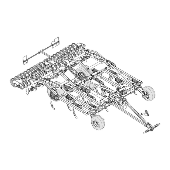
5 Attachment 5.1 Overview Example: Machine type Terrano 5.4 GX Implement attachment Hose bracket Support wheels Hydraulic cylinder for drawbar / traction intensifier Tine field, 3/4-beam Undercarriage Levelling discs Packer Lighting 5.2 Hydraulics WARNING Danger of serious accidents and injuries from unintentional hydraulic movements! Ø... -
Page 34: Marking Of Hydraulic Hoses
5 | Attachment NOTE Ø The machine is operated with mineral-based hydraulic oil. Do not mix mineral oils with organic or ester oils. The hydraulic circulation of the tractor or the hydraulic unit must contain min- eral-based hydraulic oil. Ø Oil purity acc. to ISO 4406: 18/16/13 Ø... -
Page 35: Lock Valves
Attachment | 5 Folding Tools 1 NOTE The following hydraulic movements are carried out via the hoses marked with +: Lift Folding in Retraction of cultivation tools 5.2.2 Lock valves The lock valves in the area of the drawbar are used to activate or lock different ma- chine functions. - Page 36 5 | Attachment 1. Lock the lock valve after parking the machine: Turn the lever perpendicular to the hydraulic line. 2. Open the lock valve for road travel and use in the field: Turn the lever parallel to the direction of the hydraulic line Lock valve traction intensifier Lock valve traction intensifier...
-
Page 37: Aluminium Clips
Attachment | 5 5.3 Aluminium clips The aluminium clips are plugged on the piston rods of hydraulic cylinders depending on the operating states. Different aluminium clips The thickness of the clips differs according to colour: Colour blue yellow black Silver Thickness 7 mm 10 mm... -
Page 38: Lighting
5 | Attachment 5.4 Lighting 7-pin plug Rear light, right Lamp, blinker Lamp, tail light Lamp, brake light Rear light, left Lamp, brake light Lamp, tail light Lamp, blinker Number Designation Colour Function yellow Blinker left 54 g white Earth green Blinker right 58 R... -
Page 39: Instruction Stickers
Attachment | 5 5.5 Instruction stickers 1. Clean soiled stickers. 2. Damaged or illegible stickers must be replaced immediately. 3. Apply the specified stickers to spare parts. Jack lifting point 00385971 00385971 Check the tyre pressure at regular inter- vals, adapt if necessary - see mainten- ance overview. - Page 40 50 km or 10 hours – see maintenance overview. 00380359 Lashing points Hook fastening gear (lashing belts, chains, etc.) here. Loading work only by operators trained by HORSCH! 60010418 00385757 60010418 Eurasische Zollunion (Eurasian Tariff Union) 60021384 60084498 • 01 • 06/2022 • en...
-
Page 41: Assembly Groups
Ø Replace the spring assembly only as a complete unit (workshop work). Ø Never open the spring assembly. Ø If a tine is blocked or jammed by stones etc., please contact the HORSCH Ser- vice. The blockage may give way and the tine jump forward into its normal position. -
Page 42: Mulchmix Coulter
6 | Assembly groups NOTE The stone release protection serves as protection system against obstacles in the field. Ø Reduce the working depth if the stone release protection is often triggered under hard ground conditions, even without stones as obstacles. 6.2 MulchMix coulter WARNING Danger of injury caused by machine lowering... - Page 43 Changing the coulter and ULD coulter (coulter tips, guide plates, wings): Ø Use only original HORSCH wear items. Ø Use new screws and nuts with each replacement. Ø Check for correct seating of the four-cornered shaft coulter screws in the coulter tips and guide plates: 60084498 •...
-
Page 44: Packer
6 | Assembly groups Ø Observe the sequence when tightening MulchMix coulter tips together with guide plates: Ø Tighten the screw connections for mounting the wings on the nut. Do not tighten on the screw head. Ø Tighten all screw connections with a nut runner or torque spanner. Ø... - Page 45 Assembly groups | 6 OptiRoll Packer The profiled rubber rings together with their large diameter (Ø 73 cm) provide a good self-propelling function. As a result, the packer does not tend much to pushing up and blocking on light and sandy locations. RingFlex Packer RingFlex Packer (example: Single version) The RingFlex Packer is available in two different designs:...
- Page 46 6 | Assembly groups Heavy steel ring packer with excellent consolidation on heavy, dry soils. For medium and heavy soils with stones. Breaks-up and consolidates down to deeper layers. Very good cutting effect. SteelFlex Packer Heavy packer with strip-type consolidation and high mixing effect on heavy, dry soils.
-
Page 47: Levelling Discs
Assembly groups | 6 Double RollFlex Packer Double RollFlex Packer Very good self-cleaning due to the natural resonance of the leaf springs. Deep-act- ing consolidation with high mixing effect from the soil movement in the packer. Cage roller Example: Pipe rod roller Particularly suitable light and medium soils with a tendency to forming a bow wave in front of the packer. - Page 48 6 | Assembly groups Levelling discs with screw adjustment 1 Screw adjustment 2 Cotter pin (with crank and scale) 3 Crank (folding) 4 Levelling disc 5 Scale Please note: Turn the crank always in alternating fashion and uniformly to prevent cocking! Ø...
- Page 49 Assembly groups | 6 1. Loosen the screws. 2. Depending on the required angle of attack (1), position the upper screw in one of the 3 holes (2). 3. Tighten the screws. 4. Adjust all levelling discs equally. Adjusting the border disc Border disc 1 Border disc 2 Bolt and cotter pin...
-
Page 50: Levellers
6 | Assembly groups Replacing levelling discs Levelling discs 1. Lower the machine on the packer. 2. Extend the hydraulic cylinder of the drawbar and the undercarriage com- pletely. 3. Fill up the hydraulic cylinder of the drawbar with aluminium clips. 4. - Page 51 Assembly groups | 6 Example: Levellers on the packer 1 Levellers 2 Screw adjustment 3 Packer WARNING Danger of serious injuries from falling or lowering machine parts during adjustment and conversion tasks. Ø Instruct persons to leave the danger zone. Ø...
- Page 52 6 | Assembly groups Adjust the height of the levellers Levellers 1 Leveller 2 Screw adjustment (with crank and scale) 3 Crank (folding) 4 Cotter pin 5 Scale Please note: Turn the crank always in alternating fashion and uniformly to prevent cocking! 1.
- Page 53 Assembly groups | 6 Positioning/changing the levellers Fastening the levellers 1 Fastening screw 2 Clamping plate 3 Leveller 4 Pole 5 Clamping screws on the bar Remove/install and position the leveller 1. Remove the mounting screw on the clamping plate. 2.
- Page 54 6 | Assembly groups Intermediate springs 1 Intermediate spring 2 Adjustment fixture 3 Packer Adjust angle of attack of the intermediate springs Intermediate springs and adjustment fixture 1 Intermediate spring 2 Lever 3 Row of holes (with bolt and cotter pin) 60084498 •...
- Page 55 Assembly groups | 6 Please note: Modify the settings always incrementally and alternating to prevent cocking! 1. Lift the bar if necessary. 2. Pull out the cotter pin and remove the bolt. 3. Adjust the required angle on the lever. 4.
-
Page 56: Optional Equipment
NOTE Adjustments and repair work on the brake system must only be carried out in a pro- fessional workshop or by an operator, who has been specially trained by HORSCH. 7.1.1 Pneumatic brake Overview... - Page 57 Optional equipment | 7 The tractor must always be secured with the parking brake when connecting. Connecting the brake 1. First connect the coupling head “Brake” (yellow). 2. Then connect the coupling head "Provision" (red). The tractor must be secured with the parking brake when unhitching. Unhitch the brake 1.
- Page 58 7 | Optional equipment Ø Clean the filters in the coupling heads whenever required, but at least once every year. Ø To ensure the function of the valves, anti-freeze should be added to the com- pressed air. Follow the operating instructions of the tractor! Ø...
- Page 59 Danger of traffic accidents! Ø Maintenance and adjustment tasks on the brake are workshop work and may only be carried out by qualified personnel! Refer to the pertaining HORSCH Service instructions. Ø Changes to the pressure setting cause changes in the response characteristics of the brake system.
-
Page 60: Hydraulic Brake
7 | Optional equipment 7.1.2 Hydraulic brake The hydraulic line controls the brake power on the brake cylinders. The brake inlet pressure must not exceed 150 bar. Overview Hydraulic brake 1 Hydraulic coupling for brake 2 Drain valve 3 Breakaway valve for emergency 4 Pressure accumulator operation 5 Wheel cylinder... - Page 61 Optional equipment | 7 3. Release the parking brake. The cables must be relieved, and the wheels must be free to rotate. 4. Fill the pressure accumulator for emergency braking by pressing the brake pedal. To do so, fully depress the brake pedal on the tractor for approx. 10 seconds.
-
Page 62: Minidrill
7 | Optional equipment 7.2 MiniDrill The tillage machine can be equipped in addition with the fine seed unit MiniDrill to increase the impact force and to save additional passes. It consists, amongst others, of hopper, metering drive, fan and electric control mod- ule. - Page 63 Optional equipment | 7 Access steps WARNING Danger of falls and injuries due to insufficiently stable access ladder! Ø Always make sure that access ladder and foldable support are correctly moun- ted before stepping on the ladder. Ø Only step on the access steps after they have properly engaged. Ø...
-
Page 64: Harrow
7 | Optional equipment 7.3 Harrow The Terrano GX machine can be equipped in addition with a harrow behind the Packer. The harrow loosens and levels the surface and distributes any harvest residues. Harrow on the packer With the two bolts (see arrow) in front of and behind the pivot point the harrow Setting movement can be limited upwards and downwards. -
Page 65: Crossbar
Optional equipment | 7 Harrow on the double packer Maintenance The harrow is maintenance free. The harrow attachment on the tool carrier must be checked for tightness after the initial 10 operating hours and before the start of the season. The entire harrow unit is mounted to or disassembled from the packer frame using Assembly/disassembly the U-straps and the pertaining washers and nuts. -
Page 66: Fertiliser Distributor
7 | Optional equipment The crossbar is adjusted purely mechanically via the hole pattern. Setting 1. Remove the cotter pin and pull out the bolt. 2. Adjust the desired inclination. The higher the hole is chosen, the more intens- ive do the tines work. 3. - Page 67 Optional equipment | 7 Fertiliser distributor (sample Tiger 4 MT) 1 Hose system 2 Distributor tower Fertiliser is directed to the tines via distributor tower and hose system. Tines with fertiliser pipe 3 Fertiliser pipe 4 Tines In use, the distributor tower must be aligned vertically to ensure even distribution across the width of the machine.
- Page 68 7 | Optional equipment Maintenance WARNING Danger of injury when working on the distributor Ø Always call for a second person to assist. Ø Use suitable accessing steps. 1. Check the distributor regularly for foreign objects. 2. Check connections and hoses every day for leakages. Repair or replace worn or damaged hoses immediately.
- Page 69 Optional equipment | 7 Flap to adjust the fertiliser placement 1. Press the flap (A) together and let it snap into place at the desired position. 2. Adjust the flaps on all tines equally. Three positions of the flap Position 1: Placement in the soil Position 2: Placement on the field surface Position 3: Placement in the soil and on the field surface 60084498 •...
-
Page 70: Operation
8 Operation WARNING Ø Whenever working on the machine pay attention to the associated safety notes in the chapter "Safety and Introduction" as well as the accident preven- tion regulations! 8.1 Initial commissioning/tractor change During initial commissioning and when changing the tractor, the machine must be adapted to the tractor. -
Page 71: Connecting
Operation | 8 WARNING Leaking hydraulic fluid can cause serious injuries! Danger of injury by unwanted machine movements. Ø Connect and disconnect the hydraulic lines only when the hydraulics are without pressure on both tractor and machine. 8.2.1 Connecting The machine must be properly connected to a tractor before any machine move- ments. - Page 72 8 | Operation Machines with tractor link arm: • Engage the machine. • Insert the securing device of the catching hooks. • Lock the tractor link arms against movement sideways. Machines with ball and socket coupling: • Connect hydraulic lines of the hydraulic cylinder to the drawbar. •...
-
Page 73: Transport Position
Operation | 8 8.2.2 Transport position WARNING Danger of traffic accidents Before driving off: Ø Clean all picked up soil from the entire machine. Ø Check function of lighting system. Ø Lock the control units mechanically or electrically, depending on the version, during transport travel. - Page 74 8 | Operation Terrano 4.3 GX and 4.4 GX Applies only to these machine types. First, adjust the two front lighting carriers for road transport: 5. Loosen cotter pin and bolt (2). 6. Push both lighting carriers (1) to the outside. 7. Secure the new position of the lighting carriers with bolt and cotter pin. Position of control units Position Floating position...
-
Page 75: Parking
Operation | 8 8.2.3 Parking DANGER Serious accidents from loss of stability! Ø Park the machine only on a level and firm ground. Ø Staying under unsecured raised machine parts is prohibited. Ø Carry out work on raised machine parts only if they are mechanically suppor- ted with suitable means. - Page 76 8 | Operation The machine can be parked in a hall or under a roof either folded or unfolded. Park the machine as low as possible when folded. In case of longer parking periods, preferably park the machine unfolded on the packer to prevent damage to the tyres.
-
Page 77: Folding
Operation | 8 8.2.4 Folding WARNING Serious crushing due to lowering / dropping machine parts Ø No persons may stay under raised machine parts. Ø Order persons to leave the danger zone around the machine. Make sure be- fore folding that no persons are present in the danger zone. Ø... -
Page 78: Depth Setting
8 | Operation All Terrano machine types 4. Lower the undercarriage to lift the machine. 5. Adjust the oil flow rate on the control unit of the tractor. 6. Slow the control unit before the machine components reach the stop position. 7. - Page 79 Operation | 8 Adjusting the working depth 1. Unfold the machine, see Folding section. 2. Operate the control unit and adjust the machine to the desired working depth. Observe the scale (0–30) at this. The aluminium clips for depth setting are plugged on the setting bars. The clips may Manual depth setting only be removed, respectively inserted when the respective side is relieved.
- Page 80 8 | Operation Example: Setting rod with aluminium clips on the packer Increasing the working depth 4. Slightly lift the machine. 5. Remove clips from the area (1). 6. Lower the machine. 7. Plug on clips again in the area (2). Reducing the working depth 8.
-
Page 81: Traction Intensifier
Operation | 8 8.4 Traction intensifier If traction intensifiers are enabled, part of the load caused by the bottom pull will al- ways be transferred to the tractor. 1. Disable traction intensifiers prior to connecting and unhitching, on loose soils or shallow cultivation. -
Page 82: Position Of Control Units During Use In The Field
8 | Operation Headland 1. Lift the machine before turning at the headland. The machine turns on the packer. The support wheels should be just above the ground. 2. Lower the machine. Switch the control unit to floating position. Position of control units Floating position Locked position during use in the field... -
Page 83: Checks
Operation | 8 8.5.2 Checks The working quality essentially depends on the adjustments and checks made prior to and during use, as well as on regular care and maintenance of the machine. Ø Carry out all maintenance tasks and adjustments before starting to work. NOTE Ø... -
Page 84: Care And Maintenance
The machine has been designed and built to offer maximum performance, economy and operator friendliness under a vast variety of operating conditions. Prior to delivery, the machine was checked at the factory and by the HORSCH sales partner to ensure the optional condition of the machine. -
Page 85: After 10 Operating Hours
Care and maintenance | 9 9.1.1 After 10 operating hours Maintenance location Work instructions All threaded, plug, and hy- Retighten all threaded, plug and hydraulic connections. draulic connections Event tight threaded and hydraulic connection may become loose due to material de- terioration or paint residues between the threaded joints or unions. -
Page 86: During The Season
9 | Care and maintenance Maintenance location Work instructions WARNING! Lower all hydraulically lifted parts (e.g. wings, packer, undercarriage, etc.) to the ground before performing any work on the hydraulic system. Depressurise the hydraul- ics on the tractor and implement side! Empty the pressure accumulators. Refer to the pressure accumulator item. - Page 87 Care and maintenance | 9 Electrics Electric lines Check for damage 40 h Hydraulics Hydraulic system and com- Check all hydraulic components and hoses for function, leak tight- 40 h ponents ness, fastening and chafing. Hydraulic brake Brake system Check condition and function. daily Brake lines and hoses Check for damages as well as crushing and kinking.
-
Page 88: At The End Of The Season
9 | Care and maintenance 9.1.4 At the end of the season Maintenance location Work instructions Complete machine Perform care and cleaning work; do not spray plastic parts with oil or similar. Spray the piston rods of the hydraulic cylinder with a suitable corrosion protection agent. - Page 89 Care and maintenance | 9 Check spherical cap for wear 5. Check possibly existing wear limits on the hold-down of the tractor. Replace the hold-down if necessary. Wear limit on the hold-down 6. Lubricate the ball socket as needed. Ø Adjust the distance of the hold-down to the ball to max. 0.5 mm. After each connecting Ø...
-
Page 90: Drawbar Eye
9 | Care and maintenance max. 0,5 mm Ø Secure the hold-down with bolt and cotter pin. Ø Place the protective cap on the ball. After unhitching 9.3 Drawbar eye Ø Check mounting screws for firm seating. Ø Replace the component concerned if one of the wear limits has been ex- ceeded or fallen short of (workshop work): Designation Nominal dimension (mm) -
Page 91: Coulter/Tines Terra Grip 3L
Care and maintenance | 9 9.4 Coulter/tines Terra Grip 3L Ø See maintenance overview After 10 operating hours WARNING Danger of severe injuries caused by the tensioned spring assembly Ø Never open the screw (1) on the spring assembly. 550 +/- 50 Nm 60 +/- 10 Nm 350 +/- 50 Nm 9.5 Direction of installation of the guide plates... - Page 92 9 | Care and maintenance Guide plate right NOTE Ø Observe the correct direction of installation when replacing deflectors! Overview of guide plate The following figures show the mounting direction of the guide plates on the tines according to the machine type and direction of travel (A). arrangement Terrano 4.3 GX Terrano 4.3 GX...
- Page 93 Care and maintenance | 9 Terrano 4.4 GX Terrano 4.4 GX Arrangement of the guide plates in relationship to the direction of travel (A) 60084498 • 01 • 06/2022 • en...
- Page 94 9 | Care and maintenance Terrano 5.3 GX Terrano 5.3 GX Arrangement of the guide plates in relationship to the direction of travel (A) 60084498 • 01 • 06/2022 • en...
- Page 95 Care and maintenance | 9 Terrano 5.4 GX Terrano 5.4 GX Arrangement of the guide plates in relationship to the direction of travel (A) 60084498 • 01 • 06/2022 • en...
- Page 96 9 | Care and maintenance Terrano 6.3 GX Terrano 6.3 GX Arrangement of the guide plates in relationship to the direction of travel (A) 60084498 • 01 • 06/2022 • en...
-
Page 97: Packer
Care and maintenance | 9 Terrano 6.4 GX Terrano 6.4 GX Arrangement of the guide plates in relationship to the direction of travel (A) 9.6 Packer Ø Check the packer bearings for firm seating. Ø Check the packer shafts for free rotation. Ø Check packer segments for wear, deformation and breakage. Ø... - Page 98 9 | Care and maintenance Perform this action on all packer bearings: 1. Place the inside screw (1), outside screw (2) and bearing into each other. 2. Slide the conical ring (3) on the outer screw. 3. Screw the conical nut (4) on the inside screw. 4.
- Page 99 Care and maintenance | 9 9. Bolt the packer shaft together with the spacer (6) to the side arm (7). Dismantling the packer WARNING Dropping or rolling machine parts can cause severe crushing injuries, etc.! Ø Support the raised machine by appropriate means and secure the packer against rolling away.
-
Page 100: Checking Brake Linings
Ø Check the wheel nuts regularly for tight fit. Ø Check the tyre pressure regularly while the tyres are cold. Ø Pay attention to the chapter Maintenance. Ø Use only tyres and rimes approved by HORSCH. 60084498 • 01 • 06/2022 • en... -
Page 101: Changing Wheels
Care and maintenance | 9 9.8.1 Changing wheels WARNING Traffic and work accidents from improper mounting! Ø Perform the wheel change only when the machine is hitched to the tractor and in stable position. Ø Never park the machine without securing it when the wheel(s) is/are dis- mantled! Ø... -
Page 102: Clean The Machine
9 | Care and maintenance 9. Attach the new wheel and fasten it. Tighten all wheel nuts crosswise: etc. 10. Remove the tripod trestle and lower the machine. 11. Tighten the wheel nuts with the torque wrench. NOTE Retighten the wheel nuts after 10 km. 9.9 Clean the machine Ø... -
Page 103: Lubricating The Machine
Care and maintenance | 9 9.10 Lubricating the machine Ø Lubricate the machine regularly and after each wash with a suitable grease gun. If in place, temporarily removed the covering caps. Regular maintenance secured the machines readiness for use, reduces repair costs and avoids downtimes. -
Page 104: Machine Storage
9 | Care and maintenance Overview of lubrication points (example of Terrano 5.4 GX) Lubrication points with the addition "2x" can be found on either side of the ma- chine. 9.11 Machine storage The following steps must be followed if the machine is to be shut down for a longer period of time: 1. -
Page 105: Disposal
Attention must be paid to all valid regulations! Decommissioning and waste disposal must only be carried out by operators who have been trained by HORSCH. Contact a waste disposal company, if this should be necessary. 60084498 • 01 • 06/2022 • en... -
Page 106: Service
The customers' satisfaction with the machine and the company are of prime import- ance to HORSCH. The service staff of our sales partners and the service employees of HORSCH will al- ways be available for assistance with problems. The service staff require the following information to correct technical defects as quickly as possible: •... -
Page 107: Appendix
12 Appendix 12.1 Tightening torque NOTE Ø The tightening torques only serve as guidelines and are generally valid. Actual data given at the corresponding points in the operating instructions have pri- ority. Ø Screws and nuts must not be treated with lubricants, since this would change the friction value. -
Page 108: Metric Screws (Ft.lb)
12 | Appendix 1.50 1090 3.00 1080 1240 2.00 1160 1360 3.00 1000 1570 1840 2.00 1200 1700 1990 3.50 1500 2130 2500 2.00 1060 1670 2370 2380 12.1.2 Metric screws (ft.lb) Tightening torques – metric screws in ft.lb Size Pitch Screw design –... -
Page 109: Inch Screws (Nm)
Appendix | 12 1.50 248.56 306.83 482.37 687.41 803.94 376.16 3.00 282.49 349.60 548.75 796.57 914.58 2.00 309.78 382.79 600.38 855.57 1,003.08 3.00 418.94 518.51 737.56 1,157.97 1,357.11 2.00 453.60 560.55 885.08 1,253.86 1,467.75 3.50 569.40 733.87 1,106.34 1,571.00 1,843.91 2.00 626.93 781.82 1,231.73 1,748.02 1,755.40... -
Page 110: Inch Screws In (Ft Lb)
12 | Appendix 12.1.4 Inch screws in (ft lb) Tightening torques – inch screws in ft.lb Screw diameter Strength 2 Strength 5 Strength 8 No marks on head 3 marks on head 6 marks on head Inch Coarse Fine Coarse Fine Coarse Fine... - Page 111 Notes 60084498 • 01 • 06/2022 • en...
- Page 112 60084498 • 01 • 06/2022 • en...
- Page 114 All details on technical specifications and illustrations are approximate and non-binding. Subject to technical product revisions. HORSCH MASCHINEN GmbH Phone: +49 94 31 7143-0 Sitzenhof 1 Fax: +49 94 31 7143-9200 92421 Schwandorf, Germany Email: info@horsch.com...
Need help?
Do you have a question about the Terrano 4.3 GX and is the answer not in the manual?
Questions and answers