
Related Manuals for horsch Joker 7 RT+


Summary of Contents for horsch Joker 7 RT+
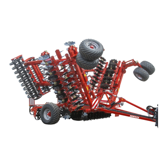
- Page 1 OPERATING INSTRUCTIONS Joker 5 6 7 8 RT TRANSLATION OF THE ORIGINAL OPERATING INSTRUCTIONS READ CAREFULLY PRIOR TO STARTING UP! KEEP OPERATING INSTRUCTIONS IN A SAFE PLACE! ART.: 60043780 ISSUE: 02/2021...
-
Page 3: Machine Identification
HORSCH: ..............Confirmation of receipt of machinery Warranty claims become only effective when the first use of the machine is reported to HORSCH Maschinen GmbH within a week. www.horsch.com under SERVICE PARTNERBEREICH an interactive PDF form is available for down- load for this purpose (not available in all languages). -
Page 4: Eg-Konformitätserklärung
EG-Konformitätserklärung HORSCH Maschinen GmbH Sitzenhof 1, D-92421 Schwandorf erklärt hiermit in alleiniger Verantwortung als Hersteller, dass das nachfolgend genannte Produkt: Scheibenegge Joker 5 RT Typ: Joker 6 RT Joker 7 RT+ Joker 8 RT den einschlägigen grundlegenden Sicherheits- und Gesundheitsanforderungen der Richtlinie 2006/42/EG entspricht. -
Page 6: Table Of Contents
Table of contents Introduction ...........4 Operation .............33 Foreword ............4 Commissioning / Tractor change .........33 Notes on representation .........4 Adapting the hose connection ....33 Service............5 Connecting/Parking ........34 Warranty claim processing ......5 Connecting ...........34 Consequential damage........5 Transport position .........36 Safety and responsibility ......6 Parking ............38 Intended use ...........6 Folding ............39... - Page 7 Care and Maintenance .......56 Cleaning ............56 Lubricating the machine .......56 Maintenance intervals........57 Storage ............57 Maintenance overview ........58 Wheels and tyres ........62 Changing wheels (undercarriage) ....62 Waste disposal ...........64 Appendix .............65 Tightening torques ........65 Index ............67...
-
Page 8: Introduction
DANGER to the safety notes! Highlights a danger that will lead to death or HORSCH will not assume liability for any dam- severe injury if it is not avoided. age or malfunctions resulting from failure of complying with the operating instructions. -
Page 9: Service
Service Consequential damage HORSCH Company would like you to be com- The machine has been manufactured by pletely satisfied with your machine and our HORSCH with greatest care. However, despite services. the intended use deviations in placing quantity up to total failure may be caused by e.g.: If you encounter any problems, please feel free to contact your sales partner. -
Page 10: Safety And Responsibility
Please read and comply with the following safety Horsch does not assume any liability for dam- notes, before you start to use the machine! ages resulting from the unintended use of the machine. -
Page 11: Qualification Of Personnel
The person is acquainted with the function of ¾ service personnel from HORSCH. This refers to the machine within the scope of its work and the following activities: is able to assess and avoid any work related dangers. -
Page 12: Children In Danger
Children in danger Safety in traffic Children are not able to assess dangers and may DANGER behave unpredictably. Children are therefore especially endangered: No passengers are allowed to ride on the machine! Keep children away from the machine. ¾ Especially before drive off and before trigger- ¾... -
Page 13: Safety In Operation
The machine must only be put into operation by a qualified expert workshop. ¾ after receiving instructions by employees of the authorized dealer or a HORSCH em- Coupling and unhitching ployee. Send the acknowledgement of receipt per ¾... -
Page 14: Pressure Accumulator
Check all lines, hoses and screwed con- workshop or by an operator, who has been nections regularly for leaks and any visible specially trained by HORSCH. external damage! Allow hydraulic oil and hydraulic components ¾... - Page 15 Use in the field Do not leave the cabin. ¾ Do not touch any metal objects. ¾ Do not create a conductive connection to DANGER ¾ ground. No passengers are allowed to ride on the Warn persons: DO NOT come near the ma- ¾...
-
Page 16: Fertiliser And Dressed Seed
Caution! Danger of injury caused by projecting ¾ claim. parts (e.g. coulters)! Assume ergonomic working postures with any HORSCH is not liable for damages to life and ¾ assembly work. limb as well as property damages resulting from unapproved retrofitting and conversions. -
Page 17: Care And Maintenance
This by an operator who has been trained by can lead to accidents with severe or even fatal HORSCH for this purpose. physical injuries. Conform to prescribed schedules for repetitive ¾... -
Page 18: Danger Zone
Danger zone Failing to pay attention to the danger zone can The area marked red indicates the danger zone result in severe or even fatal physical injuries. of the machine: Do not stand under lifted loads. Lower such ¾ loads to the ground first. Instruct persons to leave the danger zone ¾... -
Page 19: Safety Stickers
Safety stickers Safety stickers on the machine warn of hazards Clean soiled safety stickers. ¾ at dangerous points and are an important part Damaged or illegible safety stickers must be ¾ of the safety equipment of the machine. Miss- replaced immediately. ing safety stickers increase the risk of severe or Affix the specified safety stickers on spare ¾... - Page 20 Secure the machine with wheel chocks before uncoupling or parking. 00381116 Shut the engine down and pull off the key before starting maintenance and repair work. 00380294 Remaining in the danger zone is only permitted when the lifting cylinder pin is inserted. 00380896...
- Page 21 Position of the safety stickers (depending on equipment) 00385757 (8 RT) Safety stickers with the addition “2x” can be found on either side of the machine.
-
Page 22: Commissioning
If the machine is hitched up in two-point mode, ¾ These work activities may be carried out only by the tractor link arms must be blocked against persons trained by HORSCH for this purpose. swinging sideways. On a trailer or low loader the machine must ¾... -
Page 23: Technical Data
The type plate with the CE marking is located on the frame of the machine. Data on the type plate: Sitzenhof 1 Made in Germany D-92421 Schwandorf Maschinen GmbH www.horsch.com A-0: A-1: A-2: A-3: 1. Model designation 2. Serial number 3. - Page 24 Joker RT with single packer 6958 2950 (Figures: Joker 6 RT)
- Page 25 Joker RT with double packer 7560 2950 (Figures: Joker 6 RT)
- Page 26 Joker RT with double packer and crossbar (cutting blade roller option) 7560 2950 (Figures: Joker 6 RT)
-
Page 27: Requirements For The Tractor
Requirements for the tractor WARNING Risk of accident! Observe the permissible values of the tractor ¾ for axle loads, total weight, tyre load bearing capacity and air pressure. Verify the suitability of the tractor before com- ¾ missioning. The tractor must meet the following require- ments to be able to use the machine as intended: Implement attachment Joker... -
Page 28: Brake Connections
Electrics Electric power supply 12 V Lighting Socket, 7-pin, acc. to ISO 1724, see chapter Lighting Hydraulics Maximum system pressure 210 bar Oil grade Mineral hydraulic oil Number of dual-acting control units 3 (Basic equipment) (Joker 5/6 RT / 7 RT+) +1 with CrossBar front (option) +1 with Cutting blade roller front (option) +1 hydraulic depth setting (option) -
Page 29: Construction
Construction Overview Joker 5/6 RT 7 RT+ 1 Connecting 8 Packer (here: Double RingFlex Packer) 2 Hose bracket 9 Undercarriage 3 Support 10 Lighting 4 Support wheel (depending on equipment) 11 Hydraulic cylinder, undercarriage 5 Crossbar or cutting blade roller (depending on the 12 Hydraulic cylinders for flaps equipment) 13 Hydraulic cylinder for drawbar... -
Page 30: Construction
Construction Overview Joker 8 RT 1 Connecting 8 Packer (here: Double RingFlex Packer) 2 Hose bracket 9 Undercarriage 3 Support 10 Lighting 4 Support wheel (depending on equipment) 11 Hydraulic cylinder, undercarriage 5 Crossbar or cutting blade roller (depending on the 12 Hydraulic cylinders for flaps equipment) 13 Hydraulic cylinder for drawbar... -
Page 31: Hydraulics
Hydraulics Marking of hydraulic hoses Symbols on the handles of the hydraulic cou- plings indicate the function of the respective WARNING hoses: Unintentional hydraulic movements may lead to severe accidents and injuries! Secure or lock the control units on the tractor. ¾... - Page 32 Crossbar Cutting blade roller Hydraulic brake...
-
Page 33: Aluminium Clips
Aluminium clips The aluminium clips are placed on the piston CAUTION rods of hydraulic cylinders, depending on the operating states, see chapter Operation. Danger of damage to the packer frame. Depending on the design, do not remove any ¾ fixed clips or depth limitations! NOTE Pay attention to the ratio on the machine, see ¾... -
Page 34: Lighting
Lighting WARNING Traffic accidents caused by defective lighting. Ensure cleanliness and tight fit of the plug-and- ¾ socket connections. Check the lighting before setting off. ¾ Check warning boards and lighting equipment ¾ for cleanliness. 7-pin plug Rear light, right Lamp, blinker Lamp, taillight Lamp, brake light... -
Page 35: Instruction Stickers
Instruction stickers Clean soiled stickers. ¾ Damaged or illegible stickers must be ¾ replaced immediately. Apply the specified stickers to spare parts. ¾ Retighten the wheel nuts / wheel bolts after Exceeding the permissible vehicle width! 50 km or 10 hours. Retighten every day - Swivel the cutting blade roller inward before see maintenance overview. - Page 36 Lock valve position Lashing points; Hook fastening gear (lashing belts, chains, 1 Field work (open) etc.) here. 2 Road travel (closed) 60010418 00385757 Jack lifting point; area where the jack must be attached for 00380878 the wheel change. Align the drawbar horizontally with alumini- um clips.
-
Page 37: Operation
Operation Adapting the hose connection Adapt the hose bracket and the hose length to Whenever working on the machine the tractor. pay attention to the associated safety notes in the chapter "Safety and The hoses should be routed here in such a way prevention of accidents"... -
Page 38: Connecting/Parking
Connecting/Parking Connecting The machine must be properly connected to a tractor before any machine movements. DANGER There is a risk that persons may become crushed and severely injured between machine DANGER and tractor! Serious accidents caused by the machine roll- Instruct persons to leave the area between ¾... - Page 39 Support Machines with tractor link arm hitching: - Engage the machine. The support is height-adjustable. - Insert the securing device of the catching hooks. Unfold the crank and select the desired gear ¾ - Lock the tractor link arms against move- (1): ment sideways.
-
Page 40: Transport Position
5. Insert clips on both hydraulic cylinders of the Transport position undercarriage: Joker 5/6/8 RT Joker 7 RT+ WARNING Transport height 300 mm clips 250 mm clips ≤ 4.0 m Danger of road accidents caused by losing the Transport height 4.2 m 300 mm clips machine or machine parts. - Page 41 Position of control units during road travel Floating position Locked position Position Control unit Folding Lift/lower (undercarriage) Drawbar Working depth Crossbar Cutting blade roller Tractor link arm...
-
Page 42: Parking
Parking WARNING Always park the machine on the supports! DANGER Risk of accident through uncontrolled snapping Serious accidents caused by the machine roll- upward or dropping of the drawbar! ing away! Always close the lock valve on the hydraulic ¾ Park the machine on a flat, paved surface. -
Page 43: Folding
8. Uncouple the machine mechanically. 2. Open the lock valve on the hydraulic cylinder of the drawbar. 9. Shut the lock valve on the hydraulic hose of the cutting blade roller (optional). 3. Fully raise the machine using the hydraulic cylinders on the undercarriage and drawbar. -
Page 44: Manual Depth Setting
Manual depth setting Always fill all adjustment areas (1) and (2) ¾ completely with clips, if this is possible. For the manual depth setting, the working depth Place clips not needed in area (3). ¾ is adjusted with aluminium clips. The aluminium Align the machine or the disc rows as hori- clips for depth setting are plugged on the setting ¾... -
Page 45: Hydraulic Depth Setting (Option)
Hydraulic depth setting (option) With the hydraulic system the working depth can also be set and adjusted while working in the field. Levelling The hydraulic cylinders are connected in the rephasing system (connected in series). Therefore by depth changes the machine always moves parallel to the working surface. -
Page 46: Manual Depth Setting
Manual depth setting For the manual depth setting, the working depth is adjusted with aluminium clips. Insert the alu- minium clips into the hydraulic cylinders of the depth setting. The aluminium clips are plugged on the setting bars. Adjusting the working depth Hydraulic cylinder for depth setting Extend the cylinders for the depth setting ¾... -
Page 47: Use In The Field
Use in the field You should only lower the undercarriage if ¾ the machine becomes stuck because of the prevailing soil conditions. Unfold the machine in the field and adjust; see ¾ chapter Depth setting. Checks Open the lock valve on the hydraulic cylinder ¾... - Page 48 Position of control units during use in the field Floating position Locked position Position Control unit Folding Lift/lower (undercarriage) Drawbar Working depth Crossbar Cutting blade roller Tractor link arm...
-
Page 49: Assembly Groups
Assembly groups The position of the support wheel is deter- ¾ mined by the clips in the area (1). By default, 50 mm aluminium clips are placed. Support wheels Note the ratio of approx. 1:1.5 with the Joker ¾ 5/6 RT. Example: To adjust the support wheel approx. -
Page 50: Discsystem
DiscSystem Maintenance The bearings of the discs are filled with grease ¾ The two rows of the serrated discs cuts through and therefore principally maintenance-free. the harvest residues and the soil and mixes the Check the bearings regularly for clearance, harvest residues in down to working depth. -
Page 51: Packer
Packer WARNING The packers may continue to turn when step- ping on them causing falls with serious injuries. Do not step on the packers. ¾ NOTE Double RingFlex Packer Clean the packers regularly during work when ¾ The twin packer is fasted to the packer carrier soil attaches to it. -
Page 52: Optional Equipment
Coupling head “Brake” yellow Coupling head “Provision” red workshop or by an operator, who has been Pipe filter specially trained by HORSCH for this purpose. Trailer brake valve with brake pressure regulator and parking brake Air reservoir Drain valve Spring brake cylinder 1 Anschluß... -
Page 53: Maintenance
Unhitch NOTE 1. The tractor must be secured with the parking Before parking the machine pull the parking ¾ brake when unhitching. brake button down again to apply the parking 2. First disconnect the coupling head “Provi- brake. sion” (red). 3. -
Page 54: Brake Valve Unit
Maintenance and adjustment tasks on the • brake are workshop work and may only be carried out by qualified personnel! Refer to the pertaining HORSCH Service instructions. Changes to the pressure setting cause chang- • es in the response characteristics of the brake system. -
Page 55: Hydraulic Brake
Hydraulic brake The hydraulic line controls the brake power to the master brake cylinder. The master brake cylinder uses brake fluid to forward the pressure to the wheel cylinders. The brake inlet pressure must not exceed 130 bar. The brake system is equipped with a breaking away coupling. -
Page 56: Parking Brake
Parking brake Unhitch 1. Park the machine. 2. Apply the parking brake. 3. Place wheel chocks under the wheels. DANGER 4. Loosen the brake line. Uncontrolled rolling of the machine can cause 5. Disconnect the break-away cable from the severe injuries by crushing or rolling over. tractor. -
Page 57: Crossbar
Crossbar Cutting blade roller The crossbar can be installed before the The cutting blade roller (1) crushes and splits DiscSystem. up long-stem harvest residues and catch crops. The crossbar is located in front of the coulter The cutting blade roller is hydraulically connect- discs and levels coarsely ploughed soil to allow ed to its own control unit and can be adjusted more shallow work with the disc harrow. -
Page 58: Minidrill
MiniDrill Access steps The access steps must be folded down in order The small seed device MiniDrill can be mounted to use the access. to the Joker 5 / 6 / 8 RT. It consists of hopper, metering drive, fan and WARNING electric control module. -
Page 59: Protective Devices
Protective devices The protective devices prevent the machine Machines with lower links tool hitch are protected against unauthorised use. The devices are against unauthorised use by putting a padlock through the hole of the lower link shaft. mounted on the coupling device or the hitch rings and secured with a lock. -
Page 60: Care And Maintenance
Care and Cleaning Maintenance Perform regular cleaning and maintenance work in order to maintain the operability of the machine and to achieve optimal performance. WARNING NOTE Risk of injuries during maintenance work Do not clean hydraulic cylinders and bearings Before performing maintenance: ¾... -
Page 61: Maintenance Intervals
Maintenance intervals The maintenance intervals are determined by various factors. Different application conditions, weather influ- ences, working speeds and soil conditions have an influence on the maintenance intervals. The quality of the lubricants and cleaning agents also affects the time to the next care activities. The specified maintenance intervals therefore only serve as a reference. -
Page 62: Maintenance Overview
Maintenance overview Joker 5 / 6 / 8 RT Maintenance location Work instructions Interval After 10 operating hours Retighten all screw and plug-in Even firmly tightened screw connections can come loose (e.g. Once connections as well as the hydraulic because of material settlement or paint residues between the connections. - Page 63 Maintenance location Work instructions Interval Drawbar eye Fastening 40 h ¾ Check mounting screws for firm seat (560 Nm) Wear ¾ Replace the component concerned if one of the wear limits 40 h has been exceeded or fallen short of (workshop work): Designation Nominal dimension Wear dimension...
- Page 64 Maintenance location Work instructions Interval Wheels / brakes Wheels undercarriage and support Check for damage (cracks, etc.) daily wheels Check fastening / retighten wheel nuts - see above see above Check air pressure: Undercarriage - 3.8 bar daily Support wheels - 4.9 bar Bearings of carrying axle journals Check clearance and adjust if necessary 120 h /...
- Page 65 Lubrication points (Lubrication grease: DIN 51825 KP/2K-40) - Lubricate the following, number of lubrication points in brackets Tractor link arm adapter lubricate (3) 25 h Drawbar joint lubricate (2) 25 h Folding joints lubricate (4) 50 h Packer pendulum joint lubricate (6) 50 h Undercarriage side plate...
-
Page 66: Wheels And Tyres
Pay attention to the chapter Maintenance. Safety stickers and marked on the machine with the following sticker: Use only tyres and rimes approved by ¾ HORSCH. Changing wheels (undercarriage) 00385757 WARNING 5. When using a hydraulic jack without safety... - Page 67 etc. 11. Remove the tripod trestle and lower the machine. 12. Tighten the wheel nuts with the torque wrench. NOTE Retighten the wheel nuts after 10 km. ¾...
-
Page 68: Waste Disposal
Attention must be paid to all valid regulations. Decommissioning and waste disposal must only be carried out by operators who have been trained by HORSCH. Contact a waste disposal company, if this should be necessary. -
Page 69: Appendix
Appendix Tightening torques NOTE The tightening torques only serve as guidelines and are generally valid. Actual data given at the • corresponding points in the operating instructions have priority. Screws and nuts must thereby not be treated with lubricant, since this would change the friction value. •... - Page 70 Inch screws Tightening torques - inch screws in Nm Screw Strength 2 Strength 5 Strength 8 diameter No marks on head 3 marks on head 6 marks on head Inch Coarse Fine thread Coarse Fine thread Coarse Fine thread thread thread thread 12.2...
-
Page 71: Index
Index Headland 43 Accessories 6 Height 19 Adjustable drawbar 23 High pressure cleaner 56 Aluminium clips 29,45 Hopper 54 Hose bracket 25,26 Hose connection 33 Brake 48 Hydraulics 10,27,58 Brake system 10,48,60 Brake valve 49 Breakaway brake 52 Installation 18 Instruction stickers 31 Cable 30 Care 13,56... - Page 72 Safety 6 Safety stickers 15,60 Screw connections 13 Service 5 Service brake system 10 Side limitation 25,26,46 Spare parts 6 Speed 9 Stickers 15 Storage 57 Support 25,26 Support wheel 25,26 Support wheels 45,60 Technical data 19 Top speed 9 Tractor change 33 Tractor link arm 23 Traffic 8...
- Page 74 PN 60043780 Ver. 1.0 02/2021 All details on technical specifications and pictograms are approximate and for information only. Subject to technical product revisions. HORSCH, LLC Tel.: 701-532-1000 200 Knutson St. Fax: 701-532-1101 Mapleton, ND 58059 USA E-Mail: info.us@horsch.com www.horsch.com...
Need help?
Do you have a question about the Joker 7 RT+ and is the answer not in the manual?
Questions and answers