
Related Manuals for horsch Panther 460


Summary of Contents for horsch Panther 460
- Page 1 Issued December 2013 Panther Planting System 440/460 Owner’s Manual Serial Numbers: PPS 440 SN 110044014001 – Current PPS 460 SN 110046014001 – Current Ver. 1.11 03/2016...
- Page 2 P a g e P a n t h e r S e r i e s O w n e r ’ s M a n u a l...
- Page 3 P a n t h e r S e r i e s O w n e r ’ s M a n u a l P a g e...
-
Page 4: Table Of Contents
Machine Registration (Important Notice to Dealer/Owner!) ............8 Warranty Guidelines........................9 Machine Registration Form: Customer’s Copy ................11 Machine Registration Form: Dealer’s Copy ................13 Machine Registration Form: HORSCH’s Copy ................15 Delivery Form: DEALERS’s Copy .....................17 Product Specification ........................19 In These Operating Instructions ....................20 Authorized Operators ......................20... - Page 5 Panther Lighting Harness ....................40 Panther Lighting Schematic ....................41 Panther Lighting Wire Summary Chart ................42 Technical Data ........................43 Wireless Flow Blockage Monitor System Wiring Diagrams ............44 Single Shoot Harness, Master ECU ...................44 Single Shoot Harness, Right ECU ..................44 Double Shoot Harness, Master ECU ..................45 Double Shoot Harness, Right ECU ..................45 Parking the Air Seeder ......................46 Adjustment/Operation ......................47...
- Page 6 Service & Information ........................90 Metric Bolt & Screw Torque Values ..................90 Imperial/Standard Bolt & Screw Torque Values ..............91 Metric Conversions ........................92 Hydraulic Schematic – Lift (Panther 460 shown) ..............93 Hydraulic Schematic – Fold (Panther 460 shown) ..............94 Notes: ............................97 P a g e...
- Page 7 P a n t h e r S e r i e s O w n e r ’ s M a n u a l P a g e...
-
Page 8: Introduction - Safety & Guidelines
Right hand and left hand are determined by facing the direction of forward travel respectively. HORSCH reserves the right to alter illustrations as well as technical data and weights contained in this manual at any time without notice. -
Page 9: Warranty Guidelines
Warranty Guidelines 1. The period of warranty for material defects relating to HORSCH products will be 12 months. In the case of written deviations from the statutory provisions, these agreements shall apply. They shall become effective upon delivery of the machine to the end customer, unless the unit is stored during seasonal months, whereas the machine is not utilized. - Page 10 10 | P a g e P a n t h e r S e r i e s O w n e r ’ s M a n u a l...
-
Page 11: Machine Registration Form: Customer's Copy
I hereby confirm receipt of the Owner’s Manual and Parts Catalog for the above mentioned machine. I have been instructed and informed by a HORSCH factory trained Service Technician / authorized Dealer representative in the operation and functions of the machine, as well as in the safety requirements. - Page 12 12 | P a g e P a n t h e r S e r i e s O w n e r ’ s M a n u a l...
-
Page 13: Machine Registration Form: Dealer's Copy
I hereby confirm receipt of the Owner’s Manual and Parts Catalog for the above mentioned machine. I have been instructed and informed by a HORSCH factory trained Service Technician / authorized Dealer representative in the operation and functions of the machine, as well as in the safety requirements. - Page 14 14 | P a g e P a n t h e r S e r i e s O w n e r ’ s M a n u a l...
-
Page 15: Machine Registration Form: Horsch's Copy
I hereby confirm receipt of the Owner’s Manual and Parts Catalog for the above mentioned machine. I have been instructed and informed by a HORSCH factory trained Service Technician / authorized Dealer representative in the operation and functions of the machine, as well as in the safety requirements. - Page 16 16 | P a g e P a n t h e r S e r i e s O w n e r ’ s M a n u a l...
-
Page 17: Delivery Form: Dealers's Copy
Delivery Form: DEALERS’s Copy Serial Number: …………………………….. At the time the machine is delivered, the following checklist is a reminder of information which should be conveyed directly to the customer. Check off each item as it is fully explained to customer. - Page 18 18 | P a g e P a n t h e r S e r i e s O w n e r ’ s M a n u a l...
-
Page 19: Product Specification
The Serial number, along with Model number of the machine, can be found on the Serial Number Tag. HORSCH, LLC has placed a Serial Number Tag (reference picture below) on the machine with the above mentioned information. It is located on the main frame cross member tube directly behind the front hitch, just off center towards the left hand side of each machine. -
Page 20: In These Operating Instructions
In These Operating Instructions The operating instructions distinguish between three different types of warning and safety instructions. The following graphic symbols are used: Important instructions! If there is a risk of injury! If there is a risk to life and limb! It is important that all the safety instructions contained in these operating instructions and all the warning signs on the machine are read thoroughly and understood prior to operation of the machine. -
Page 21: Safety
Safety Information Regarding Safety The following warnings and safety instructions apply to all sections in these operating instructions. Carefully read all safety messages in this manual and on the machine safety decals. Keep safety decals in good condition. Replace missing or damaged safety decals. Be sure new equipment components and repair parts include the current safety decals. -
Page 22: Safety Symbols On The Machine
Safety Symbols on the Machine: Read and adhere to the operating instructions before starting up the machine! Stay clear of swinging area of retractable and extendible machine parts! Switch the engine off and pull out the key before starting maintenance and repair work! Never reach into areas where there is a risk of crushing, as long as parts could still be moving! -
Page 23: Operational Safety
Operational Safety The machine must only be put into operation after receiving instructions by employees of the authorized dealer or a HORSCH employee. The Machine Registration Form is required to be completed and returned to HORSCH. Do not make field adjustments while machine is in motion. - Page 24 Use a Signal Person Use a signal person to direct movement of the tractor/seed cart, seeding tool combination whenever the tractor operator’s view is obstructed. Designate one individual as the Signal Person. Always have signal person stand in clear view. Be sure signal person stays a safe distance away from the machine when it is moving.
-
Page 25: Road Traffic & Transport Safety
To avoid serious injury or death from entanglement, do not allow person(s) or clothing to be near auger when it is in motion. Keep auger hopper screen in place. Shut off tractor and disconnect hydraulic hoses before removing shields for adjustment or service. Use a Safety Chain A safety chain will help control drawn equipment should it accidentally separate from the drawbar. - Page 26 Shift the tractor in to a lower gear when transporting down steep slopes or hills. Latch the tractor brakes together. Stop slowly. Avoid steep slopes. Some slopes may exceed tractor braking capability. Use engine braking to reduce speed when possible. Keep away from overhead power lines.
-
Page 27: Accident Prevention
Accident Prevention In addition to the operating instructions, it is important to observe the accident prevention regula- tions specified by agricultural trade associations! Hitching/Unhitching There is risk of injury to persons when hitching/unhitching the machine to the three-point hitching device of the tractor. Observe the following: •... -
Page 28: Extracting Stuck Machine Safety & Guidelines
Extracting Stuck Machine Safety & Guidelines Follow proper hooking and towing recommendations below for extracting stuck machines. If damage is incurred to a machine during extraction due to improper procedure, any applicable warranties may be void! • Avoid wet, water logged and muddy ground conditions so as not to get stuck. •... -
Page 29: Service And Maintenance
Service and Maintenance • Ensure that regular tests and inspections are always carried out to schedule, as specified in the operating instructions. • Prior to performing maintenance and servicing work, ensure that the machine is positioned on firm, level ground and that it is properly secured against rolling away. •... -
Page 30: Installation
Installation Instruction of the operator and initial installation of the machine are done by an authorized dealer or HORSCH representative. The machine can be released for operation only after instruction by our service technician or authorized distributor has been completed and the operating instructions have been read and understood. - Page 31 Hydraulic Functions When handling the machine, ensure that nobody is in the danger zone. The hydraulic functions are controlled at tractor hydraulic controls from inside the cab. Safety Measures in Case of Injury from Oil Eyes: Should any oil be splashed into your eyes, rinse with water for 15 minutes. If the eye is still irritated, contact a doctor immediately.
-
Page 32: Connecting Hydraulics To Tractor
Connecting Hydraulics to Tractor 32 | P a g e P a n t h e r S e r i e s O w n e r ’ s M a n u a l... -
Page 33: Wiring Solutions
Wiring Solutions IMPORTANT! The electronics must be hooked to battery power. Never connect to the starter. P a n t h e r S e r i e s O w n e r ’ s M a n u a l 33 | P a g e... -
Page 34: Configuration And Mode Of Operation
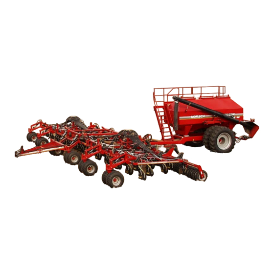
Configuration and Mode of Operation Description The Panther 440 and 460 Air Seeders, are typically used with a seed wagon after minimal cultivation. Triple Shoot Openers are used together with a fertilizer seed wagon. Here it is possible to apply the fertilizer accurately using an electronically controlled device, which enables it to be placed below the seed during sowing. - Page 35 The fertilizer is placed in the soil through a stainless steel pipe from behind the tip. The angled triangular baseplate divides and levels the seedbed over the liquid fertilizer. The fertilizer binds with the soil which is then covered and firmed. The Triple Shoot Opener wear plates open up the seed channel and the distributor deposits the seed over the required width.
- Page 36 NOTE: Replace any damaged or broken springs or other components immediately. For a complete list of serviceable items, see Panther Planting System Parts Catalog, or your nearest authorized HORSCH dealer. Picture to right indicates an assembled coulter unit with spring installed and pre-load set to the minimum setting, (8-3/4”).
-
Page 37: Transportation & Installation
Transportation & Installation Transportation The air seeder may only be towed when the cart hopper is empty. The maximum speed is 20 mph. • Hitch the air seeder to the tractor. • Connect the hydraulic system. • Fold the wings of the frame and secure. •... -
Page 38: Attaching The Air Seeder
Attaching the Air Seeder The air seeder can be hitched up to the rear of a cart/seed wagon or directly to the tractor. CAUTION! When hitching up the machine, ensure that nobody is between the tractor and the machine. NOTE: When close to the machine, avoid sharp edges which can cause injury. 1. -
Page 39: Connect The Road Lighting System
Folding: 1. Raise the air seeder to its up position. Install 4” cylinder stops on main frame, lower down on stops and inner wings. 2. Activate control lever and gradually fold the outer wings and inner wings. 3. Attach the folding safety bolts. Unfolding: 1. -
Page 40: Panther Lighting Harness
Panther Lighting Harness 40 | P a g e P a n t h e r S e r i e s O w n e r ’ s M a n u a l... -
Page 41: Panther Lighting Schematic
Panther Lighting Schematic P a n t h e r S e r i e s O w n e r ’ s M a n u a l 41 | P a g e... -
Page 42: Panther Lighting Wire Summary Chart
Panther Lighting Wire Summary Chart 42 | P a g e P a n t h e r S e r i e s O w n e r ’ s M a n u a l... -
Page 43: Technical Data
@ 60 PSI. (Optional) Trip Shank Force: …………………. 750 lbs. Trip Distance: ………………………. 11.5 in. Power Requirement: ………………. 400-500 HP (*) Panther 460 Working Width (ft.): ………………… 60 ft. Transport Width (ft.): ………………. 19 ft. Transport Height (ft.): ……………… 16 ft. -
Page 44: Wireless Flow Blockage Monitor System Wiring Diagrams
Wireless Flow Blockage Monitor System Wiring Diagrams Single Shoot Harness, Master ECU Single Shoot Harness, Right ECU 44 | P a g e P a n t h e r S e r i e s O w n e r ’ s M a n u a l... -
Page 45: Double Shoot Harness, Master Ecu
Double Shoot Harness, Master ECU Double Shoot Harness, Right ECU P a n t h e r S e r i e s O w n e r ’ s M a n u a l 45 | P a g e... -
Page 46: Parking The Air Seeder
Parking the Air Seeder The air seeder should be parked indoors or under cover whenever possible to prevent moisture collecting in the distributor, metering units, or seed tubes. The Panther air seeder can be parked separately or together with the seed wagon. This prevents the drawbar from tilting upwards when it is unhitched. -
Page 47: Adjustment/Operation
Adjustment/Operation Walking Tandem Packer Wheels The packers are made up of several flexing sections. The packer consolidates the soil and leaves a level and water permeable seedbed. In the transportation position the center packer acts as a chassis. The two outer packers are folded and the center pack supports the machine. - Page 48 Checking/Maintenance: The factory settings on the packer top links do not usually need to be adjusted. Check the tightness of all the top link counternuts (upper link) regularly. • Check the tightness of the wheels and flange bearings. • Check the tightness of the screw connections and setting spindles. •...
- Page 49 Panther 440/460 rear packer linkage and lift system P a n t h e r S e r i e s O w n e r ’ s M a n u a l 49 | P a g e...
-
Page 50: Manifold System
Manifold System The manifold heads provide the air and seed to the openers. Double shoot systems have four manifold heads, while single shoot only have two manifold heads. If a 24/12 manifold lid is used, it is important to distinguish between the hoses which are connected to the open outlets and those which are connected to the sealed outlets. - Page 51 Maintenance: The manifold heads must be checked for foreign material at regular intervals. Foreign material disturbs the seed flow product distribution, and the operation of the sensors. The hoses and manifold lid must be firmly attached and sealed. Any air leaks will result in uneven seed distribution and blocked seed hoses.
- Page 52 52 | P a g e P a n t h e r S e r i e s O w n e r ’ s M a n u a l...
- Page 53 Setup for Corn Planting: Using the AE-15 Double Shoot Opener with NH3 system, you can plant the corn in paired rows and put the NH3 below the seed in 30” rows. The seed corn best recommended for us is a medium round size seed.
-
Page 54: Planting Systems Settings On Corn
Planting Systems Settings on Corn • Seed Selection • Weights and Measures • Calibrating Machine • Drill Configuration • Agronomic Tips Seed Selection: When making your seed corn selection, the following considerations should be taken: • Seed Corn must be Medium Rounds. •... - Page 55 Machine Calibration: • Blue Meter Roller • Used for higher population rates • Red Meter Roller • Used for lower population rates Drill Configuration: • Remove top cover and dampener from stainless steel manifold. • Remove cover plate. • 30” Row Crop insert. P a n t h e r S e r i e s O w n e r ’...
- Page 56 • Inspect manifold head to check for any wear or damage. • Clean manifold area. • Make sure to line up timing marks insert manifold. • Once manifold is inspected and time marks identified, place insert in manifold head. • Use a Double Shoot paired row opener when planting corn.
- Page 57 • Use the Single Shoot, reverse drop for dry, liquid or anhydrous. • Use AE-SS Liquid or NH3 models if necessary. • Mid row fertilizer is a huge benefit in late season growth. • A Double Shoot system can be configured to apply in row and mid row bands of fertilizer.
-
Page 58: Agronomic Tips
The true measure of a planting system is the total bushels produced at harvest. With the HORSCH Panther 460 or 440 air seeder, you will give your crop the best possible start of any system. For more details on the features of these planting systems, contact your local HORSCH dealer. - Page 59 P a n t h e r S e r i e s O w n e r ’ s M a n u a l 59 | P a g e...
-
Page 60: Depth Setting
Depth Setting When in operation, the air seeder is supported by 12 hydraulic cylinders which raise the machine for sowing. The rear main cylinders divide the lift hydraulic system in to two separate circuits. In each circuit all the cylinders are arranged in series. The diameter of each following (series) cylinder is smaller to enable the lifting distance to remain constant across the entire working width. - Page 61 • Every step on the depth stop chart moves the air seeder approximately 0.31” or 5/16” either up or down. P a n t h e r S e r i e s O w n e r ’ s M a n u a l 61 | P a g e...
-
Page 62: Setting The Seeding Depth
Setting the Seeding Depth To adjust the depth, remove the same number and color combinations of spacers from all the depth guides. The ratio is approximately 2:1. Adjusting the connecting rod 1” alters the heights of the machine by approximately 2”. The various spacer combinations (see diagram on hydraulic cylinder) enable the height to be adjusted by approximately 0.31”... - Page 63 6. If working on a 60ft machine, repeat the step above one more time to level the machine. For comparison, review the difference in machine height between locations 1 and 5 for both sides and locations 2 and 6. After they have been adjusted, the height difference should be the same from one end of the machine to the other, front to back.
- Page 64 Clamping Adjusting Front Caster Towers Adjusting Plates (x4 – Panther 460, x2 – Panther 440) Adjusting Clamping Rear Packer Adjusting Plates (x6 – Panther 460, x4 – Panther 440) HINT: When making adjustments, to raise the machine adjust the bolt inward toward hydraulic cylinder;...
- Page 65 Panther Measuring Points Adjusting Points from Drawbar, Casters & Packers. Panther Adjusting Points from Drawbar, Casters & Packers. P a n t h e r S e r i e s O w n e r ’ s M a n u a l 65 | P a g e...
-
Page 66: Timing Of The Front Hitch
Panther 460 pictured above When examining the adjusting plates for damage or movement, look for a broken adjusting bolt or compressed threads between the locking jam nut and the head of the bolt. -
Page 67: Checking The Seed Depth Of The Machine
Checking the Seed Depth of the Machine Front to back – The red and blue lines pointing to the front and back openers of the air seeder are the ones that need to be checked to determine the levelness of the machine from front to back. (See picture on previous pages.) If it is determined that one is deeper than the other and you have found that the seed depth is incorrect, you will need to raise or lower the area of the machine where the opener is putting the... - Page 68 Determining Seed Depth 68 | P a g e P a n t h e r S e r i e s O w n e r ’ s M a n u a l...
-
Page 69: Machine Work Instructions
Machine Work Instructions Driving Speed: Seeder speed depends on the field conditions (type of soil, harvesting residues, etc.), the seed, the seed rate, the openers and other factors. Drive according to conditions. If it is difficult seeding, slow down. It is always best to go slower than go too fast when seeding. Checks: The seeding quality essentially depends on the adjustments and checks made prior to and during seeding, as well as on regular servicing and maintenance of the machine. -
Page 70: Rephasing The Hydraulic Cylinders
Rephasing the Hydraulic Cylinders The air seeder chassis is fitted with hydraulic rephasing cylinders. The cylinders are all connected in series and therefore operate up/down in parallel. Here, the hydraulic oil is forced out of the piston rod chamber of one cylinder in to the piston chamber of the next cylinder, and so on and so forth, for however many cylinders are connected in series (typically three). -
Page 71: Disc Leveler
Disc Leveler • The discs are arranged behind the shanks, slanting in the direction of travel, and prevents the soil, which is thrown up, from forming ridges at high speeds. Rear Drawbar • A drawbar can be mounted on the center packer in order to hitch the commodity cart. -
Page 72: Hydraulic Cylinders
Hydraulic Cylinders Troubleshooting: If several rephasing hydraulic cylinders are connected in series and one cylinder has an internal leak, it is only possible to locate the defective cylinder using a shut-off valve. A Shut-Off Valve (Cylinder Test Kit) is available for purchase from your local authorized dealer, PN 05945100. •... - Page 73 Hydraulic Schematic: Work Switch: P a n t h e r S e r i e s O w n e r ’ s M a n u a l 73 | P a g e...
- Page 74 Seed Sensor System: 74 | P a g e P a n t h e r S e r i e s O w n e r ’ s M a n u a l...
-
Page 75: Openers
Openers Different types of opener designs and variations have been developed for the various seeds and soil applications. The openers are available in several working widths and can be mounted on the shanks using adapters. For further information contact your local authorized dealer. Anderson Triple Shoot Opener The Triple Shoot Opener is a combined seeding and fertilizing opener. - Page 76 30” rows. * For a complete list of Openers available for different applications, please contact your local authorized HORSCH dealer. 76 | P a g e P a n t h e r S e r i e s O w n e r ’ s M a n u a l...
-
Page 77: Maintenance
Maintenance Maintenance and Service Follow the safety instructions for servicing and maintenance. Your air seeder has been designed and constructed for maximum performance, operational efficiency and operator friendliness under a wide variety of operating conditions. Prior to delivery, the machine has been inspected at the factory and the dealership to ensure that you receive an air seeder in optimum condition. - Page 78 Operator Support HORSCH wants you to be completely satisfied with your air seeder. Should you have any problems, please contact your dealer/distributor and Service Technician at any time. In order for us to process technical requests more quickly, we ask you provide specific information about the machine for a better understanding of the issue to better assist you in customer service.
- Page 79 Tightening Wheel Hardware Torque wheel hardware using the following procedure: IMPORTANT: Wheel bolts must be clean and oil free when torqueing. Torque values specified in the following steps are for clean, dry wheel bolts. Lubricating oil reduces friction and thread bite to overload bolts. Initial Wheel Bolt Torque Use the tightening sequence shown in the picture attached.
- Page 80 The recommended service intervals are based on normal conditions; severe or unusual conditions may require more frequent lubrication. Perform each lubrication and service procedure illustrated in this section at the beginning of each season. Clean grease fittings before using grease gun. Replace any lost or broken fittings immediately. If a new fitting fails to take grease, remove and check for failure of adjoining parts.
- Page 81 Walking Tandem Adjustment Walking tandems should occasionally be adjusted by using the wrenches supplied, located on the front hitch of the machine. Loosen jam nut A and tighten jam nut B until there is a slight drag applied to the tandem. Then retighten the jam nut A to jam nut B.
-
Page 82: Hitch Adjustment & Maintenance
Hitch Adjustment & Maintenance The front hitch of a seed wagon has a few options for hitching to the rear hitch of a planting system. There are typical Thru-Hole Drop Pin type hitches, and Ball Head type hitches. The Thru-Hole type will not require any adjustment or maintenance, except height location desired based on planting system. - Page 83 1. Remove the circlips and pins (A) of the hold-down securing it to the casting. 2. Remove the hold-down assembly (B) from the ball carrier casting. 3. By turning the adjusting screw (C) adjust the height of the hold-down as necessary. 4.
-
Page 84: Maintenance Schedule
Maintenance Schedule After First Operation Instructions Interval Check all hardware Tighten if necessary Lubricate Air Seeder See Overview of Lubricating Points Before Each Operation Instructions Interval Lubricate Air Seeder See Overview of Lubricating Points Raise Seeder to top position several tim es Balance hydraulic cylinders (height adjustm ent) daily Upper Links Tighten if necessary... -
Page 85: Overview Of Lubricating Points
Wing pivot pins (Inner & Outer) (x8 – Panther 460, x4 – Panther 440) P a n t h e r S e r i e s O w n e r ’ s M a n u a l... - Page 86 Caster Axle (x1 per axle) Spindle Hub (x1 per axle – Caster & Packer) Parallel Caster Pivot Arms Caster Tower (x1 per Caster) Front Drawbar (x4 per side) 86 | P a g e P a n t h e r S e r i e s O w n e r ’ s M a n u a l...
- Page 87 Rear Drawbar Pins (x2) Packer system pivot pins (x1 per packer) Cutting Coulter Disc & Shank (x1 each) P a n t h e r S e r i e s O w n e r ’ s M a n u a l 87 | P a g e...
- Page 88 Lubricating the Machine Please read the section below entitled ‘Handling of Lubricants’ carefully before lubricating the machine. The machine must be greased regularly in order for it to remain serviceable. Regular greasing also contributes towards extending the service life of the machine. The recommended service intervals are specified above.
-
Page 89: Troubleshooting
The following charts are intended to enable you to quickly remedy any malfunctions. If you’re unable to find a particular malfunction in the charts, contact your nearest authorized HORSCH dealer for further assistance and customer service. -
Page 90: Service & Information
Service & Information Metric Bolt & Screw Torque Values Bolt tightening Torques - Metric bolts (Ft. Lbs) Bolt Diameter Grade 4.8 Grade 5.8 Grade 8.8 Grade 10.9 Grade 12.9 Wheel Nuts/ Bolts Size Pitch Dry Lubed Dry Lubed Dry Lubed Dry Lubed Dry Lubed 0.50 0.70 0.80... -
Page 91: Imperial/Standard Bolt & Screw Torque Values
Imperial/Standard Bolt & Screw Torque Values Bolt tightening Torques - Imperial bolts (Ft. Lbs) Bolt Diameter SAE Grade 2 SAE Grade 5 SAE Grade 8 Size Thread Lubed Lubed Lubed Lubed 5/16 5/16 7/16 7/16 9/16 9/16 1000 1 1/8 1280 1150 1 1/8... -
Page 92: Metric Conversions
Shear bolts are designed to fail under predetermined loads. Always replace a shear bolt with identical property class. Fasteners should be replaced with the same or higher property class. If higher property class fasteners are used, these should only be tightened to the strength of the original. Make sure fastener threads are clean and that you properly start thread engagement. -
Page 93: Hydraulic Schematic - Lift (Panther 460 Shown)
Hydraulic Schematic – Lift (Panther 460 shown) Item 32 is a filter screen used to prevent foreign material from entering the hydraulic system of the air seeder. If the air seeder starts to raise and lower at a slower rate than normal rate, this screen could be plugged and should be removed and cleaned thoroughly. -
Page 94: Hydraulic Schematic - Fold (Panther 460 Shown)
Hydraulic Schematic – Fold (Panther 460 shown) 94 | P a g e P a n t h e r S e r i e s O w n e r ’ s M a n u a l... - Page 95 Cylinder Rod Maintenance PRP (Piston Rod Protection) Chrome plated piston rod and bar products normally contain a minimum of 20 microns to 50 microns hard chrome plate, depending upon the product specifications. This hard chrome plating is applied primarily for wear resistance, though it does considerable corrosion resistance as well. Once the shaft is assembled into a cylinder and put into service, the hydraulic fluid on the surface provides additional corrosion resistance that is normally sufficient to protect the shaft during its entire life.
- Page 96 Protect Your Hydraulic Cylinders from Rust Many types of equipment have hydraulic cylinders. A hydraulic cylinder is a piston that slides within a cylindrical body. A rod attached to the piston passes through a seal at the end of the cylindrical body and moves in and out to do useful work.
-
Page 97: Notes
Notes: Go to Top P a n t h e r S e r i e s O w n e r ’ s M a n u a l 97 | P a g e... - Page 98 HORSCH, LLC 200 Knutson St. Mapleton, ND 58059 Telephone: (701) 532-1000 Fax: (701) 532-1101 Toll Free: 855-4HORSCH Email: info.us@horsch.com Web: www.horsch.com PN 04119210...
Need help?
Do you have a question about the Panther 460 and is the answer not in the manual?
Questions and answers