Table of Contents
Advertisement
Advertisement
Table of Contents

Related Manuals for IFM E30391


Summary of Contents for IFM E30391
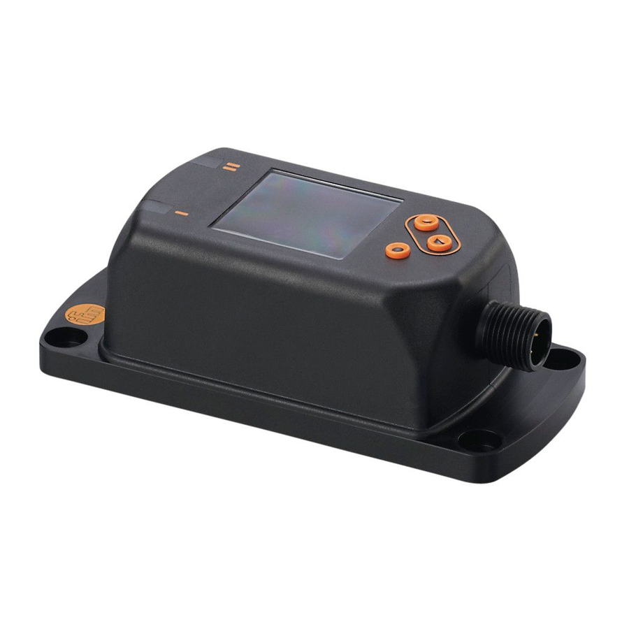
- Page 1 Programming instructions IO-Link Display 1,44” E30391...
-
Page 2: Table Of Contents
Content 1. Installation and electrical connection ..........3 2. Set-up..................... 3 3. Parameter setting (acyclic communication) ........5 3.1. Parameter setting with LINERECORDER DEVICE .... 6 3.2. Process value display ............7 3.3. Text content for info pages ..........7 3.4. -
Page 3: Installation And Electrical Connection
When the IO-Link Display is connected to an IO-Link master the IO-Link port has to be configured. In this example the IO-Link master AL1000 from ifm electronic is used with the Siemens software Step 7. The IO-Link Display has an interface with 1-byte input (→ 4.2 Input... - Page 4 If there is no explicit module on the master used it is possible to use an existing module with a wider interface. Drag, for example, a 24/24-byte I/O module to the master port to which the IO-Link Display is to be connected. Double click on the module: Enter name and comment as an option: Enter addresses for input and output ranges:...
-
Page 5: Parameter Setting (Acyclic Communication)
Enter vendor ID and device ID to ensure that only an IO-Link Display 1,44” can be operated at that port. Set the data storage according to the application's requirements: Write the configuration to the controller or PLC. Connect the IO-Link Display to the master using a 3-wire cable. Parameter setting (acyclic communication) Settings can be made and predefined text can be entered by means of the IO-Link parameter setting tool or a PLC by writing... -
Page 6: Parameter Setting With Linerecorder Device
3.1. Parameter setting with LINERECORDER DEVICE ► Connect the IO-Link Display via the USB interface E30390. ► Start the LINERECORDER DEVICE. ► Read parameters from the IO-Link Display: ► Change parameters. ► Write parameters to the IO-Link Display: > The IO-Link Display can now be connected to the IO-Link master. -
Page 7: Process Value Display
3.2. Process value display Type / Name Index / Content length subinde Unit 1 80/0 Unit 2 81/0 Units of the process String/8 values Unit 3 82/0 Unit 4 83/0 Description 1 90/0 Description 2 91/0 Description text of String/16 the process values Description 3 92/0... - Page 8 Type / Name Index / Content length subindex Info page 3, line 1 130/0 Info page 3, line 2 131/0 Info page 3, line 3 132/0 String/16 Text content of page 3 Info page 3, line 4 133/0 Info page 3, line 5 134/0 Info page 4, line 1 135/0...
-
Page 9: Background Colour Of The Info
Name Index / Type Content subind lengt Info page 9, line 1 12120/0 Info page 9, line 2 12121/0 Info page 9, line 3 12122/0 String/16 Text content of page 9 Info page 9, line 4 12123/0 Info page 9, line 5 12124/0 Info page 10, line 1 12125/0... - Page 10 Type / Name Index / Content length subindex Text 1 161/0 Text 2 162/0 Text 3 163/0 Text 4 164/0 Text 5 165/0 Text 6 166/0 Text 7 167/0 Text 8 168/0 Text 9 169/0 Text 10 170/0 Text 11 171/0 Text 12 172/0...
-
Page 11: Predefined Text Instead Of Process Values
3.6. Predefined text instead of process values Text defined in the device which can be used instead of process values. Index / Type / Text subindex length 1000/0 String/16 1001/0 String/16 °C 1002/0 String/16 °F 1004/0 String/16 1005/0 String/16 ° 1010/0 String/16 1012/0... - Page 12 Index / Type / Text subindex length 1133/0 String/16 1136/0 String/16 1137/0 String/16 1138/0 String/16 mbar 1141/0 String/16 1146/0 String/16 inH2O 1149/0 String/16 mmH2O 1155/0 String/16 inHg 1157/0 String/16 mmHg 1211/0 String/16 1212/0 String/16 µA 1240/0 String/16 1243/0 String/16 1342/0 String/16 1348/0 String/16...
-
Page 13: Display Configuration
3.7. Display configuration Definition of rotation, brightness and colour scheme of the display. Index / Type / Name Content subindex length diS.R 801/0 Rotation of the display Setting values: 0°, 90°, 180°, 270° Brightness of the display: diS.B 802/0 UINT8/1 0 %, 25 %, 50 %, 75 %, 100 % diS.S 803/0... -
Page 14: Io-Link Process Data (Cyclic Communication)
IO-Link process data (cyclic communication) 4.1. Output data The connected PLC transmits process values in the output data stream and controls the display of the process values. It is defined in the layout byte which layout is to be displayed, e.g. 1 large process value or an info page. - Page 15 Type / Name Byte Note / length offset content Colour and flashing (frequency 2 Hz) Color1: Display line 1 Colour of the static Color2: Display process value: 0 = black-white line 2 1 = red Color3: Display 10.0 2 = green line 3 3 = yellow Color1: Display...
-
Page 16: Input Data
Type / Name Byte Note / length offset content Display layout 13.0 INT8/1 0 = Start screen 1 = layout 1 for one process value 2 = layout 2 for two process values 3 = layout 3 for three process values 4 = layout 4 for four process values 11 = display info page 1 12 = Display info page 2... -
Page 17: Examples
Address / bit Function Description Reserved Reserved Content inv The device found out that at least one of the received output data (→ 9.1 Output data) is inconsistent. The device confirms that the received PDout inv output data (→ 9.1 Output data) had already been marked as invalid by the transmitter. -
Page 18: Example 2: Display Two Process Values
4.3.2. Example 2: display two process values Define unit, description text and number of decimal places (index 80, 90 and 100 → 3.2) In the output data stream, set the layout to 2 (byte 13 → 4.1). As an option define the text colours (byte 8 → 4.1). Write both display values as Integer16, starting at byte 0 in the output data (→... -
Page 19: Example 3: Display Text Instead Of Process Values
4.3.3. Example 3: display text instead of process values Define text for a certain text ID (index 160 to 174 → 3.5; 0). Use this text ID for the requested process value by setting text red or text black and white. At the same time this defines a text colour (bytes 8 to 11 →... -
Page 20: 4.3.5. Example 5: Display Qr-Code
In order to display the QR-Code on the display set the layout to 21 during run time (Byte 13 → 4.1). Technical data Technical data and scale drawing at www.ifm.com. 5.1. Identification parameters These parameters contain the identification data of the IO-Link device.
Need help?
Do you have a question about the E30391 and is the answer not in the manual?
Questions and answers