
Subscribe to Our Youtube Channel
Related Manuals for Pixsys DRR244


Summary of Contents for Pixsys DRR244
- Page 1 DRR244 Controller / Regolatore / régulateur User manual / Manuale d’uso / Manuel utilisateur...
-
Page 2: Safety Guidelines
Introduction The process controller DRR244 is specifically conceived for application on control panels with DIN rail mounting. It stands out for the bright display which ensures optimal visibility and increased level of information for the operator beside a scrolling help function. -
Page 3: Precautions For Safe Use
According to European Directive 2002/96EC on waste electrical and electronic equipment and its implementation in accordance with national law, electric tools that have reached the end of their life must be collected separately and returned to an environmentally compatible recycling facility. User manual - DRR244 - 7... -
Page 4: Model Identification
Model Identification The DRR244 controller provides the following model: Power supply 24..230 VAC/VDC ±15% 50/60 Hz – 9 Watt/VA 1 analogue input + 2 relays 5 A + 1 relay 2 A + 2 SSR + 2 D.I. + 1 analogue output... -
Page 5: Programming Mode
When activated by a reader/interrogator supporting NFC-V protocol, App MyPixsys controller DRR244 is to be considered a VICC (Vicinity Inductively Coupled Card) according to ISO/IEC 15693 and it operates at a frequency of 13.56 MHz. The device does not intentionally emit radio waves. -
Page 6: Wiring Diagram
• When shielded cable is used, it should be grounded at one side only to avoid ground loop currents. AI1 V mA • It’s possible to select +V at 12Vdc or 24Vdc, by configuring parameter 282 (GROUP R - - Display and interface). V.out diSP. Shield/Schermo 10 - DRR244 - User manual... - Page 7 Electrical endurance Q1, Q2: DC30 V t=7ms • 5A, 250 VAC, resistive loads, 10 operations. • 20/2A, 250 VAC, cosφ = 0.3, 10 operations. AC250V COS ø=0.4 DC30 V t=15ms Contact load current (A) User manual - DRR244 - 11...
-
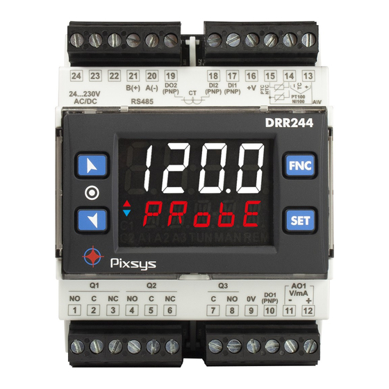
Page 8: Display And Key Functions
ON when alarm 3 is active. ON when the controller is executing an auto-tuning cycle. ON when “Manual” function is active. ON when the controller communicates through serial. Flashes when the remote setpoint is enabled. 12 - DRR244 - User manual...
Need help?
Do you have a question about the DRR244 and is the answer not in the manual?
Questions and answers