Table of Contents
Advertisement
Available languages
Available languages
Quick Links
Advertisement
Table of Contents

Related Manuals for Pixsys DRR460


Summary of Contents for Pixsys DRR460
- Page 1 DRR460 CAN Controller / Regolatore User manual - Manuale uso...
-
Page 3: Table Of Contents
Table of contents Safety guidelines ................................8 Organization of safety notices ........................8 1.2 Safety Precautions ............................. 8 1.3 Precautions for safe use ........................... 9 Environmental policy / WEEE .......................... 9 Model identification ..............................10 Technical data................................10 Main features ..............................10 3.2 Hardware Features ............................ - Page 4 11.1.1 CANopen communication model ....................23 11.1.2 CANopen Pre-defined Connection Set ................... 24 11.1.3 CANopen identifier distribution .......................25 11.1.4 CANopen boot-up process ........................25 11.1.5 Communication profile: start ......................26 11.2 Communication Profile Area ........................27 11.2.1 Device Type ............................27 11.2.2 Error Register............................28 11.2.3 Pre-defined Error Field ........................28 11.2.4...
- Page 5 11.4.11 Analogue Input Interrupt Negative Delta Unsigned ..............51 11.4.12 Analogue Input Interrupt Positive Delta Unsigned ..............51 11.4.13 Analogue Output Error Mode ......................51 11.4.14 Analogue Output Error Value Integer ..................... 51 11.4.15 Error Behaviour ............................ 51 11.5 PDO Transmission............................52 11.5.1 PDO Mapping ............................
- Page 6 9.a Allarme assoluto o allarme di soglia attivo sopra (Index 0x3000 Sub-Index 56 = 1) ......70 9.b Allarme assoluto o allarme di soglia riferito al setpoint di comando attivo sopra (Index 0x3000 Sub-Index 56 = 6) ..............................70 9.c Allarme di Banda (Index 0x3000 Sub-Index 56 = 3) ..................70 9.d Allarme di deviazione superiore (Index 0x3000 Sub-Index 56 = 4) ............
- Page 7 11.3.18 Comando automatico / manuale ....................100 11.4 Standard Device Profile Area ........................100 11.4.1 Digital Output ............................101 11.4.2 Error Mode Output 8bit ........................101 11.4.3 Error Value Output 8bit ........................101 11.4.4 Analogue Input 16bit ........................101 11.4.5 Analogue Output 16bit ........................102 11.4.6 Analogue Input Interrupt Trigger Selection ................102 11.4.7 Analogue Input Global Interrupt Enable ..................102 11.4.8...
-
Page 8: Safety Guidelines
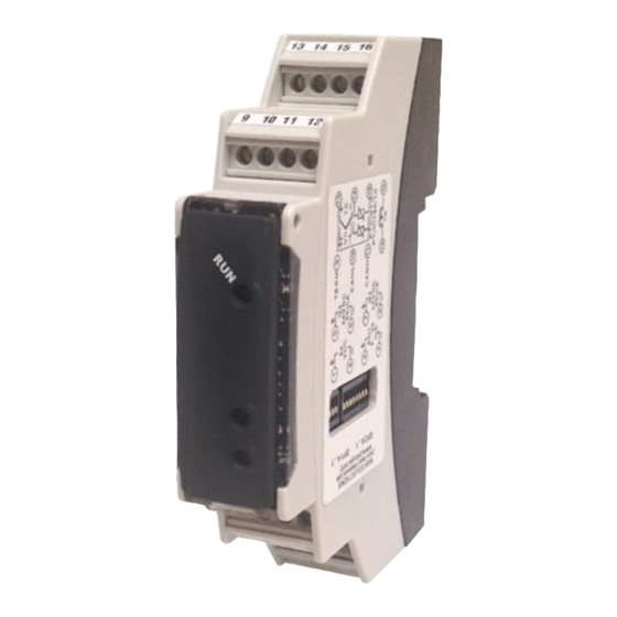
Thanks for choosing a Pixsys controller. The DRR460 series integrates in a single device the main elements of the control loop: reading of temperature sensor, control output by SSR module, reading and control of the current on the load by means of integrated current CT. -
Page 9: Precautions For Safe Use
According to European Directive 2012/19/EU on waste electrical and electronic equipment and its implementation in accordance with national law, electric tools that have reached the end of their life must be collected separately and returned to an environmentally compatible recycling facility. User manual - DRR460 CAN - 9... -
Page 10: Model Identification
P, PI, PID, PD proportional time. Proportional band 0..999°C or °F Integral time 0,0..999,9 s (0 excludes integral function) Derivative time 0,0..999,9 s (0 excludes derivative function) Controller functions Manual or automatic tuning, configurable alarm, Start/Stop. 10 - DRR460 CAN - User manual... -
Page 11: Dimensions And Installation
• Wiring of pins use crimped tube terminals or flexible/rigid copper wire with diameter 0.25 to 1.5 mm2 (min. AWG28, max. AWG16, operating temperature: min. 70°C). Cable stripping lenght 7 to 8 Wiring diagram DRR460-12A-CAN Power Supply 5.1.a 24 VDC Power supply 24 VDC ±15% – User manual - DRR460 CAN - 11... -
Page 12: Analogue Input
B= Sensor ground For linear signals 0/4..20 mA with two-wires sensors. Comply with polarity: 4...20mA A= Sensor output C= Sensor supply (24VDC) PRESSURE TRANSMITTER / SENSORE DI PRESSIONE Short circuit pins 2 and 14. 12 - DRR460 CAN - User manual... -
Page 13: Serial Input
Heater Break Alarm control. • If pressed during the modbus address assignment function, it stores the value assigned by the master (only if the dip1 is all in OFF). User manual - DRR460 CAN - 13... -
Page 14: Dip Switch
(at least 30%). AutoTuning Launch “Once” Set 3 on Index 0x3000, Sub-Index 31. Autotuning procedure is executed only once at next DRR460 restart. If the procedure doesn’t work, will be executed at next restart. -
Page 15: Synchronized Tuning
(Index aL. 1. aL. 2. 0x3000 Sub-Index 56 or sub-Index 68). It is possible also to enable an overcurrent control, setting on parameter (Index 0x3000 Sub-Index ocu.t. 93) the intervention threshold in Ampere. User manual - DRR460 CAN - 15... -
Page 16: Dual Action Heating-Cooling
Dual Action Heating-Cooling DRR460 is suitable also for systems requiring a combined heating-cooling action.The command output has to be configured as PID for Heating (par. - Index 0x3000 Sub-Index 33 -greater than 0), p.b. while the alarm 1 and 2 has to be configured as Cooling (value 9 on par. -
Page 17: Soft-Start Function
Soft-Start function DRR460 is provided with two types of softstart selectables on parameter 80 (“Softstart Type” Index SS.tY. 0x3000 Sub-Index 80). 1 First selection (value 1 of Index 0x3000 Sub-Index 80) enables gradient softstart. At starting the controller reaches setpoint basing on the rising gradient set on parameter (“Softstart Gradient”... -
Page 18: Regulation Control
7.12 Regulation control DRR460 integrates diff erent types of control for the regulation of the command output, selecting parameter 52 (“Output Control Type” index 0x3000, sub-index 52) as follows: o.cL.t. 0 Time control 7.12.a For this type of control it is necessary to use a “zero-crossing” SSR. -
Page 19: Expansion Function
0x3000 Sub-Index 122 - 131 (see par. 9). Serial communication DRR460-12A-CAN is equipped with an USB micro connector which, connected to the PC, allows the communication with the Pixsys confi guration program LabSoftView (available on the reserved area of www.pixsys.net). -
Page 20: Upper Deviation Alarm (Index 0X3000 Sub-Index 56 = 4)
“0” (Par. Index 0x3000 Sub-Index 58 > 0). a. 1 .HY With hysteresis value less than “0” ( < 0) the dotted line moves A. 1 .HY. Time under the alarm setpoint. Alarm output 20 - DRR460 CAN - User manual... -
Page 21: Canopen
Stopped status from Pre-Operational or Operational status by rounding rotary switch in position 0. Replacing switch in other positions, device will change into Pre-Operational status anyway. 10.3 EDS Files EDS files of the different models are available on the download area of www.pixsys.net. User manual - DRR460 CAN - 21... -
Page 22: Canopen In Details
Each entry into the dictionary is identified by a 16 bit index which indicates the row address of the table. A maximum of 65536 entries are permitted. If an object is composed of several components, the components are identified by means of an 8 bit 22 - DRR460 CAN - User manual... -
Page 23: Canopen Communication Model
PDO Communication Parameter and it’s defined as an unsigned 16bit integer (unit is 100µsec). • Event time period for a PDO defines where PDO transmission is periodically triggered when a User manual - DRR460 CAN - 23... -
Page 24: Canopen Pre-Defined Connection Set
0011 0x181 – 0x1FF 0x1800 PDO1 (receive) 0100 0x201 – 0x27F 0x1400 PDO2 (transmit) 0101 0x281 – 0x2FF 0x1801 PDO2 (receive) 0110 0x301 – 0x37F 0x1401 PDO3 (transmit) 0111 0x381 – 0x3FF 0x1802 24 - DRR460 CAN - User manual... -
Page 25: Canopen Identifier Distribution
COB-ID allocation are possible by SDO only. A distinction is needed between device configuration and CANopen device initialisation (boot-up). DRR460-CAN configuration is allowed when device is powered-on with rotary switch in position 0 (Node-ID offset multiplier, baud-rate); DRR460-CAN CANopen initialisation (boot-up) is always provided by itself when it is powered-on (for each position of rotary switch). -
Page 26: Communication Profile: Start
3.Tx PDO: contains the following values Index Sub - index Description Default value 0x1A02 Number of objects 1...8 4.Tx PDO: contains the following values Index Sub - index Description Default value 0x1A03 Number of objects 1...8 26 - DRR460 CAN - User manual... -
Page 27: Communication Profile Area
If at least one analogue input is connected If no analogue output is connected If at least one analogue output is connected For DRR460 the value is 0x000E0191 Least significant word (LSW) is always 0x0191 = 401 CAN DS standard. User manual - DRR460 CAN - 27... -
Page 28: Error Register
11.2.5 Communication Cycle Period This object contains maximum time (msec) between 2 SYNC messages (resolution 2msec). If value is 0, no SYNC monitoring is realized. Index Subindex Name Type Default Communication Cycle 0x1006 32bit unsigned Period 28 - DRR460 CAN - User manual... -
Page 29: Manufacturer Device Name
This object allows to reset user stored parameters and load default values. If signature “load” (ASCII 0x64616F6C) is written on Sub-index 1, standard default parameters are loaded each power on (until next “save” command is written). Index Subindex Name Type Default 0x1011 Number of sub-index Array 8bit unsigned User manual - DRR460 CAN - 29... -
Page 30: Cob-Id Emergency Object
0x1029 Number of Sub-index Array 8bit unsigned Communication error Array 8bit unsigned Structure: Communication error Action Change into status PRE-OPERATIONAL (only if actual status were OPERATIONAL) No status change Change into status STOPPED 30 - DRR460 CAN - User manual... -
Page 31: Receive Pdo Communication Parameter
SYNC as 1...240 i SYNC (i = requested 1...240) by last PDO received 241..251 Reserved Data is read again with a SYNC, but not sent, supported request via Request via User manual - DRR460 CAN - 31... -
Page 32: Receive Pdo Mapping Parameter
Record 16bit Inhibit Time unsigned Record 16bit Event Timer unsigned COB-ID Structure: Bit 31 Bit 30 Bit 29...11 Bit 0...10 0(RTR allowed) / 1(RTR 0(valid) / 1(invalid) 0 Reserved COB-ID not allowed) 32 - DRR460 CAN - User manual... -
Page 33: Transmit Pdo Mapping
Subindex: object subindex to be transmitted Object size: object size in bits (no more than 8 bytes can be transmitted in a PDO, so sum of valid object lengths have not to exceed 64. User manual - DRR460 CAN - 33... -
Page 34: Manufacturer Specific Parameter Area
11.3 Manufacturer Specific Parameter Area The following table shows all Pixsys specific parameters objects supported: Index Name Type 0x2000 Device specifications Array 16bit signed R/W 0x3000 DRR460 Parameters Array 16bit signed R/W 0x4000 Command setpoint 16bit signed 0x4001 Alarm 1 setpoint... - Page 35 11.3.2 Table of configuration parameters The object index 0x3000 defines all DRR460 configuration parameters. The sub-index (1..143) identifies each parameter described below: Index Subindex Name Type Default 0x3000 Number of Sub-index Array 16bit signed 1..143 DRR460 parameters Array 16bit signed...
- Page 36 Stored. Backs the controller to the Start/Stop status existing before the switching-off. Action type (idx 0x3000, s-idx 18) Act.t. Heating (N.O.) (Default) Cooling (N.C.) Command Hysteresis (idx 0x3000, s-idx 19) c. HY. Hysteresis in ON/OFF -10000..+10000 [digit] (degrees.tenths for temperature sensors). Default 2. 36 - DRR460 CAN - User manual...
- Page 37 Valve time. 1...300 seconds. Default: 60. Automatic / Manual (idx 0x3000, s-idx 25) au.ma. Enable automatic / manual selection. Disabled (Default) Enabled Enabled with memory 26÷30 Reserved (idx 0x3000, s-idx 26..30) Reserved parameters User manual - DRR460 CAN - 37...
- Page 38 Selects command setpoint deviation to calculate the intervention threshold of “Off Over Setpoint” function. -10000...+10000 [digit] (degrees.tenths for temperature sensors) (Default: 0) Cycle Time (idx 0x3000, s-idx 40) c.t. Cycle time (for PID on teleruptor 15s ; for PID on SSR 2s.) 1-300 seconds (Default:15s) 38 - DRR460 CAN - User manual...
- Page 39 Disab. Lev . 4 Lev . 8 Def. Lev . 1 Lev . 9 Lev . 5 ( Lev . 2 Lev . 10 Lev . 6 Lev . 3 Lev . 7 User manual - DRR460 CAN - 39...
- Page 40 20 mA if alarm 1 on AO. Open contact if alarm 1 on Q1 or Q2 21.5 mA if alarm 1 on AO. Closed contact if alarm 1 on Q1 or Q2. Active alarm in Stop 40 - DRR460 CAN - User manual...
- Page 41 4 mA if alarm 1 on AO. Closed contact if alarm 1 on Q1 or Q2. 20 mA if alarm 1 on AO. Open contact if alarm 1 on Q1 or Q2 21.5 mA if alarm 1 on AO. Closed contact if alarm 1 on Q1 or Q2. User manual - DRR460 CAN - 41...
- Page 42 Max. softstart duration: if the process doesn’t reach the threshold entered on parameter 50 within the selected time, the controller will start to regulate on setpoint value. Disabled minutes. (Default: 15 minutes) 1...1440 85÷89 Reserved (idx 0x3000, s-idx 85..89) Reserved parameters 42 - DRR460 CAN - User manual...
- Page 43 -32767..+32767 [digit] (degrees for temperature sensors), Default: 0. 103 up.L.r. Upper Limit Retransmission (idx 0x3000, s-idx 103) Linear output upper limit range (value related to 20 mA) -32767..+32767 [digit] (degrees for temperature sensors), Default: 10000. User manual - DRR460 CAN - 43...
- Page 44 Selects the off-line time. If no communication is available within the selected time, the controller will switch-off the command output. Offline disabled (Default) tenths of seconds (Es. 100 = 10.0 s) 1...6000 116÷120 Reserved (idx 0x3000, s-idx 116..120) Reserved parameters 44 - DRR460 CAN - User manual...
- Page 45 Defines the value assumed by the output in case of error or off-line -32767..+32767 [digit] Default: 0. 131 C.t.ou. Current Transformer Output (idx 0x3000, s-idx 131) Defines digital output connected to the current transfomer Q1 (Default) 132÷136 Reserved (idx 0x3000, s-idx 132..136) Reserved parameters User manual - DRR460 CAN - 45...
-
Page 46: Command Setpoint
Cold junction temperature (idx 0x4006, s-idx 0) 16bit signed Defines the cold junction temperature. (degree.tenths) 11.3.10 Error Flags Error Flags (idx 0x4007, s-idx 0) 32bit unsigned Defines the flags for the DRR460 errors signalisation. Cold junction error bit 0 Process error (sensor) bit 1... -
Page 47: Real Command Setpoint
Defines the autotuning status and depends on the setting of Index 0x3000 Sub-Index 5. Auto tuning (idx 0x400E, s-idx 0) 8bit unsigned RO If Index 0x3000 Sub-Index 5 = 1 Autotuning OFF Autotuning ON User manual - DRR460 CAN - 47... -
Page 48: Automatic/Manual Command
Automatic/Manual command (idx 0x400F, s-idx 0) 8bit unsigned Defines the command status in automatic or manual. Automatic Manual 11.4 Standard Device Profile Area The table below indicates all supported Pixsys parameters: Index Name Type 0x6200 Digital Output Array 8bit unsigned... -
Page 49: Error Value Output 8Bit
Change of input value exceeding delta value for last transmission 0x6426 Reduction of input value by more than delta value for last transmission 0x6427 Increase of input value by more than delta value for last transmission 0x6428 5..7 Reserved User manual - DRR460 CAN - 49... -
Page 50: Analogue Input Global Interrupt Enable
Array 8bit unsigned inputs Delta 1st input Array 16bit unsigned Delta 2nd input Array 16bit unsigned Delta 3rd input Array 16bit unsigned Delta 4th input Array 16bit unsigned Delta 5th input Array 16bit unsigned 50 - DRR460 CAN - User manual... -
Page 51: Analogue Input Interrupt Negative Delta Unsigned
1st output Error Value Array 16bit signed 11.4.15 Error Behaviour This object has the same functionality of Error Behaviour 0x1029. Index Subindex Name Type Default 0x67FE Number of Sub-index Array 8bit unsigned Communication error Array 8bit unsigned User manual - DRR460 CAN - 51... -
Page 52: Pdo Transmission
As soon as Node Guarding is restored, another emergency message is sent (Error Code:0x0000, Error Register: 0x11, Additional Code 00 04 00 00 00), and device status doesn’t change. N.B. It’s only possible to use Node Guarding protocol or Heartbeat protocol, not both. 52 - DRR460 CAN - User manual... -
Page 53: Heartbeat Monitoring
00 04 00 00 00 greater than Guard Time x Life Time Factor Time between two Heartbeat telegrams is greater 0x8130 0x11 00 05 DD 00 00 than configured one DD: node has tripped time overflow User manual - DRR460 CAN - 53... - Page 54 1. For details on CANopen, see Chapter 11. 2. On activation, the output is inhibited if the controller is in alarm mode. Activates only if alarm condition reappers, after that it was restored. 54 - DRR460 CAN - User manual...
- Page 55 Minimum Integral Time (idx 0x3000, s-idx 50) mn. i .t. Overshoot Control Level 1 (idx 0x3000, s-idx 51) o.c.L. 1 Output Control Type (idx 0x3000, s-idx 52) o.cL.t. 53÷55 Reserved (idx 0x3000, s-idx 53..55) User manual - DRR460 CAN - 55...
- Page 56 Serial Port Parameters (idx 0x3000, s-idx 113) s.p.p. Serial Delay (idx 0x3000, s-idx 114) se.de. Off Line (idx 0x3000, s-idx 115) off.L. 116÷120 Reserved (idx 0x3000, s-idx 116..120) GROUP J - EXPANSION Expansion Module (idx 0x3000, s-idx 121) E.Mod. 56 - DRR460 CAN - User manual...
- Page 57 Error Mode Analogue Output (idx 0x3000, s-idx 129) E.M.A.o. Error Value Analogue Output (idx 0x3000, s-idx 130) E.v.A.o. Current Transformer Output (idx 0x3000, s-idx 131) C.t.ou. 132÷136 Reserved (idx 0x3000, s-idx 132..136) User manual - DRR460 CAN - 57...
-
Page 58: Norme Di Sicurezza
RS485 con protocollo Modbus Rtu o CANopen, consente la connessione a PC/terminali HMI per la supervisione ed il controllo a distanza. Completano il dispositivo le funzioni di allarmi, la gestione di impianti a doppia azione e la possibilità di usare il DRR460 come semplice espansione gestita da PLC. -
Page 59: Precauzioni Per L'uso Sicuro
WEEE Non smaltire le apparecchiature elettriche ed elettroniche tra i rifiuti domestici. Secondo al Direttiva Europea 2012/19/EU le apparecchiature esauste devono essere raccolte separatamente al fine di essere reimpiegate o riciclate in modo eco-compatibile. Manuale d’uso - DRR460 CAN- 59... -
Page 60: Identificazione Del Modello
P, PI, PID, PD a tempo proporzionale Banda proporzionale 0..999°C o °F Tempo integrale 0,0..999,9 s (0 esclude) Tempo derivativo 0,0..999,9 s (0 esclude) Funzioni del Tuning manuale o automatico, allarme selezionabile, Start/Stop. regolatore 60 - DRR460 CAN - Manuale d’uso... -
Page 61: Dimensioni Ed Installazione
0.25 e 1.5 mm2 (min. AWG28, max. AWG16, temperatura operativa: min. 70°C). La lunghezza di spelatura è compresa tra 7 e 8 mm. Schema di collegamento DRR460-12A-CAN Alimentazione 5.1.a 24 VDC Alimentazione 24 VDC ±15% – Manuale d’uso - DRR460 CAN- 61... -
Page 62: Ingresso Analogico
Per segnali normalizzati in corrente 0/4..20 mA con sensore a due fi li. Rispettare le polarità: 4...20mA A= Uscita sensore C= Alimentazione sensore (24VDC) PRESSURE TRANSMITTER / SENSORE DI PRESSIONE Cortocircuitare morsetti 2 e 14. 62 - DRR460 CAN - Manuale d’uso... -
Page 63: Ingresso Seriale
0.5s se l’operazione è andata a buon fine, mentre lampeggia in alternanza con il led OUT 1 se l’operazione non è andata a buon fine. • Lampeggia in alternanza con il led OUT 2 in caso di errore (es. rottura sonda). Manuale d’uso - DRR460 CAN- 63... -
Page 64: Tasto
Impostare 1 sull’ Index 0x3000 Sub-Index 31. Il tuning automatico è sempre attivo e analizza costantemente la differenza setpoint-processo. Se tale differenza è maggiore del valore impostato sull’ Index 0x3000 Sub-Index 47 (Max Gap Tune), il DRR460 decide autonomamente come modificare i parametri PID. 64 - DRR460 CAN - Manuale d’uso... -
Page 65: Lancio Dell'autotuning "Manuale
Lancio dell’AutoTuning “Once” Impostare 3 sull’Index 0x3000, Sub-Index 31. La procedura di autotuning viene eseguita solo una volta alla successiva riaccensione del DRR460. Se per qualsiasi motivo la procedura non dovesse andare a buon fine, verrà eseguita alla successiva riaccensione. -
Page 66: Heater Break Alarm Su Ct (Trasformatore Amperometrico)
0x3000 Sub-Index 93) la soglia di intervento in Ampere. Funzionamento in doppia azione (caldo-freddo) Il DRR460 consente la regolazione anche su impianti che prevedono un’azione combinata caldo-freddo. L’uscita di comando deve essere configurata in modalità PID (par. - Index 0x3000 Sub-Index 33 p.b. -
Page 67: Funzione Soft-Start
Funzione Soft-Start Il DRR460 implementa due tipologie di softstart selezionabili sul parametro (“Softstart Type” Index SS.tY. 0x3000 Sub-Index 80). 1 La prima selezione (valore 1 su Index 0x3000 Sub-Index 80) abilita il softstart a gradiente. All’accen- sione, il regolatore, per raggiungere il setpoint, segue il gradiente di salita impostato sul parametro (“Softstart Gradient”... -
Page 68: Funzione Ritrasmissione Su Uscita Analogica
Scrivere 1 per fi ssare il valore di zero Per uscire dalla procedura scrivere 0 su 0x4011 4 virtuale. Scrivendo 2 il valore di zero Index 0x4011 Sub-Index 1 virtuale viene resettato. 68 - DRR460 CAN - Manuale d’uso... -
Page 69: Controllo Di Regolazione
7.12 Controllo di regolazione Il DRR460 integra diversi tipi di controllo per la regolazione dell’uscita di comando, selezionando il parametro 52 (“Output Control Type” index 0x3000, sub-index 52) come segue: o.cL.t. 0 Controllo a tempo 7.12.a Per questo tipo di controllo è necessario usare un SSR “zero-crossing”. -
Page 70: Comunicazione Seriale
Comunicazione Seriale Il DRR460-12A-CAN è dotato di un connettore micro USB che, connesso al PC, permette la comunicazione con il programma di confi gurazione LabSoftView di Pixsys. Il programma è disponibile sull’area riservata di pixsys.net. Modi d’intervento allarme Allarme assoluto o allarme di soglia attivo sopra (Index 0x3000 Sub-Index 56 = 1) -
Page 71: Allarme Di Deviazione Superiore (Index 0X3000 Sub-Index 56 = 4)
Lampeggio lento di 40msec ogni 1.2sec Blink_3_off LED spento per 1sec, 3 lampeggi da 150msec Stato Lampeggio led RUN Boot-up Blink_fast Pre-Operational Blink_slow Operational LED_on Stopped Blink_1_off Pre-Operational con Emergency Blink_medium Operational con Emergency Blink_3_on Stopped con Emergency Blink_3_off Manuale d’uso - DRR460 CAN- 71... -
Page 72: Set-Up Nodo Canopen Slave
Pre-Operational. 10.3 EDS Files I files EDS dei vari modelli sono disponibili nell’area download del sito www.pixsys.net. CANopen nel dettaglio CAN (Controller Area Network) è un sistema bus Multimaster. I messaggi sono inviati al bus con una determinata priorità, definita dal COB ID (Communication Object Identifier). CANopen è un protocollo definito dalle specifiche DS 301 CIA (CAN in automation). -
Page 73: Object Dictionary
I dati sono codificati nei seguenti sub-index: • nome dell’oggetto descrivente le funzioni • un attributo che indica il tipo di dato • un attributo di accesso: sola lettura, sola scrittura, lettura/scrittura Manuale d’uso - DRR460 CAN- 73... -
Page 74: Canopen Communication Model
• Node/Life Guarding: il master NMT monitorizza lo stato dei nodi slave (node guarding). I nodi possono monitorare lo stato del master NMT (life guarding): comincia nello slave NMT dopo che ha ricevuto il primo messaggio node guarding dal master NMT. Rileva errori nell’interfaccia di 74 - DRR460 CAN - Manuale d’uso... -
Page 75: Canopen Pre-Defined Connection Set
Tutti gli identificatori peer-to-peer sono differenti, così solo un dispositivo master può comunicare con ciascun nodo slave (fino a 127 nodi). Due slave non possono comunicare perchè non conoscono il node-ID dell’altro, solo il master li conosce. Manuale d’uso - DRR460 CAN- 75... -
Page 76: Canopen Identifier Distribution
SDO. Una distinzione è necessaria tra configurazione del dispositivo ed inizializzazione CANopen del dispositivo (boot-up). La configurazione del DRR460-CAN è possibile solo quando il modulo è acceso con rotary switch in posizione 0 (moltiplicatore di offset di indirizzo, baud-rate); l’inizializzazione CANopen del DRR460-CAN (boot-up) è... -
Page 77: Communication Profile: Inizializzazione
3.Tx PDO: contiene i seguenti valori Index Sub - index Descrizione Valore di default 0x1A02 Numero di oggetti 1...8 4.Tx PDO: contiene i seguenti valori Index Sub - index Descrizione Valore di default 0x1A03 Numero di oggetti 1...8 Manuale d’uso - DRR460 CAN- 77... -
Page 78: Communication Profile Area
Se c’è almeno un ingresso analogico Se non ci sono uscite analogiche Se c’è almeno un’uscita analogica Per DRR460 il valore è 0x000E019 Least significant word (LSW) è sempre 0x0191 = 401 corrispondente allo standard DS del CAN. 78 - DRR460 CAN - Manuale d’uso... -
Page 79: Error Register
è 0, non c’è monitoraggio con SYNC. Index Subindex Nome Tipo Default 32bit 0x1006 Communication Cycle Period unsigned 11.2.6 Manufacturer Device Name Index Subindex Nome Tipo Default 0x1008 Manufacturer Device Name String M260 CONST Manuale d’uso - DRR460 CAN- 79... -
Page 80: Manufacturer Hardware Version
(finchè non sarà scritto il prossimo comando “save”). Index Subindex Nome Tipo Default 0x1011 Array 8bit Numero di sub-index unsigned 1 (stringa Load standard default Array 32bit “load” per parameters unsigned default standard) 80 - DRR460 CAN - Manuale d’uso... -
Page 81: Cob-Id Emergency Object
0x1029 Numero di Sub-index unsigned Array 8bit Communication error unsigned Structure: Communication error Action Cambio in stato PRE-OPERATIONAL (solo se lo stato era OPERATIONAL) Non ci sono cambiamenti di stato Cambio nello stato STOPPED Manuale d’uso - DRR460 CAN- 81... -
Page 82: Receive Pdo Communication Parameter
Trasmissio- SYNC ne ogni i 1...240 come SYNC (i = richiesto 1...240) dall’ultimo ricevuto 241..251 Riservati Dati sono letti ancora con il SYNC, ma supportato non inviati, richiesti da Richiesto da RTR 82 - DRR460 CAN - Manuale d’uso... -
Page 83: Receive Pdo Mapping Parameter
Record 16bit Inhibit Time unsigned Record 16bit Event Timer unsigned Struttura del COB-ID: Bit 31 Bit 30 Bit 29...11 Bit 0...10 0(RTR permesso) / 1(RTR 0(valido) / 1(non valido) 0 Riservati COB-ID non permesso) Manuale d’uso - DRR460 CAN- 83... - Page 84 Event Timer definisce il tempo trascorso il quale un PDO viene trasmesso, anche se non ci sono state variazioni di dati (msec). Può essere utilizzato solo con tipi di trasmissione 254 e 255. 84 - DRR460 CAN - Manuale d’uso...
-
Page 85: Transmit Pdo Mapping
0x400A Riarmo uscita di comando 8bit unsigned 0x400B Riarmo allarmi 8bit unsigned 0x400C Allarme 1 remoto 8bit unsigned 0x400D Allarme 2 remoto 8bit unsigned 0x400E Stato autotuning 8bit unsigned 0x400F Comando automatico/manuale 8bit unsigned Manuale d’uso - DRR460 CAN- 85... -
Page 86: Device Specification
11.3.1 Device specification Questo oggetto definisce alcuni parametri di configurazione del DRR460 Index Subindex Nome Tipo Default Array 16bit 0x2000 Numero di Sub-index signed Array 16bit Baud rate signed Array 16bit Tempo boot-up signed Array 16bit Stato CANopen dopo boot-up... - Page 87 11.3.2 Tabella parametri di configurazione L’oggetto index 0x3000 definisce tutti i parametri di configurazione del Drr460. Il sub-index (1..143) identifica i singoli parametri descritti di seguito. Index Subindex Nome Tipo Default Array 16bit 0x3000 Numero di Sub-index signed Array 16bit 1..143...
- Page 88 Memorizzato. Stato di Start/Stop precedente allo spegnimento Action type (idx 0x3000, s-idx 18) Act.t. Caldo (N.A.) (Default) Freddo (N.C.) Command Hysteresis (idx 0x3000, s-idx 19) c. HY. Isteresi in ON/OFF -10000..+10000 [digit] (gradi.decimi per sensori di temperatura). Default 2. 88 - DRR460 CAN - Manuale d’uso...
- Page 89 Valve Time (idx 0x3000, s-idx 24) vAL.t. Tempo valvola 1...300 secondi. Default: 60. Automatic / Manual (idx 0x3000, s-idx 25) au.ma. Abilita la selezione automatico/manuale. Disabilitato (Default) Abilitato Abilitato con memoria 26÷30 Reserved (idx 0x3000, s-idx 26..30) Parametri riservati Manuale d’uso - DRR460 CAN- 89...
- Page 90 -10000...+10000 [digit] (gradi.decimi per sensori di temperatura) (Default: 0) Cycle Time (idx 0x3000, s-idx 40) c.t. Tempo di ciclo (per PID su teleruttore 15s ; per PID su SSR 2s.) 1-300 secondi (Default:15s) 90 - DRR460 CAN - Manuale d’uso...
- Page 91 Disab. Lev . 3 Lev . 6 Lev . 9 Lev . 1 Lev . 4 Lev . 7 Lev . 10 Def. Lev . 2 Lev . 8 Lev . 5 ( Manuale d’uso - DRR460 CAN- 91...
- Page 92 20 mA se allarme 1 su AO. Contatto aperto se allarme 1 su Q1 o Q2 21.5 mA se allarme 1 su AO. Contatto chiuso se allarme 1 su Q1 o Q2. Allarme attivo in Stop 92 - DRR460 CAN - Manuale d’uso...
- Page 93 0 mA se allarme 1 su AO. Contatto aperto se allarme 2 su Q2. Default 4 mA se allarme 1 su AO. Contatto chiuso se allarme 2 su Q2 20 mA se allarme 2 su AO. Contatto aperto se allarme 2 su Q2 Manuale d’uso - DRR460 CAN- 93...
- Page 94 Durata massima del soft-start: se il processo non raggiunge la soglia inserita nel par. 50 entro il tempo impostato, il regolatore comincia a regolare sul setpoint. Disabilitato minuti. (Default: 15 minuti) 1...1440 85÷89 Reserved (idx 0x3000, s-idx 85..89) Parametri riservati 94 - DRR460 CAN - Manuale d’uso...
- Page 95 -32767..+32767 [digit] (gradi per sensori di temperatura), Default: 0. 103 up.L.r. Upper Limit Retransmission (idx 0x3000, s-idx 103) Limite superiore range uscita continua (valore associato a 20 mA). -32767..+32767 [digit] (gradi per sensori di temperatura), Default: 10000. Manuale d’uso - DRR460 CAN- 95...
- Page 96 Seleziona il tempo di off-line. Se non c’è comunicazione seriale entro il tempo impostato, il regolatore spegne l’uscita di comando. Offline disabilitato (Default) decimi di secondo. (Es. 100 = 10.0 s) 1...6000 116÷120 Reserved (idx 0x3000, s-idx 116..120) Parametri riservati 96 - DRR460 CAN - Manuale d’uso...
- Page 97 Definisce il valore che l’uscita deve assumere in caso di errore o off-line. -32767..+32767 [digit] Default: 0. 131 C.t.ou. Current Transformer Output (idx 0x3000, s-idx 131) Definisce l’uscita digitale collegata al trasformatore di corrente. Q1 (Default) 132÷136 Reserved (idx 0x3000, s-idx 132..136) Parametri riservati Manuale d’uso - DRR460 CAN- 97...
-
Page 98: Setpoint Di Comando
Questo oggetto definisce la percentuale dell’uscita freddo, in caso di doppio loop. Decimi di grado centigrado 11.3.10 Flags errori Flags errori (idx 0x4007, s-idx 0) 32bit unsigned Questo oggetto definisce i flags per la segnalazione degli errori del DRR460. Errore giunto freddo bit 0 Errore processo (sonda) -
Page 99: Setpoint Di Comando Reale
Allarme 2 remoto (idx 0x400D, s-idx 0) 8bit unsigned Questo oggetto gestisce lo stato dell’allarme 2, se impostato come allarme remoto. La lettura è gestita a bit. allarme assente bit 0 allarme presente bit 1 Manuale d’uso - DRR460 CAN- 99... -
Page 100: Stato Autotuning
Automatico / manuale (idx 0x400F, s-idx 0) 8bit unsigned Questo oggetto definisce lo stato del comando in automatico o manuale. Automatico Manuale 11.4 Standard Device Profile Area La tabella seguente elenca tutti i parametri specifici Pixsys supportati: Index Nome Tipo 0x6200 Digital Output... -
Page 101: Digital Output
Default Array 8bit 0x6401 Numero di ingressi analogici unsigned Array 16bit 1st ingresso unsigned Array 16bit 2nd ingresso unsigned Array 16bit 3rd ingresso unsigned Array 16bit 4th ingresso unsigned Array 16bit 5th ingresso unsigned Manuale d’uso - DRR460 CAN- 101... -
Page 102: Analogue Output 16Bit
0x6421 e dal tipo di trasmissione del PDO. Se vale 0, la trasmissione non è permessa. Index Subindex Nome Tipo Default Global Interrupt Enable 0x6423 Boolean Analogue input 16bit 102 - DRR460 CAN - Manuale d’uso... -
Page 103: Analogue Input Interrupt Upper Limit Integer
Numero di ingressi analogici Array 8bit unsigned Delta 1st ingresso Array 16bit unsigned Delta 2nd ingresso Array 16bit unsigned Delta 3rd ingresso Array 16bit unsigned Delta 4th ingresso Array 16bit unsigned Delata 4th ingresso Array 16bit unsigned Manuale d’uso - DRR460 CAN- 103... -
Page 104: Analogue Input Interrupt Positive Delta Unsigned
Per evitare overflow sul bus CAN, il valore di default per l’oggetto 0x6423 è false, così le variazioni degli ingressi analogici non sono trasmesse. Per evitare overflow con 0x6423 = true, può essere selezionato un Inhibit Time lungo, o settare valori appropriati per Threshold e Delta (0x6421...0x6428). 104 - DRR460 CAN - Manuale d’uso... -
Page 105: Pdo Mapping
(Error Code:0x0000, Error Register: 0x11, Additional Code 00 05 JJ 00 00) per comunicare che l’Heartbeat funziona di nuovo correttamente, senza alcun cambiamento di stato. Il protocollo Heartbeat viene utilizzato se (e solo se) è configurato l’oggetto 0x1017 (Producer Heartbeat Time). Manuale d’uso - DRR460 CAN- 105... -
Page 106: Emergency
Dictionary) HH: valore configurato II: valore attuale, numero di byte spediti JJ: numero di PDO Module bus error 0xFF00 0x81 00 06 KK 00 00 Stato commuta in Stopped PP: Posizione modulo 106 - DRR460 CAN - Manuale d’uso... - Page 107 1. Per i dettagli riguardanti il CANopen, consultare il capitolo 11. 2. All’accensione, l’uscita è inibita se lo strumento è in condizione di allarme. Si attiva solo quando rientrato dalla condizione d’allarme, questa si ripresenta. Manuale d’uso - DRR460 CAN- 107...
- Page 108 Minimum Integral Time (idx 0x3000, s-idx 50) mn. i .t. Overshoot Control Level 1 (idx 0x3000, s-idx 51) o.c.L. 1 Output Control Type (idx 0x3000, s-idx 52) o.cL.t. 53÷55 Reserved (idx 0x3000, s-idx 53..55) 108 - DRR460 CAN - Manuale d’uso...
- Page 109 Serial Port Parameters (idx 0x3000, s-idx 113) s.p.p. Serial Delay (idx 0x3000, s-idx 114) se.de. Off Line (idx 0x3000, s-idx 115) off.L. 116÷120 Reserved (idx 0x3000, s-idx 116..120) GRUPPO J - ESPANSIONE Expansion Module (idx 0x3000, s-idx 121) E.Mod. Manuale d’uso - DRR460 CAN- 109...
- Page 110 Error Mode Analogue Output (idx 0x3000, s-idx 129) E.M.A.o. Error Value Analogue Output (idx 0x3000, s-idx 130) E.v.A.o. Current Transformer Output (idx 0x3000, s-idx 131) C.t.ou. 132÷136 Reserved (idx 0x3000, s-idx 132..136) 110 - DRR460 CAN - Manuale d’uso...
- Page 112 Prima di utilizzare il dispositivo leggere con attenzione le informazioni di sicurezza e settaggio contenute in questo manuale. Prog. Cntlr E498498 PIXSYS s.r.l. www.pixsys.net sales@pixsys.net - support@pixsys.net online assistance: http://forum.pixsys.net via Po, 16 I-30030 Mellaredo di Pianiga, VENEZIA (IT) Tel +39 041 5190518 2300.10.255-RevC...
Need help?
Do you have a question about the DRR460 and is the answer not in the manual?
Questions and answers