
Related Manuals for Pixsys DRR244


Summary of Contents for Pixsys DRR244
- Page 1 DRR244 Controller / Regolatore / régulateur User manual / Manuale d’uso / Manuel utilisateur...
-
Page 3: Table Of Contents
Table of contents Safety guidelines ................................6 Organization of safety notices ........................6 1.2 Safety Precautions ............................6 1.3 Precautions for safe use ..........................7 Environmental policy / WEEE ........................7 Model Identification ..............................8 Technical Data ................................8 General Features ............................8 3.2 Hardware Features ............................ - Page 4 12.g Upper deviation alarm (par. 123 ) ..................52 AL. 1 .F. up.dev. 12.h Lower deviation alarm (par. 123 ) ..................53 AL. 1 .F. Lo.dev. 12.1 Alarms label ..............................53 13 Fault reporting table ..............................54 Indice degli argomenti Norme di sicurezza ..............................61 Organizzazione delle note di sicurezza ....................
- Page 5 12.b Allarme assoluto o allarme di soglia attivo sotto (par. 123 ) .........106 AL. 1 .F. Ab.uP.A. 12.c Allarme assoluto o allarme di soglia riferito al setpoint di comando attivo sopra (par. 123 AL. 1 .F. ) ................................106 Ab.c.u.A. 12.d Allarme assoluto o allarme di soglia riferito al setpoint di comando attivo sotto (par. 123 AL.
-
Page 6: Safety Guidelines
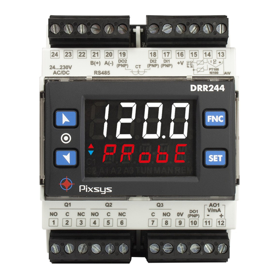
Introduction The process controller DRR244 is specifically conceived for application on control panels with DIN rail mounting. It stands out for the bright display which ensures optimal visibility and increased level of information for the operator beside a scrolling help function. -
Page 7: Precautions For Safe Use
According to European Directive 2002/96EC on waste electrical and electronic equipment and its implementation in accordance with national law, electric tools that have reached the end of their life must be collected separately and returned to an environmentally compatible recycling facility. User manual - DRR244 - 7... -
Page 8: Model Identification
Model Identification The DRR244 controller provides the following model: Power supply 24..230 VAC/VDC ±15% 50/60 Hz – 9 Watt/VA 1 analogue input + 2 relays 5 A + 1 relay 2 A + 2 SSR + 2 D.I. + 1 analogue output... -
Page 9: Programming Mode
When activated by a reader/interrogator supporting NFC-V protocol, App MyPixsys controller DRR244 is to be considered a VICC (Vicinity Inductively Coupled Card) according to ISO/IEC 15693 and it operates at a frequency of 13.56 MHz. The device does not intentionally emit radio waves. -
Page 10: Wiring Diagram
• When shielded cable is used, it should be grounded at one side only to avoid ground loop currents. AI1 V mA • It’s possible to select +V at 12Vdc or 24Vdc, by configuring parameter 282 (GROUP R - - Display and interface). V.out diSP. Shield/Schermo 10 - DRR244 - User manual... -
Page 11: Ct Input
Electrical endurance Q1, Q2: DC30 V t=7ms • 5A, 250 VAC, resistive loads, 10 operations. • 20/2A, 250 VAC, cosφ = 0.3, 10 operations. AC250V COS ø=0.4 DC30 V t=15ms Contact load current (A) User manual - DRR244 - 11... -
Page 12: Relay Output Q3
ON when alarm 3 is active. ON when the controller is executing an auto-tuning cycle. ON when “Manual” function is active. ON when the controller communicates through serial. Flashes when the remote setpoint is enabled. 12 - DRR244 - User manual... -
Page 13: Keys
• Running Tuning by serial input: Write 1 on word modbus 1216 (command 1) or 1217 (command 2): led switches ON and the procedure starts. Write 0 to stop the tuning. User manual - DRR244 - 13... -
Page 14: Tuning Once
Tuning once Set once on parameter 73 tun.1, or on parameter 98 tun.2. Autotuning procedure is executed only once at next DRR244 restart. If the procedure doesn’t work, will be executed at next restart. Synchronized tuning... -
Page 15: Automatic / Manual Regulation For % Output Control
PID immediately before breakage. Ex: on an extruder the command in percentage of the resistance (load) is maintained also in case of input sensor failure. User manual - DRR244 - 15... -
Page 16: Heater Break Alarm On Ct (Current Transformer)
H.b.A.t. an Heater Break Alarm. Funzionamento in doppia azione (caldo-freddo) DRR244 is suitable also for systems requiring a combined heating-cooling action. The command output has to be configured as PID for Heating (Par. 38 greater ac.t. 1 Heat P.b. -
Page 17: Latch On Function
Set virtual zero. Display shows zero. If “Virtual zero at start”is selected, point 4 To exit procedure press SET. must be repeated at each starting. 1 The tuning procedure starts by exiting the configuration after changing the parameter. User manual - DRR244 - 17... -
Page 18: Soft-Start Function
7.11 Soft-Start Function DRR244 is provided with two types of softstart selectable on parameter 264 (“Softstart Type”). SS.tY. 1 First selection ( ) enables gradient softstart. AAt starting the controller reaches setpoint basing GrAd. on the rising gradient set on parameter 266 (“Softstart Gradient”) in Unit/hour (ex. -
Page 19: Retransmission Function On Analogue Output
1 .L.L. r. 1 .u.L. 7.14 Timer functions The DRR244 integrates two timers that can be independent, sequential or looped together. Timer 1 is enabled on parameter 328 ; timer 2 on parameter 331 tmr. 1 . tmr.2. -
Page 20: Serial Communication
0 all the devices receive the command, but no response is expected. The baud rate is selected on parameter 319 (“Baud Rate”). bd.rt. DRR244 can introduce a delay (in milliseconds) of the response to the master request. This delay must be set on parameter 321 (“Serial Delay”). se.de. - Page 21 Bit0 = Digital inp. 1 Bit1 = Digital inp. 2 Outputs status (0=off, 1=on) Bit 0 = Q1 Bit 3 = DO1 1012 Bit 1 = Q2 Bit 4 = DO2 Bit 2 = Q3 User manual - DRR244 - 21...
- Page 22 R/W 0 1216 1=autotuning ON With synchronized Tune (par. 73 tun. 1 SYncH. 0=autotunig function OFF 1=command output OFF (forces the cooling) R/W 0 2=command output ON (forces the heating) 3=autotuning ON 4=autotuning ended 22 - DRR244 - User manual...
- Page 23 Alarm 2 lower setpoint if Par. 141 , with decimal point AL.2.F . A.band 1352 R/W EEPROM selection Alarm 3 lower setpoint if Par. 159 , with decimal point AL.3.F . A.band 1353 R/W EEPROM selection User manual - DRR244 - 23...
-
Page 24: Reading And Configuration Through Nfc
• Identify the position of the NFC antenna on the smartphone (usually behind the back cover) or to one of the sides in case of metal chassis. The DRR244’s antenna is placed on the frontal panel, between the function keys. -
Page 25: Access Configuration
The DRR244 will show a restart request, necessary to update the configuration with the new written modifications; if it does not restart, the DRR244 will continue to work with the previous configuration. -
Page 26: Parameters List Functioning
10.2 Parameters list functioning The controller DRR244 integrates many features that make the configuration parameters list very long. To make it more functional, the parameters list is dynamics and it changes as the user enables / disables the functions. Practically, using a specific function that occupies a given input (or output), the parameters referred to other functions of that resource are hidden to the user making the parameters list more concise. - Page 27 62.0 Hz 10.0Hz 62.0Hz 12.5 Hz 123 Hz 12.5Hz 123Hz 242 Hz 16.7 Hz (Default) Ideal for noises 242Hz 16. 7Hz 470 Hz (Max. speed conversion) filtering 50 / 60 Hz 470Hz 19.6 Hz 19.6Hz User manual - DRR244 - 27...
- Page 28 Action type to control process 1. Heating (N.A.) (Default) HEAt Cooling (N.C.) cooL Command Hysteresis 1 c.HY. 1 Hysteresis to control process 1 in ON/OFF. -9999..+9999 [digit ] (degrees.tenths for temperature sensors). Default 0.2. 1 p. 54 28 - DRR244 - User manual...
- Page 29 -60:00..60:00 mm:ss. Default: 00:00. Negative: delay when turning off output. Positive: delay when turning on output. Command Setpoint Protection 1 c.S.p. 1 Allows or not to modify command setpoint 1 value Modification allowed (Default) FrEE Protected Lock User manual - DRR244 - 29...
- Page 30 0 ON / OFF if t.i. equal to 0 (Default) 1...10000 [digit ] (degrees.tenths for temp. sensors). 1 p. 54 Integral Time 1 i.t. 1 Integral time for process 1 P.I.D. regulation (process intertia duration). 0.0...2000.0 secondi (0.0 = integral disabled), Default 0.0 30 - DRR244 - User manual...
- Page 31 Cycle time for cooling output in hating/cooling P.I.D. mode for process 1. 1-300 seconds (Default:10 s) Lower Limit Output Percentage 1 L.L.P. 1 Selects min. value for command output 1 percentage. 0%...100%, Default: 0%. User manual - DRR244 - 31...
- Page 32 Lev. 2 Lev. 5 (Default) Lev. 8 94÷97 Reserved Parameters - Group E Reserved parameters - Group E GROUP F - - Reserved res. 98÷122 Reserved Parameters - Group F Reserved parameters - Group F 32 - DRR244 - User manual...
- Page 33 ] (degrees for temp. sensors). Default 0.5. 1 p. 54 129 A. 1 .L.L. Alarm 1 Lower Limit Lower limit selectable for the alarm 1 setpoint. -9999..+30000 [digit ] (degrees for temp. sensors). Default 0. 1 p. 54 User manual - DRR244 - 33...
- Page 34 01 Message 16 (see table on paragraph 11.1) lb. 16 Custom message (modifiable by the user through the App or via modbus) user.l. 137÷140 Reserved Parameters - Group G Reserved parameters - Group G 34 - DRR244 - User manual...
- Page 35 ] (degrees for temp. sensors). Default 0.5. 1 p. 54 147 A.2.L.L. Alarm 2 Lower Limit Lower limit selectable for the alarm 2 setpoint. -9999..+30000 [digit ] (degrees for temp. sensors). Default 0. 1 p. 54 User manual - DRR244 - 35...
- Page 36 01 Message 20 (see table on paragraph 11.1) lb. 20 Custom message (modifiable by the user through the App or via modbus) user.l. 155÷158 Reserved Parameters - Group H Reserved parameters - Group H 36 - DRR244 - User manual...
- Page 37 Defines the output type if the alarm 3 is analogue. Output 0...10 V. Default 0.10 v Output 4...20 mA. 4.20ma 164 a.3.Hy. Alarm 3 Hysteresis Alarm 3 hysteresis. -9999..+9999 [digit ] (degrees for temp. sensors). Default 0.5. 1 p. 54 User manual - DRR244 - 37...
- Page 38 01 Message 20 (see table on paragraph 11.1) lb. 20 Custom message (modifiable by the user through the App or via modbus) user.l. 173÷176 Reserved Parameters - Group I Reserved parameters - Group I 38 - DRR244 - User manual...
- Page 39 Defines the output type if the alarm 4 is analogue. Output 0...10 V. Default 0.10 v Output 4...20 mA. 4.20ma 182 a. 4 .Hy. Alarm 4 Hysteresis Alarm 4 hysteresis. -9999..+9999 [digit ] (degrees for temp. sensors). Default 0.5. 1 p. 54 User manual - DRR244 - 39...
- Page 40 01 Message 20 (see table on paragraph 11.1) lb. 20 Custom message (modifiable by the user through the App or via modbus) user.l. 191÷194 Reserved Parameters - Group J Reserved parameters - Group J 40 - DRR244 - User manual...
- Page 41 Defines the output type if the alarm 5 is analogue. Output 0...10 V. Default 0.10 v Output 4...20 mA. 4.20ma 200 a.5.Hy. Alarm 5 Hysteresis Alarm 5 hysteresis. -9999..+9999 [digit ] (degrees for temp. sensors). Default 0.5. 1 p. 54 User manual - DRR244 - 41...
- Page 42 01 Message 20 (see table on paragraph 11.1) lb. 20 Custom message (modifiable by the user through the App or via modbus) user.l. 209÷212 Reserved Parameters - Group K Reserved parameters - Group K 42 - DRR244 - User manual...
- Page 43 232 d. i . 1 .c. Digital Input 1 Contact Defines the resting contact of the digital input 1. Normally open (Default) n.open Normally closed n.cLos. 233÷238 Reserved Parameters - Group M Reserved parameters - Group M User manual - DRR244 - 43...
- Page 44 GROUP O - - Reserved res. 247÷254 Reserved Parameters - Group O Reserved parameters - Group O GROUP P - - Reserved res. 255÷262 Reserved Parameters - Group P Reserved parameters - Group P 44 - DRR244 - User manual...
- Page 45 The elapsed time is saved every 10 minutes. Initial waiting time disabled: the controller starts immediately (Default) hh.mm Initial waiting time enabled. 00:01-24:00 273÷276 Reserved Parameters - Group Q Reserved parameters - Group Q User manual - DRR244 - 45...
- Page 46 Select the duration for the visualization of the user menu data, before returning to the default page. 3 seconds 1 minutes 1 MiN 5 minutes 5 seconds (Default) 5 MiN 10 minutes 10 seconds 10MiN 10 s Manual scroll 30 seconds MAn.Sc. 30 s 284 d.SP.F. Display Special Functions 46 - DRR244 - User manual...
- Page 47 Alarm disabled. (Default) Ampere 0.1-200.0 292 H.b.a.d. Heater Break Alarm Delay Heater Break Alarm and overcurrent alarm activation delay. mm:ss (Default: 01:00) 00:00-60:00 293÷297 Reserved Parameters - Group S Reserved parameters - Group S User manual - DRR244 - 47...
- Page 48 20 mA. 20 ma 21.5 mA. 21.5ma 303÷307 Reserved Parameters - Group T Reserved parameters - Group T GROUP U - - Reserved res. 308÷317 Reserved Parameters - Group U Reserved parameters - Group U 48 - DRR244 - User manual...
- Page 49 Selects the off-line tine. If there is no serial communication during the selected time, the controller switches-off the command output. Offline disabled (Default) tenths of second. 0.1-600.0 323÷327 Reserved Parameters - Group V Reserved parameters - Group V User manual - DRR244 - 49...
- Page 50 Singles. Timers work independently (Default) SinGL. Sequential. When timer 1 ends, timer 2 starts. SeQue. Loop. When a timer ends, another starts. LooP 335÷339 Reserved Parameters - Group W Reserved parameters - Group W 50 - DRR244 - User manual...
-
Page 51: Alarm Intervention Modes
AL. 1 .F. Ab.c.L.A. Command Spv Hysteresis parameter > 0 Alarm Spv Absolute alarm referred to command setpoint active below. Hysteresis value greater than “0” (Par. 128 > 0). a. 1 .HY Time Alarm output User manual - DRR244 - 51... -
Page 52: Band Alarm (Par. 123 = Band)
> 0). A. 1 .HY. Hysteresis parameter > 0 NB: with hysteresis value less than “0” ( < 0) the dotted line A. 1 .HY. moves under the alarm setpoint. Time Alarm output 52 - DRR244 - User manual... -
Page 53: Lower Deviation Alarm
By setting 0, no message will be displayed. While setting 21, the user will have up to 23 characters available to customize his message via the “MyPyxsys” App or via modbus. User manual - DRR244 - 53... -
Page 54: Fault Reporting Table
3 Changing the control setpoint, the alarm will be disabled. It will stay disabled as long as the parameters that created it are active. It only works with deviation alarms, band alarms and absolute alarms (referring to the control setpoint). 54 - DRR244 - User manual... - Page 55 User manual - DRR244 - 55...
- Page 56 1 Integral Time 1 i.t. 1 Derivative Time 1 d.t. 1 Dead Band 1 d.b. 1 Proportional Band Centered 1 p.b.c. 1 Off Over Setpoint 1 o.o.s. 1 Off Deviation Threshold 1 o.d.t. 1 56 - DRR244 - User manual...
- Page 57 Alarm 2 Led A.2.Ld. Alarm 2 Delay a.2.de. Alarm 2 Setpoint Protection A.2.S.p. Alarm 2 Label A.2.Lb. 155÷158 Reserved Parameters - Group H GROUP I - AL. 3 - ALARM 3 Alarm 3 Function AL.3.f. User manual - DRR244 - 57...
- Page 58 Alarm 4 Setpoint Protection A. 4 .S.p. Alarm 4 Label A. 4 .Lb. 191÷194 Reserved Parameters - Group J GROUP K - AL. 5 - Allarme 5 (solo su DRR244-13ABC e DRR244-23XX-T) Alarm 5 Function AL.5.f. Reserved rEs. Reserved rEs.
- Page 59 GROUP T - a.o. 1 - Retransmission 1 Retransmission 1 rtM. 1 Retransmission 1 Type r. 1 .ty. Retransmission 1 Lower Limit r. 1 . L.L. Retransmission 1 Upper Limit r. 1 . u.L. User manual - DRR244 - 59...
- Page 60 1 Time Base Timer 1 t.b.t. 1 Action Timer 1 a.tm. 1 Timer 2 tmr.2 Time Base Timer 2 t.b.t.2 Action Timer 2 a.tm.2 Timers Sequence tMr.s. 335÷339 Reserved Parameters - Group W 60 - DRR244 - User manual...
-
Page 61: Norme Di Sicurezza
Introduzione Il modello DRR244 è un regolatore per l’utilizzo in applicazioni su quadro di comando con montaggio a barra DIN e si distingue per il display performante che garantisce ottima leggibilità e aumenta le informazioni fruibili per l’operatore, in aggiunta ad un’utile funzione di Help a scorrimento. -
Page 62: Precauzioni Per L'uso Sicuro
WEEE Non smaltire le apparecchiature elettriche ed elettroniche tra i rifiuti domestici. Secondo al Direttiva Europea 2000/96/ce le apparecchiature esauste devono essere raccolte separatamente al fine di essere reimpiegate o riciclate in modo eco-compatibile. 62 - DRR244 - Manuale d’uso... -
Page 63: Identificazione Di Modello
Identificazione di modello Il regolatore DRR244 prevede il seguente modello: Alimentazione 24..230 VAC/VDC ±15% 50/60 Hz – 9 Watt/VA 1 analogue input + 2 relays 5 A + 1 relay 2 A + 2 SSR + 2 D.I. + 1 analogue output... -
Page 64: Modalità Di Programmazione
Modalità di programmazione da tastiera ..vedi paragrafo software LabSoftview ..vedi la sezione “Download” del sito www.pixsys.net ..attraverso il download dell’app dal Google Play Store®, vedi paragrafo Quando è interrogato da un lettore che supporta il protocollo NFC-V, il App MyPixsys dispositivo è... -
Page 65: Schema Di Collegamento
• Quando si usa cavo schermato, lo schermo deve essere collegato a terra ad una sola estremità. AI1 V mA • è possibile selezionare +V a 12Vdc o 24Vdc, configurando il parametro 282 (GRUPPO R - - Display e interfaccia). V.out diSP. Shield/Schermo Manuale d’uso - DRR244 - 65... -
Page 66: Ingresso Ct
DC30 V AC125 V AC125V COS ø=0.4 Portata contatti: DC30 V t=7ms • 5A, 250Vac, carico resistivo, 10 operazioni. • 20/2A, 250Vac, cosφ=0.3, 10 operazioni. AC250V COS ø=0.4 DC30 V t=15ms Contact load current (A) 66 - DRR244 - Manuale d’uso... -
Page 67: Uscite Relè Q3
Acceso quando l’allarme 3 è attivo. Acceso quando il regolatore sta eseguendo un ciclo di auto-tuning. Acceso all’attivazione della funzione “Manuale”. Acceso quando il regolatore comunica via seriale. Lampeggia quando il setpoint remoto è abilitato. Manuale d’uso - DRR244 - 67... -
Page 68: Tasti
• Lancio del Tuning da ingresso seriale: Scrivere 1 sulla word modbus 1216 (comando 1) o 1217 (comando 2): il led si accende e la procedura ha inizio. Scrivere 0 per fermare il tuning. 68 - DRR244 - Manuale d’uso... -
Page 69: Tuning Once
239 d. i . 1 .F. d. i .2.F • : cambio setpoint a due soglie: con ingresso digitale attivo Il DRR244 regola su SET2, altrimenti 2t.Sw. regola su SET1; • : cambio di 2 setpoint da ingresso digitale con comando ad impulso;... -
Page 70: Regolazione Automatico / Manuale Del Controllo % Uscita
• : il DRR244 esegue una regolazione di tipo freddo con ingresso digitale attivo, altrimenti la Act.ty. regolazione è di tipo caldo; • : funzione tara di zero: porta l’ingresso analogico a 0. A.i. 0 • : Permette il reset delle uscite nel caso fosse impostato il riarmo manuale per le gli allarmi ed M.reS. -
Page 71: Heater Break Alarm Su Ct
0 è possibile visualizzare la corrente assorbita senza mai H.b.A.t. generare Heater Break Alarm. Funzionamento in doppia azione (caldo-freddo) Il DRR244 è adatto alla regolazione anche su impianti che prevedano un’azione combinata caldo-freddo. L’uscita di comando deve essere configurata in PID caldo (Par. 38 maggiore di ac.t. -
Page 72: Funzione Latch On
. 1 Per uscire dalla procedura premere SET. Fissa il valore sul massimo. Nel caso di impostazione con “zero virtuale” Il display visualizza HiGh. posizionare il sensore nel punto di zero. 72 - DRR244 - Manuale d’uso... -
Page 73: Funzione Soft-Start
Nel caso di “0 virtuale” allo start, il punto 4 va eseguito ad ogni riaccensione. 7.11 Funzione Soft-Start L’ DRR244 implementa due tipologie di softstart selezionabili sul parametro 264 (“Softstart Type”). SS.tY. 1 La prima selezione ( ) abilita il softstart a gradiente. All’accensione, il regolatore, per raggiungere GrAd. -
Page 74: Funzione Ritrasmissione Su Uscita Analogica
1 .u.L. ingresso. 7.14 Funzioni timer Il DRR244 implementa due timer che possono essere indipendenti, sequenziali o in loop tra loro. Il timer 1 viene abilitato sul parametro 328 ; il timer 2 sul parametro 331 tmr. 1 . -
Page 75: Comunicazione Seriale
320 (Serial Port Parameters). s.p.p. Il DRR244 può introdurre un ritardo (in millisecondi) della risposta alla richiesta del Master. Tale ritardo deve essere impostato sul parametro 321 (“Serial Delay”). se.de. Ad ogni variazione dei parametri lo strumento salva il valore in memoria EEPROM (100000 cicli di scrittura), mentre il salvataggio dei setpoint avviene con un ritardo di 10 secondi dall’ultima modifica. - Page 76 Bit0 = Ingresso dig. 1 Bit1 = Ingresso dig. 2 Stato uscite (0=off, 1=on) Bit 0 = Q1 Bit 3 = DO1 1012 Bit 1 = Q2 Bit 4 = DO2 Bit 2 = Q3 76 - DRR244 - Manuale d’uso...
- Page 77 1216 1=autotuning ON Con Tune sincronizzato (par. 73 tun. 1 SYncH. 0=funzione autotuning OFF 1=uscita di comando spenta (forza il raffreddamento) R/W 0 2=uscita di comando accesa (forza il riscaldamento) 3=autotuning ON 4=autotuning terminato Manuale d’uso - DRR244 - 77...
- Page 78 Setpoint inferiore Allarme 2 se Par. 141 , con selezione del AL.2.F . A.band 1352 R/W EEPROM punto decimale Setpoint inferiore Allarme 3 se Par. 159 , con selezione del AL.3.F . A.band 1353 R/W EEPROM punto decimale 78 - DRR244 - Manuale d’uso...
-
Page 79: Lettura E Configurazione Via Nfc
Procedura: • Identifi care la posizione dell’antenna NFC nel telefono (solitamente centrale, dietro la cover posteriore, o ad una delle estremità nel caso di chassis metallici). L’antenna del regolatore DRR244 è posizionata sul frontale, tra i tasti up e down. -
Page 80: Accesso Alla Configurazione
DRR244 visualizzerà una richiesta di riavvio, necessaria per aggiornare la configurazione con le modifiche appena scritte; se non verrà riavviato, ATR 244 continuerà a funzionare con la precedente configurazione. -
Page 81: Funzionamento Della Lista Parametri
10.2 Funzionamento della lista parametri Il regolatore DRR244 integra molte funzionalità che rendono di fatto la lista dei parametri di configura- zione molto lunga. Per renderla più funzionale, la lista parametri è dinamica, cioè si adatta man mano che l’utente va ad abilitare/ disabilitare le funzioni necessarie. In pratica, utilizzando una specifica funzione che va ad occupare un determinato ingresso (o un’uscita), i parametri che fanno riferimento... - Page 82 Conversion Frequency AI1 c.Fr. 1 Frequenza di campionamento del convertitore analogico/digitale per AI1. Aumentando la velocità di conversione diminuisce la stabilità di lettura (es: per transitori veloci come la pressione consigliabile aumentare la frequenza di campionamento). 82 - DRR244 - Manuale d’uso...
- Page 83 La corrispondenza delle funzioni/uscite resta comunque quella indicata nelle tabelle qui sopra. Reserved rEs. Parametro riservato. Manuale d’uso - DRR244 - 83...
- Page 84 0%, spento se 100% e lampeggiante tra 1% e 99%. Acceso a contatto chiuso o SSR acceso. Se comando AO1, acceso con uscita al 100%, c.c. spento se 0% e lampeggiante tra 1% e 99%. (Default) 84 - DRR244 - Manuale d’uso...
- Page 85 1 Imposta la deviazione dal setpoint di comando 1 come soglia usata dall’ autotuning, per il calcolo dei parametri PID 0-10000 [digit ] (gradi.decimi per sensori di temperatura). Default: 30.0. 1 p. 109 Manuale d’uso - DRR244 - 85...
- Page 86 Moltiplicatore di banda proporzionale in modalità PID caldo / freddo per il processo 1. La banda proporzionale per l’azione freddo è data dal valore del parametro P.B. 1 moltiplicato per questo valore. 1.00..5.00. Default: 1.00 86 - DRR244 - Manuale d’uso...
- Page 87 Lev . 8 Lev . 5 ( 94÷97 Reserved Parameters - Group E Parametri riservati - Gruppo E. GRUPPO F - - Reserved res. 98÷122 Reserved Parameters - Group F Parametri riservati - Gruppo F. Manuale d’uso - DRR244 - 87...
- Page 88 (N.C. Threshold Variation) inibito dopo variazione set di comando 3 p. 109 n.c.tH.V . 127 rEs. Reserved Parametro riservato. 128 a. 1 .Hy. Alarm 1 Hysteresis Isteresi allarme 1. -9999..+9999 [digit ] (gradi.decimi per sensori di temperatura). Default 0.5. 1 p. 109 88 - DRR244 - Manuale d’uso...
- Page 89 Messaggio 1 (Vedi tabella paragrafo 12.1) .. Lb. 01 Messaggio 20 (Vedi tabella paragrafo 12.1) Lb. 20 Messaggio personalizzato (modificabile dall’utente attraverso l’App o via modbus) user.l. 137÷140 Reserved Parameters - Group G Parametri riservati - Gruppo G. Manuale d’uso - DRR244 - 89...
- Page 90 (N.C. Threshold Variation) inibito dopo variazione set di comando 3 p. 109 n.c.tH.V . 145 rEs. Reserved Parametro riservato. 146 a.2.Hy. Alarm 2 Hysteresis Isteresi allarme 2. -9999..+9999 [digit ] (gradi.decimi per sensori di temperatura). Default 0.5. 1 p. 109 90 - DRR244 - Manuale d’uso...
- Page 91 Messaggio 1 (Vedi tabella paragrafo 12.1) Lb. 01 Messaggio 20 (Vedi tabella paragrafo 12.1) Lb. 20 Messaggio personalizzato (modificabile dall’utente attraverso l’App o via modbus) user.l. 155÷158 Reserved Parameters - Group H Parametri riservati - Gruppo H. Manuale d’uso - DRR244 - 91...
- Page 92 Definisci la tipologia di uscita, qualora l’allarme 3 fosse di tipo analogico. Uscita 0..10 V. Default 0.10 v Uscita 4..20 mA. 4.20ma 164 a.3.Hy. Alarm 3 Hysteresis Isteresi allarme 3. -9999..+9999 [digit ] (gradi.decimi per sensori di temperatura). Default 0.5. 1 p. 109 92 - DRR244 - Manuale d’uso...
- Page 93 Imposta il messaggio da visualizzare in caso di intervento allarme 3. Disabilitato. (Default) disab. Messaggio 1 (Vedi tabella paragrafo 12.1) Lb. 01 Messaggio 20 (Vedi tabella paragrafo 12.1) Lb. 20 Messaggio personalizzato (modificabile dall’utente attraverso l’App o via modbus) user.l. Manuale d’uso - DRR244 - 93...
- Page 94 3 p. 109 n.c.tH.V . 181 A. 4 .o.t. Alarm 4 Output Type Definisci la tipologia di uscita, qualora l’allarme 4 fosse di tipo analogico. Uscita 0..10 V. Default 0.10 v Uscita 4..20 mA. 4.20ma 94 - DRR244 - Manuale d’uso...
- Page 95 Valore positivo: ritardo in fase di entrata nello stato di allarme. 189 A. 4 .S.p. Alarm 4 Setpoint Protection Consente o meno di variare il valore del setpoint dell’ allarme 4. Modificabile dall’utente (Default) FrEE Protetto Lock Protetto e non visualizzato HidE Manuale d’uso - DRR244 - 95...
- Page 96 (N.C. Threshold) operativo al raggiungimento dell’allarme 2 p. 109 n.c. tH. (N.O. Threshold Variation) inibito dopo variazione set di comando 3 p. 109 n.o.tH.V . (N.C. Threshold Variation) inibito dopo variazione set di comando 3 p. 109 n.c.tH.V . 96 - DRR244 - Manuale d’uso...
- Page 97 Valore positivo: ritardo in fase di entrata nello stato di allarme 207 A.5.S.p. Alarm 5 Setpoint Protection Consente o meno di variare il valore del setpoint dell’ allarme 5. Modificabile dall’utente (Default) FrEE Protetto Lock Protetto e non visualizzato HidE Manuale d’uso - DRR244 - 97...
- Page 98 START automaticamente: per questa operazione è richiesto l’intervento dell’utente. 232 d. i . 1 .c. Digital Input 1 Contact Definisce il contatto a riposo dell’ ingresso digitale 1. Normalmente aperto (Default) n.open Normalmente chiuso n.cLos. 98 - DRR244 - Manuale d’uso...
- Page 99 GRUPPO O - - Reserved res. 247÷254 Reserved Parameters - Group O Parametri riservati - Gruppo O. GRUPPO P - - Reserved res. 255÷262 Reserved Parameters - Group P Parametri riservati - Gruppo P Manuale d’uso - DRR244 - 99...
- Page 100 Il tempo trascorso viene memorizzato ogni 10 minuti. 00:00 Attesa iniziale disabilitata: il regolatore va subito in start (Default) 00:01-24:00 hh:mm Attesa iniziale abilitata 273÷276 Reserved Parameters - Group Q Parametri riservati - Gruppo Q 100 - DRR244 - Manuale d’uso...
- Page 101 Gradiente di salita, tempo di mantenimento e gradiente di discesa. r.f .G.m.t. 282 v.out Voltage Output Seleziona la tensione sui morsetti di alimentazione delle sonde e delle uscite digitali (SSR). 12 volt (Default) 12 v 24 volt 24 v Manuale d’uso - DRR244 - 101...
- Page 102 Current Transformer Value Seleziona il fondo-scala del trasformatore amperometrico Ampere (Default: 50) 1..200 289 rEs. Reserved Parametro riservato. 290 H.b.a.t. Heater Break Alarm Threshold Soglia di intervento del Heater Break Alarm Allarme disabilitato. (Default:) Ampere. 0.1-200.0 102 - DRR244 - Manuale d’uso...
- Page 103 Se l’uscita di ritrasmissione è 0-20 mA o 4-20 mA: 0 mA. Default 0 ma 4 mA. 4 ma 20 mA. 20 ma 21.5 mA. 21.5ma 303÷307 Reserved Parameters - Group T Parametri riservati - Gruppo T. Manuale d’uso - DRR244 - 103...
- Page 104 Seleziona il tempo di off-line. Se non c’è comunicazione seriale entro il tempo impostato, il regolatore spegne l’uscita di comando. Offline disabilitato (Default) decimi di secondo. 0.1-600.0 323÷327 Reserved Parameters - Group V Parametri riservati - Gruppo V. 104 - DRR244 - Manuale d’uso...
- Page 105 SinGL. Sequential. Allo scadere del timer 1 parte il timer 2. SeQue. Loop. Allo scadere di un timer, parte l’altro di seguito LooP 335÷339 Reserved Parameters - Group W Parametri riservati - Gruppo W. Manuale d’uso - DRR244 - 105...
-
Page 106: Modi D'intervento Allarme
Command Spv Hysteresis parameter > 0 Alarm Spv Allarme assoluto riferito al setpoint di comando attivo sotto. Valore di isteresi maggiore di “0” (Par. 128 > 0). a. 1 .HY Time Alarm output 106 - DRR244 - Manuale d’uso... -
Page 107: Allarme Di Banda (Par. 123 = Band)
> 0). a. 1 .HY Hysteresis parameter > 0 N.B.: con isteresi minore di “0” ( < 0) la linea tratteggiata si sposta a. 1 .HY sopra il Setpoint di allarme. Time Alarm output Manuale d’uso - DRR244 - 107... -
Page 108: Allarme Di Deviazione Inferiore
Impostando 0 nessun messaggio verrà visualizzato, mentre impostando 21 l’utente avrà a disposizione fino a 23 caratteri per personalizzare il proprio messaggio attraverso l’app MyPyxsys o via modbus. 108 - DRR244 - Manuale d’uso... -
Page 109: Tabella Segnalazioni Anomalie
3 In caso di variazione del setpoint di comando, l’allarme viene inibito finchè non rientra dalle condizioni che eventualmente l’hanno generato. Funziona solo con allarmi di deviazione, banda e assoluto riferito al setpoint di comando. Manuale d’uso - DRR244 - 109... - Page 110 110 - DRR244 - Manuale d’uso...
- Page 111 1 Integral Time 1 i.t. 1 Derivative Time 1 d.t. 1 Dead Band 1 d.b. 1 Proportional Band Centered 1 p.b.c. 1 Off Over Setpoint 1 o.o.s. 1 Off Deviation Threshold 1 o.d.t. 1 Manuale d’uso - DRR244 - 111...
- Page 112 Alarm 2 Led A.2.Ld. Alarm 2 Delay a.2.de. Alarm 2 Setpoint Protection A.2.S.p. Alarm 2 Label A.2.Lb. 155÷158 Reserved Parameters - Group H GRUPPO I - AL. 3 - Allarme 3 Alarm 3 Function AL.3.f. 112 - DRR244 - Manuale d’uso...
- Page 113 Alarm 4 Setpoint Protection A. 4 .S.p. Alarm 4 Label A. 4 .Lb. 191÷194 Reserved Parameters - Group J GRUPPO K - AL. 5 - Allarme 5 (solo su DRR244-13ABC e DRR244-23XX-T) Alarm 5 Function AL.5.f. Reserved rEs. Reserved rEs.
- Page 114 GRUPPO T - a.o. 1 - Retransmission 1 Retransmission 1 rtM. 1 Retransmission 1 Type r. 1 .ty. Retransmission 1 Lower Limit r. 1 . L.L. Retransmission 1 Upper Limit r. 1 . u.L. 114 - DRR244 - Manuale d’uso...
- Page 115 1 Time Base Timer 1 t.b.t. 1 Action Timer 1 a.tm. 1 Timer 2 tmr.2 Time Base Timer 2 t.b.t.2 Action Timer 2 a.tm.2 Timers Sequence tMr.s. 335÷339 Reserved Parameters - Group W Manuale d’uso - DRR244 - 115...
-
Page 116: Consignes De Sécurité
Introduction Le modèle DRR244 est un régulateur pour une utilisation dans les applications de panneau de commande avec montage sur barre DIN et se distingue par son affichage performante qui garantit une excellente lisibilité et augmente les informations que peuvent être utilisées par l’opérateur, en plus d’une utile fonction d’aide à... -
Page 117: Précautions Pour L'usage En Toute Sécurité
2002/96 / CE concernant les déchets d’équipements électriques et électroniques ainsi que leur mise en œuvre conformément au droit national, les outils électriques arrivés en fin de vie doivent être collectés séparément et renvoyés à un centre de recyclage respectueux de l’environnement. Manuel d’utilisation - DRR244 - 117... -
Page 118: Identification Du Modèle
Identification du modèle Le régulateur DRR244 prévoit le modèle suivant: Alimentation 24..230 VAC/VDC ±15% 50/60 Hz – 9 Watt/VA 1 entrée analogique + 2 relais 5 A + 1 relais 2 A + 2 SSR + 2 D.I. + 1 sortie... -
Page 119: Mode De Programmation
..voir le paragraphe 10 software LabSoftview ..voir la section “Download” du site www.pixsys.net ..à travers le download de l’application de Google Play Store®, voir le par. 9 Lorsqu’il est interrogé par un lecteur qui supporte le protocole NFC-V, l’appareil doit être considéré... -
Page 120: Plan Des Connexions
• Quand on utilise un câble blindé, le blindage doit être raccordé à la terre à une seule extrémité. AI1 V mA • + V peut être sélectionné à 12Vdc ou 24Vdc en configurant le paramètre (GROUPE R - - Affichage et interface). V.out diSP. Shield/Schermo 120 - DRR244 - Manuel d’utilisation... -
Page 121: Entrée Ct
Electrical endurance Q1, Q2: DC30 V t=7ms • 5A, 250 VAC, charge résistive, 10⁵ operations. • 20/2 A, 250 VAC, cosφ = 0.3, 10⁵ operations. AC250V COS ø=0.4 DC30 V t=15ms Contact load current (A) Manuel d’utilisation - DRR244 - 121... -
Page 122: Uscite Relè Q3
2A 230V Resistive Voir le tableau ci-dessous. Electrical endurance Q1, Q2: • 2A, 250 VAC, charge résistive, 10⁵ operations. • 20/2 A, 250 VAC, cosφ = 0.3, 10⁵ operations. Notes / Mises à jour 122 - DRR244 - Manuel d’utilisation... - Page 124 Avant d’utiliser le dispositif lire avec attention les renseignements de sûreté et installation contenus dans ce manuel. PIXSYS s.r.l. www.pixsys.net sales@pixsys.net - support@pixsys.net online assistance: http://forum.pixsys.net via Po, 16 I-30030 Mellaredo di Pianiga, VENEZIA (IT) Tel +39 041 5190518 2300.10.304-RevA...
Need help?
Do you have a question about the DRR244 and is the answer not in the manual?
Questions and answers