Table of Contents
Advertisement
Quick Links
Advertisement
Table of Contents

Related Manuals for Pixsys DRR245


Summary of Contents for Pixsys DRR245
- Page 1 DRR245 Controller Start guide...
-
Page 3: Table Of Contents
Table of contents Introduction ............................6 Safety guide lines ..........................6 Model identification ........................7 Technical Data..........................7 General data .........................7 Hardware data ........................7 Software data ........................8 Dimensions and Installation ......................9 Electrical wirings ..........................10 Wiring diagram........................10 6.1.a Power supply ......................11 6.1.b AN1 analogue imput..................11 6.1.c Example of connection for linear input Volt and mA .......12 6.1.d... - Page 4 10 Serial Communication ........................ 26 11 Enter Configuration parameters ....................32 11.1 Loading default values ....................32 12 Table of configuration parameters ..................33 13 Alarm Intervention Modes ......................48 13.a Absolute Alarm or Threshold Alarm ( a. AL. selection) ........48 13.b Absolute Alarm or Threshold Alarm Referring to Setpoint Command ( a.c.AL.
-
Page 6: Introduction
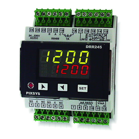
Controller DRR245 is specifically conceived for application on control panels with DIN rail mounting. Pixsys makes available in a single device all the options relevant to sensor input and actuators command, in addition to the extended power range 24..230 Vac/ Vdc. -
Page 7: Model Identification
0-10 V: Ri>110KΩ 0-40mV, amperometric 0-20 mA: Ri<5Ω transformer T.A. 50mA 1024 4-20 mA: Ri<5Ω points 0-40 mV: Ri>1MΩ Potentiometers: 6 KΩ, 150 KΩ. Relay 2 relays Configurable for Contacts 5A/250V~Resistite output command or alarm. loads User manual - DRR245 7... -
Page 8: Software Data
Derivative time 0,0..999,9 sec. (0 excludes derivative function) Manual or automatic Tuning, configurable alarms, Controller protection of command and alarm setpoints, activation of functions functions via digital input, preset cycle with Start / Stop. 8 - DRR245 - User manual... -
Page 9: Dimensions And Installation
72 mm 64 mm Extractable terminal blocks Din rail mounting guide EN50022 Morsettiere Estraibili Attacco a guida DIN EN50022 Memory Card (Optional) Memory Card (Optional) Cod. Memory 2100.30.002 with battery / con batteria Cod. Memory 2100.30.003 User manual - DRR245 9... -
Page 10: Electrical Wirings
• Separate control lines from the power wires. • Avoid the proximity of remote control switches, electromagnetic meters, powerful engines. • Avoid the proximity of power groups, especially those with phase control. Wiring diagram 10 - DRR245 - User manual... -
Page 11: Power Supply
• Select internal jumper JP3 as in the figure. Rosso RED/ROSSO WHITE/BIANCO RED/ROSSO Shield/Schermo For thermoresistances NTC, PTC, PT500, PT1000 e potentiometers. When shielded cable is used, it should be grounded at one side only to avoid ground loop currents. User manual - DRR245 11... -
Page 12: Example Of Connection For Linear Input Volt And Ma
A= Sensor output Alimentazione esterna B= Sensor ground For signals 0/4..20 mA with two-wire sensor. 4...20mA Comply with polarity: A= Sensor output C= Sensor power supply (12Vdc / 30mA) PRESSURE TRANSMITTER / SENSORE DI PRESSIONE 12 - DRR245 - User manual... -
Page 13: Serial Input
AC125V COS ø=0.4 DC30 V t=7ms AC250V COS ø=0.4 DC30 V t=15ms Contact load current (A) 6.1.f SSR output +10,5V SSR command 10,5V/30mA. Short-circuit pins 9 and 10 as in the figure to use SSR output User manual - DRR245 13... -
Page 14: G Ma / Volt Output
6.1.j Digital Input 2 Combined use of digital input and T.A. input Digital input according to parameter dGt.i. This combined use is possible only with sensors TC, (NpN) 0..10V, 0/4..20mA, 0..40mV. 14 - DRR245 - User manual... -
Page 15: Display And Key Functions
(close) for a motorised valve command. A1 A2 A3 ON when the corresponding alarm is on. ON when the “Manual” function is on. ON when the controller is running an “Autotune” cycle. ON when the controller communicates via serial port. User manual - DRR245 15... -
Page 16: Keys
Increases or decreases Value on display 2 changes. the alarm setpoint value. Auto-Tuning Tuning procedure calculates the controller parameters and can be manual or automatic according to selection on parameter 57 ( tunE 16 - DRR245 - User manual... -
Page 17: Manual Tuning
Autotuning, manual or automatic, works ONLY when the Soft-Start time is expired and if parameter 59 is set on and parameter 63 op.mo. cont. ma.ti. different from 0. User manual - DRR245 17... -
Page 18: Automatic / Manual Regulation For % Output Control
On expiry, the command output is disabled and controller displays stop Cycle starts at each activation of the controller, or via digital input if it is enabled for this type of functioning (see parameter 61 dGt.i. 18 - DRR245 - User manual... - Page 19 SET2. The autotuning (manual or automatic) works only if SET2 is being regulated. If the autotuning is launched during regulation on SET1 it doesn’t start until the regulation pass to SET2. User manual - DRR245 19...
-
Page 20: Memory Card (Optional)
Enter configuration and change at least one parameter. Exit configuration. Changes are stored automatically. If on activation the controller does not display memo it means no data have been saved on the memory card, but it is possible to update values. 20 - DRR245 - User manual... -
Page 21: Latch On Functions
Display shows . NB: uirt For selection of To exit procedure press u.0in. the procedure in point 4 should be followed on each re-activation. The tuning procedure starts by exiting the configuration after changing the parameter. User manual - DRR245 21... -
Page 22: Loop Break Alarm On Current Trasformer
2 shows the current on display 2 the output in amperes ( >0). t.a. percentage, auto / man The value is also maintained selection, setpoint and alarms. when no current circulates on the load. 22 - DRR245 - User manual... -
Page 23: Digital Imput Functions
0 it is possible to visualize the current L.b.A.t. absorbed without generating the Loop Break Alarm. Digital Imput Functions On DRR245 model, digital input can be enabled by using parameters 59 op.mo. and 61 dGt.i. • Parameter 59 op.mo. -
Page 24: Dual Action Heating-Cooling
Dual Action Heating-Cooling DRR245 is suitable also for systems requiring a combined heating-cooling action. Command output must be configured as Heating P.I.D. ( Act.t. HEAT and with a greater than 0), and one of the alarms ( ) must P.b. - Page 25 P.I.D. time cycle basing on the type of cooling fluid: P.b.M. co.t.c. Cooling fluid type coo.F. P.b.M. co.t.c 1.00 1.25 Water 2.50 Once selected, parameter , parameters coo.f. P.b.M. oud.b. co.t.c. however be changed. User manual - DRR245 25...
-
Page 26: Serial Communication
(broadcast mode), while with 0 all the devices receive the command, but no response is expected. DRR245 can introduce a delay (in milliseconds) in the response to the master request. This delay must be set on parameter 72 Each parameter change se.de. - Page 27 Bit 0 = Alarm 1 Bit 1 = Alarm 2 Manual reset: write 0 to reset all alarms. 1013 In reading (0 = Not resettable, 1 = Resettable) Bit 0 = Alarm 1 Bit 1 = Alarm 2 User manual - DRR245 27...
- Page 28 1019 0 = Automatic 1 = Manual 1020 T.A. current ON (Ampere with tenths) 1021 T.A. current OFF (Ampere with tenths) 1022 OFF LINE* time (milliseconds) 1023 Instant Current (Ampere) 1024 Digital Input State 28 - DRR245 - User manual...
- Page 29 First word display 1 (ascii) 3002 Second word display 1 (ascii) 3003 Third word display 1 (ascii) 3004 Fourth word display 1 (ascii) 3005 Fifth word display 1 (ascii) 3006 Sixth word display 1 (ascii) User manual - DRR245 29...
- Page 30 Bit 0 = Relay Q1 Bit 1 = Relay Q2 3020 Word SSR serial (0 = Off, 1 = On) 3021 Word output 0..10 V serial (0..10000) 3022 Word output 4..20 mA serial (0..10000) 30 - DRR245 - User manual...
- Page 31 ** By writing 1 on this word, the effects of the writing are cancelled on all the Modbus addresses from 3001 to 3022. Control therefore returns to the controller. *** Parameters modified using serial address 4001 to 4072 will be stored on eeprom only after 10” since last writing of one parameter. User manual - DRR245 31...
-
Page 32: Enter Configuration Parameters
1st digit blinking, while display 2 shows PASS to the next one with |. Change blinking digit and move Enter password: 9999 | to confirm Turn off and restart the Device loads default settings. instrument. 32 - DRR245 - User manual... -
Page 33: Table Of Configuration Parameters
ALARM 1 ALARM 2 c. o1 c. o2 c.SSr Q1 (open) c.uAL. Q2 (close) 4..20 mA c. 4 .20 0..20 mA c.0.20 0..10 mV c.0. 1 0 Do not select if process retransmission function is used. User manual - DRR245 33... - Page 34 Select type of visualized decimal point Default 1 Decimal 2 Decimals 0.00 3 Decimals 0.000 Lower Limit Setpoint Lo.L.S. Lower limit selectable for setpoint -999..+9999 [digit ] (degrees.tenths for temperature sensors), Default: 1 p. 55 34 - DRR245 - User manual...
- Page 35 Gain Calibration G.cAL. Percentage value that is multiplied for the process value (allows to calibrated the working point) -99.9%..+100.0% (Default = 0.0) ex: to correct the range from 0..1000°C showing 0..1010°C, set the parameter to -1.0. User manual - DRR245 35...
- Page 36 P.I.D. and represents the delay between opening and closure of the two contacts -180..+180 seconds (tenths of second in case of servo valve). Negative: delay in switching off phase. Positive: delay in activation phase. Default: 0. 36 - DRR245 - User manual...
- Page 37 Select max. value for command output percentage 0..100%, Default: 100%. Es: with selected as 0..10 V and as 90%, command output can c.out o.PoL. modulate from a min. of 0 V to a max. of 9 V. User manual - DRR245 37...
- Page 38 Open contact (Default) c.o. Closed contact c.c. Alarm 1 Led a. 1 .Ld. Defines the state of OUT2 led corresponding to the relative contact ON with open contact c.o. ON with closed contact (Default) c.c. 38 - DRR245 - User manual...
- Page 39 (N.C. start) Normally closed, active at start n.c. s (N.O. threshold) Normally open, active on reaching alarm 2 p. 55 n.o. t (N.C. threshold) Normally closed, active on reaching alarm 2 p. 55 n.c. t User manual - DRR245 39...
- Page 40 Alarm 2 set protection. Does not allow operator to change value set Modification allowed (Default) free Protected Lock Protected and not visualized Hide Current Transformer t.a. Activation and scale range of current transformer 0 Disabled. 1-200 Ampere. Default: 0 40 - DRR245 - User manual...
- Page 41 Dead band combination for heating / cooling action in heating / cooling P.I.D. mode (dual action). -20.0-50.0% of proportional band value (Default: 0). Negative indicates dead band value. Positive means overlap. Cooling Cycle Time co.t.c. Cycle time for cooling output 1-300 seconds, Default: 10. User manual - DRR245 41...
- Page 42 16.7 Hz (Default) Ideal for filtering noises 50 / 60 Hz 16. 7 H. 12.5 Hz 12.5H. 10 Hz 10 H. 8.33 Hz 8.33H. 6.25 Hz 6.25H. 4.17 Hz (Minimum speed conversion) 4. 1 7H. 42 - DRR245 - User manual...
- Page 43 Synchronized (see word modbus 1025) sYnc. Setpoint Deviation Tune s.d.tu. Select the deviation from the command setpoint for the threshold used by autotuning to calculate the P.I.D. parameters 0-5000 [digit ] (degrees.tenths for temperature sensors). Default: 10. User manual - DRR245 43...
- Page 44 Lock conversion N.C. (stop conversion and display value with L.c.n.c. N.C.) Manual Tune (by digital input) tune Automatic / Manual Impulse (if enabled on parameter 60) a.ma.i. Automatic / Manual Contact (if enabled on parameter 60) a.ma.c. 44 - DRR245 - User manual...
- Page 45 1 Setpoint, 2 Process 1.s.2.P. 1 Setpoint, 2 Hide after 3 sec. 1.s.2.H. 1 Process, 2 Ampere (T.A. input) 1.p.2.a. 1 Process, 2 Emissivity for infrared sensors 1.p.2.E Degree deGr. Select degree type Centigrade (Default) c Fahrenheit f User manual - DRR245 45...
- Page 46 -999..+9999 [digit 1000. Baud Rate bd.rt. Select baud rate for serial communication 4.800 Bit/s 4.8 k 9.600 Bit/s 9.6 k 19.200 Bit/s (Default) 19.2k 28.800 Bit/s 28.8k 39.400 Bit/s 39. 4 k 57.600 Bit/s 57.6k 46 - DRR245 - User manual...
- Page 47 Selects min. value for command output percentage 0 – 100%, Default: 0%. Ex: with selected as 0..10 V and set at 10%, command output c.out L.L.o.P. can change from a min. of 1 V to a max. of 10 V. User manual - DRR245 47...
-
Page 48: Alarm Intervention Modes
Absolute alarm with controller in parameter > 0 cooling functioning (par. 11 Act.t. selected ) and hysteresis value CooL Alarm Spv than “0” (par. 28 > 0). A. 1 .HY. N.B.* Alarm output 48 - DRR245 - User manual... -
Page 49: Absolute Alarm Or Threshold Alarm Referring To Setpoint Command ( Selection)
Alarm Spv greater than “0” (par. 28 > 0). A. 1 .HY. The command set can be changed by pressing the arrow keys on front Time panel or using serial port RS485 commands. Alarm output N.B.* User manual - DRR245 49... -
Page 50: Band Alarm ( Selection)
A. 1 .HY. Hysteresis parameter N.B.* < 0 Time Alarm output * The example refers to alarm 1; the function can also be enabled for alarms 2 and 3 on models that include it. 50 - DRR245 - User manual... -
Page 51: Upper Deviation Alarm ( H.d.al. Selection)
Upper deviation alarm value of alarm Alarm Spv Alarm Spv Alarm Spv Alarm Spv setpoint less than “0” and hysteresis Hysteresis value greater than “0” (par. 28 parameter A. 1 .HY. > 0 > 0). N.B.** Time Alarm output User manual - DRR245 51... -
Page 52: Lower Deviation Alarm ( L.d.al. Selection)
** a) The example refers to alarm 1; the function can also be enabled for alarms 2 and 3 on models that include it. b) With hysteresis value less than “0” ( A. 1 .HY. < 0) the broken line moves under the alarm setpoint. 52 - DRR245 - User manual... -
Page 53: Table Of Anomaly Signals
Check if the configuration Possible loss of calibration parameters are correct. SYS.E values. E-05 Thermocouple open or Check the connection with the temperature outside of limits. sensors and their integrity. prb. E-08 Missing calibration data. Call Assistance. SYS.E User manual - DRR245 53... -
Page 54: Configuration Easy-Up
Configuration EASY-UP To simplify the setting of parameters and the integration of the different components involved in the control system, Pixsys introduces the EASY-UP coding which allows to set sensors and/or command outputs in one single step. By means of the code listed in the data sheet enclosed to the sensor or actuator (SSR, motorized valve, etc.) the EASY-UP coding will set the relevant main... - Page 55 1 Display of decimal point depends on setting of parameter sen. and parameter d.p. 2 On activation, the output is inhibited if the controller is in alarm mode. Activates only if alarm condition reappers, after that it was restored. User manual - DRR245 55...
- Page 56 56 - DRR245 - User manual...
- Page 57 1 .Ld. Alarm 1 Hysteresis a. 1 .Hy. Alarm 1 Delay a. 1 .de. Alarm 1 Setpoint Protection a. 1 .sp. Alarm 2 AL. 2 Alarm 2 State Output a.2.so. Alarm 2 Reset A2.re. User manual - DRR245 57...
- Page 58 User Menu Cycle Programmed u.m.c.p. Visualization Type ui.tY. Degree deGr. Retransmission retr. Lower Limit Retransmission Lo.L.r. Upper Limit Retransmission up.L.r. Baud Rate bd.rt. Slave Address sL.ad. Serial Delay se.de. Lower Limit Output Percentage L.L.o.p. 58 - DRR245 - User manual...
- Page 59 Read carefully the safety guidelines and programming instructions contained in this manual before using/connecting the device. Prima di utilizzare il dispositivo leggere con attenzione le informazioni di sicurezza e settaggio contenute in questo manuale. PIXSYS s.r.l. www.pixsys.net sales@pixsys.net - support@pixsys.net online assistance: http://forum.pixsys.net 2300.10.080-RevH 010818...
Need help?
Do you have a question about the DRR245 and is the answer not in the manual?
Questions and answers