Table of Contents
Advertisement
Available languages
Available languages
Advertisement
Table of Contents

Related Manuals for Pixsys DRR460 Series


Summary of Contents for Pixsys DRR460 Series
- Page 1 DRR460 Controller / Regolatore User manual - Manuale uso...
-
Page 3: Table Of Contents
Table of contents Safety guidelines ................................5 Organization of safety notices ........................5 1.2 Safety Precautions ............................5 1.3 Precautions for safe use ..........................6 Environmental policy / WEEE ........................6 Model identification ..............................7 Technical data................................7 Main features ..............................7 3.2 Hardware Features ............................ - Page 4 Indice degli argomenti Norme di sicurezza ..............................37 Organizzazione delle note di sicurezza ....................37 1.2 Precauzioni per l’uso sicuro ........................38 1.3 Tutela ambientale e smaltimento dei rifiuti / Direttiva WEEE ............38 Identificazione del modello .............................39 Dati tecnici ...................................39 Caratteristiche generali ..........................39 3.2 Caratteristiche hardware .........................39 3.3 Caratteristiche software ...........................39 Dimensioni ed installazione ............................40...
-
Page 5: Safety Guidelines
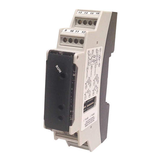
Thanks for choosing a Pixsys controller. The DRR460 series integrates in a single device the main elements of the control loop: reading of temperature sensor, control output by SSR module, reading and control of the current on the load by means of integrated current CT. -
Page 6: Precautions For Safe Use
A malfunction in the Digital Controller may occasionally make control operations impossible or prevent alarm outputs, resulting in property damage. To maintain Warning! safety in the event of malfunction of the Digital Controller, take appropriate safety measures, such as installing a monitoring device on a separate line. Precautions for safe use Be sure to observe the following precautions to prevent operation failure, malfunction, or adverse affects on the performance and functions of the product. -
Page 7: Model Identification
Model identification Power supply 24Vdc ±15% + 1 analogue input + 2 logic output 24Vdc/50mA DRR460-12A-T128 + 1 output 0/4...20mA + RS485 +C.T. Power supply 24Vdc ±15% + 1 analogue input + 2 logic output 24Vdc/50mA DRR460-12A-CAN + 1 output 0/4...20mA + CANopen +C.T. Technical data Main features Operating... -
Page 8: Dimensions And Installation
Attacco a guida DIN EN50022 Din rail mounting guide EN50022 Dimensions and Installation 64 mm 18 mm 13 14 15 16 9 10 11 12 5 6 7 8 1 2 3 4 Attacco a guida DIN EN50022 Din rail mounting guide EN50022 Electrical wirings This controller has been designed and manufactured in conformity to Low Voltage Directive 2014/35/ EU (LVD) and EMC Directive 2014/30/EU (EMC). -
Page 9: Analogue Input
Analogue Input 5.1.b For thermocouples K, S, R, J, T, E, N, B. • Comply with polarity • For possible extensions, use compensated cable and terminals suitable for the thermocouples used(compensated) – Shield / Schermo • When shielded cable is used, it should be grounded at one side only Shield / Schermo Rosso For thermoresistances PT100, Ni100. -
Page 10: Ct Input
CT input 5.1.e Input for CT 50mA. Sampling time 100 µs. Current measure true RMS for Heater Break Alarm and overcurrent alarm functions. Digital outputs 5.1.f 24VDC / 50mA – Digital output 24VDC ±15%/ 50mA 24VDC / 50mA – Analogue output 5.1.g inear output in mA (galvanically insulated from the sensor) configurable as 0/4..20mA... -
Page 11: Dip Switch
Dip switch DIP 1 – Slave address • If contacts 1..8 are OFF, modbus slave address is selected on parameter 111 sL.ad. • Determines modbus slave address, in binary code as indicated below: 00000001=1; 00000010=2; 00000011=3; 00000100=4; 00000101=5; 00000110=6; 00000111=7; 01111101=125; 01111110=126; 01111111=127; 10000000=128;... -
Page 12: Autotuning Launch "Once
AutoTuning Launch “Once” Set 3 on parameter 31 (word 2031). Autotuning procedure is executed only once at next DRR460 tune restart. If the procedure doesn’t work, will be executed at next restart. Synchronized tuning Select 4 on parameter 31 ( word 2031). -
Page 13: Dual Action Heating-Cooling
Dual Action Heating-Cooling DRR460 is suitable also for systems requiring a combined heating-cooling action.The command output has to be configured as PID for Heating (par. 33 greater than 0), while the alarm 1 and 2 has p.b. to be configured as Cooling (value 9 on par. 56 o par. -
Page 14: Soft-Start Function
The parameter has the same meaning as the heating time cycle co.c.t. t.c. Par. 41 (Cooling Fluid – word 2041) pre-selects the proportional band multiplier and the coo.F. p.b.m. cooling PID cycle time basing on the type of cooling fluid: co.c.t. -
Page 15: Expansion Function
7.13 Expansion function Selecting 1 on parameter 121 (“Expansion Module” word 2121) DRR460 works as a expansion E.Mod. module. Controller functions (temperature control, alarms, softstart etc..) are disabled and outputs management must be done by an external master (Es. PLC, HMI panel...). It is possible to confi gure output status at starting and in case of error, programming parameters 122...131 (parag. - Page 16 Modbus Read Reset Descrizione address Write value Slave address Eepr/dip Baud rate Eepr/dip Automatic addressing Installation code comparision for automatic learning of slave address Loading default values (write 9999) Restart DRR460 (write 9999) 1000 Process (tenth of degree) 1001 Command setpoint (tenth of degree) EEPROM 1002 Alarm 1 setpoint (tenth of degree)
- Page 17 Modbus Read Reset Descrizione address Write value 1013 Current CT (ampere with tenth) 1014 Current CT ON (ampere with tenth) 1015 Current CT OFF (ampere with tenth) 1016 Key status (0=rilasciato, 1=premuto) 1017 Dip 1 value 1100 Process (if temperature, no tenth) 1101 Command setpoint (if temperature, no tenth) EEPROM...
- Page 18 Modbus Read Reset Descrizione address Write value 1213 AO value by serial (Par.100 = 6) Error flags 1 Bit0 = Cold junction error Bit1 = Process error (sensor) Bit2 = Error in eeprom writing Bit3 = Error in eeprom reading Bit4 = Error missing calibration 1214 Bit5 = Generic error...
-
Page 19: Regulation Control
Modbus Read Reset Descrizione address Write value 1303 Latch on virtual zero calibration Serial process reset. Write 1 to disable the serial process. 1400 (process = AI1) 1401 Word serial process. AI1 is not considered 1500 Process (if temperature, with tenth) 1501 CT instantaneous current (ampere with tenth) 1502... -
Page 20: C 2 And 4 Advanced Burst Fire Control
2 and 4 Advanced Burst fire control For this type of control it is necessary to use a “Non zero-crossing” SSR. In order to minimise power fluctuation during the modulation period, the “advanced Burst fire” SSR output firing mode uses: ·... - Page 21 Lower Linear Input (Word modbus 2003) Lo.L. i . Range AN1 lower limit only for linear input. Ex: with input 4..20 mA this parameter takes value associated to 4 mA. -32767..+32767, Default: 0. Upper Linear Input (Word modbus 2004) up.L. i . Range AN1 upper limit only for linear input.
- Page 22 Group B - OUTPUT AND REGULATION Command Output (Word modbus 2016) c.out Command output type selection Command Q1; Alarm 1 Q2; Alarm 2 AO (0..20 mA). (Default) Command Q1; Alarm 1 Q2; Alarm 2 AO (4..20 mA). Valve command: Q1 (open) - Q2 (close); Alarm 1 AO (0..20 mA) Valve command: Q1 (open) - Q2 (close);...
- Page 23 Command Reset (Word modbus 2022) c. re. Type of reset for state of command contact (always automatic in P.I.D. functioning) Automatic reset (Default) Manual reset (by word 1029) Manual reset stored (keeps relay status also after an eventual power failure) Command Delay (Word modbus 2023) c.
- Page 24 Dead Band (Word modbus 2036) d.b. Dead Band. 0...10000 [digit] (degrees.tenths for temperature sensors) (Default: 0) Proportional Band Centered (Word modbus 2037) p.b.c. Defines if the proportional band has to be centered on setpoint. In double loop functioning (heating/cooling) is always disabled. Disabled.
- Page 25 Max Gap Tune (Word modbus 2047) m.G.tu. Selects the max. process-setpoint gap over that the automatic tuning recalculates PID parameters. 0-10000 [digit] (degrees.tenths for temperature sensors). Default: 30 Minimum Proportional Band (Word modbus 2048) mn.p.b. Selects the min. proportional band value selectable by the automatic tuning. 0-10000 [digit] (degrees.tenths for temperature sensors).
- Page 26 Alarm 1 State Output (Word modbus 2057) A.I .5.o Alarm 1 output contact and intervention type. (N.O. Start) Normally open, active at start (Default) (N.C. Start) Normally closed, active at start (N.O. Threshold) Normally open, active on reaching alarm 1 p. 33 (N.C.
- Page 27 Alarm 2 State Output (Word modbus 2069) A.2.5.o Alarm 2 output contact and intervention type. (N.O. Start) Normally open, active at start (Default) (N.C. Start) Normally closed, active at start (N.O. Threshold) Normally open, active on reaching alarm 1 p. 33 (N.C.
- Page 28 Soft-Start Threshold (Word modbus 2083) SS.tH. Threshold under which the device enables percentage soft-start function, at starting. -10000...10000 [digit] (degrees.tenths for temperature sensors) (Default: 1000) Soft-Start Time (Word modbus 2084) SS.ti. Max. softstart duration: if the process doesn’t reach the threshold entered on parameter 50 within the selected time, the controller will start to regulate on setpoint value.
- Page 29 101 re.ty. Retransmission Type (Word modbus 2101) Select the type of Retransmission 0...20 mA 4...20 mA (Default) 102 Lo.L.r. Lower Limit Retransmission (Word modbus 2102) Linear output lower limit range (value related to 0/4 mA) -32767..+32767 [digit] (degrees for temperature sensors), Default: 0. 103 up.L.r.
- Page 30 114 se.de. Serial Delay (Word modbus 2114) Selects the serial delay. 0...100 ms. Default: 0 ms. 115 off.L. Off Line (Word modbus 2115) Selects the off-line time. If no communication is available within the selected time, the controller will switch-off the command output. Offline disabled (Default) 1...6000 tenths of seconds (Es.
-
Page 31: Alarm Intervention Modes
129 E.M.A.o. Error Mode Analogue Output (Word modbus 2129) Defi nes if the analogue output has to commute to a default value in case of error or off -line. If the error is eliminated, the output keeps the default value AO unvaried in case of error (Default) AO commuted in case of error 130 E.v.A.o. -
Page 32: Band Alarm (Word 2056 = 3)
Band alarm (word 2056 = 3) 11.c Alarm Spv Alarm Spv Hysteresis parameter > 0 Band alarm hysteresis value greater than “0” (Par.58 > 0).* A. 1 .HY. Time Alarm output Hysteresis parameter < 0 Comand Spv Alarm Spv Alarm Spv Band alarm hysteresis value less than “0”... -
Page 33: Table Of Anomaly Signals
Table of Anomaly Signals If installation malfunctions, the controller switches off the regulation output and reports the anomaly noticed on word 1009 (error flags). For example, the controller will report a defective thermocouple by flashing alternately red/yellow LED and setting to 1 the bit 0 of the word 1009. For other signals see table below: Cause What to do... - Page 34 Table of configuration parameters GROUP A - ANALOGUE INPUT Sensor (Word modbus 2001) SEN. Degree (Word modbus 2002) deGr. Lower Linear Input (Word modbus 2003) Lo.L. i . Upper Linear Input (Word modbus 2004) up.L. i . Potentiometer Value (Word modbus 2005) Pot.v.
- Page 35 53÷55 Reserved Parameters - Group C GROUP D - ALARM 1 Alarm 1 (Word modbus 2056) AL. 1 Alarm 1 State Output (Word modbus 2057) A.I .5.o Alarm 1 Hysteresis (Word modbus 2058) a. 1 .Hy. Alarm 1 State Error (Word modbus 2059) a.
- Page 36 GROUP J - EXPANSION Expansion Module (Word modbus 2121) E.Mod. Initial Value Output (Word modbus 2122) i.vA.o. Error Mode Output (Word modbus 2123) E.Mo.o. Error Value Output (Word modbus 2124) E.vA.o. Analogue Output Type (Word modbus 2125) A.o.ty. Lower Limit Analogue Output (Word modbus 2126) L.L.A.o.
-
Page 37: Norme Di Sicurezza
Introduzione Grazie per aver scelto un regolatore Pixsys. La serie DRR460 integra in un unico dispositivo gli elementi fondamentali del loop di controllo: lettura della sonda di temperatura, controllo dell’uscita di regolazione analogica o digitale, lettura e controllo della corrente che passa attraverso il carico grazie all’ingresso per il trasformatore amperometrico. La comunicazione via seriale RS485 con protocollo Modbus Rtu o CANopen, consente la connessione a PC/terminali HMI per la supervisione ed il controllo a distanza. -
Page 38: Precauzioni Per L'uso Sicuro
Un malfunzionamento nel controllore digitale può occasionalmente rendere impossibili le operazioni di controllo o bloccare le uscite di allarme, con conseguenti Warning! danni materiali. Per mantenere la sicurezza, in caso di malfunzionamento, adottare misure di sicurezza appropriate; ad esempio con l’installazione di un dispositivo di monitoraggio indipendente e su una linea separata. -
Page 39: Identificazione Del Modello
Identificazione del modello Alim. 24Vdc ±15% + 1 ingr. analogico + 2 uscite logiche 24Vdc/50ma + 1 DRR460-12A-T128 uscita 0/4...20mA + Rs485 +C.T. Alim. 24Vdc ±15% + 1 ingr. analogico + 2 uscite logiche 24Vdc/50ma + 1 DRR460-12A-CAN uscita 0/4...20mA + CANopen +C.T. Dati tecnici Caratteristiche generali Condizioni operative Temperatura: 0-45°C;... -
Page 40: Dimensioni Ed Installazione
Attacco a guida DIN EN50022 Din rail mounting guide EN50022 Dimensioni ed installazione 64 mm 18 mm 13 14 15 16 9 10 11 12 5 6 7 8 1 2 3 4 Attacco a guida DIN EN50022 Din rail mounting guide EN50022 Collegamenti elettrici Questo regolatore è... -
Page 41: Ingresso Analogico
Ingresso analogico 5.1.b Per termocoppie K, S, R, J, T, E, N, B. • Rispettare la polarità • Per eventuali prolunghe utilizzare cavo compensato e morsetti adatti alla termocoppia utilizzata (compensati) – • Quando si usa il cavo schermato, la schermatura va collegata a terra ad Shield / Schermo una sola estremità... -
Page 42: Ingresso Per Trasformatore Amperometrico
Ingresso per trasformatore amperometrico 5.1.e Ingresso per trasformatore amperometrico 50mA. Tempo si campionamento 100 µs. Misura corrente true RMS per funzioni di Heater Break Alarm e allarme di sovracorrente. Uscite digitali 5.1.f 24VDC / 50mA – Uscita digitale 24VDC ±15%/ 50mA 24VDC / 50mA –... -
Page 43: Dip Switch
Dip switch DIP 1 - Indirizzo slave • Se i contatti 1..8 sono in posizione OFF l’indirizzo slave per il modbus impostato sul parametro 111 sL.ad. • Determina l’indirizzo slave per il modbus, in codice binario come indicato nel seguente esempio: 00000001=1;... -
Page 44: Lancio Dell'autotuning "Once
Lancio dell’AutoTuning “Once” Impostare 3 sul parametro 31 (word 2031). La procedura di autotuning viene eseguita solo una tune volta alla successiva riaccensione del DRR460. Se per qualsiasi motivo la procedura non dovesse andare a buon fine, verrà eseguita alla successiva riaccensione. Tuning “sincronizzato”... -
Page 45: Funzionamento In Doppia Azione (Caldo-Freddo)
seconti il tasto . • Impostare sul parametro 94 il tempo di ritardo in secondi per l’intervento dell’ Heater Break H.b.a.d. Alarm. • È possibile associare un allarme, impostando 10 sul parametro 56 o parametro 68 aL. 1 aL. 2 È... -
Page 46: Funzione Soft-Start
ACTIVE ALARM OUTPUT (COOL) x = COOL > 0 (HEAT) ACTIVE COMMAND OUTPUT (HEAT) ACTIVE ALARM OUTPUT (COOL) Il par. ha lo stesso significato del tempo di ciclo per l’azione caldo. co.t.c. Il par. 41 (Cooling Fluid – word 2041) pre-seleziona il moltiplicatore di banda proporzionale coo.F. -
Page 47: Funzione Espansione
Word Eff etto Eseguire Scrivere 1 per abilitare la procedura di Latch Posizionare il sensore sul valore minimo di 1300 on. Scrivendo 0 la procedura termina. funzionamento (associato a Lo.L. i . Posizionare il sensore sul valore massimo di 1301 Scrivere 1 per fi ssare il valore sul minimo. - Page 48 Modbus RTU protocol features Selezionabile da parametro 113 s.p.p. Valore 0: 8N1 Valore 3: 8N2 Formato Valore 1: 8E1 Valore 4: 8E2 Valore 2: 8O1 Valore 5: 8O2 WORD READING (max 20 word) (0x03, 0x04) Funzioni SINGLE WORD WRITING (0x06) supportate MULTIPLE WORDS WRITING (max 20 word) (0x10) Si riporta di seguito l’elenco di tutti gli indirizzi disponibili e le funzioni supportate:...
- Page 49 Modbus Read Reset Descrizione address Write value Stato allarmi (0=assente, 1=presente) 1008 Bit0 = Allarme 1 Bit1 = Allarme 2 Flags errori 1 Bit0 = Errore giunto freddo Bit1 = Errore processo (sonda) Bit2 = Errore scrittura eeprom Bit3 = Errore lettura eeprom Bit4 = Errore tarature mancanti 1009 Bit5 = Errore generico...
- Page 50 Modbus Read Reset Descrizione address Write value Con Tune automatico (word 2005 = 1): 0=funzione autotuning OFF 1=autotuning in corso Con Tune manuale (word 2005 = 2): 0=funzione autotuning OFF 1=autotuning ON 1205 Con Tune sincronizzato (word 2005 = 3): 0=funzione autotuning OFF 1=uscita di comando spenta (forza il raffreddamento) 2=uscita di comando accesa (forza il riscaldamento)
- Page 51 Modbus Read Reset Descrizione address Write value Percentuale uscita comando (0-1000) 1218 Percentuale uscita caldo in doppio loop 1219 Percentuale uscita freddo in doppio loop (0-1000) Percentuale uscita comando (0-100) 1220 Percentuale uscita caldo in doppio loop 1221 Percentuale uscita freddo in doppio loop (0-100) 1222 Corrente CT istantanea (ampere con decimo) 1223...
-
Page 52: Controllo Di Regolazione
Controllo di regolazione Il DRR460 integra diversi tipi di controllo per la regolazione dell’uscita di comando, selezionando il parametro 52 come segue: o.cL.t. 0 Controllo a tempo Per questo tipo di controllo è consigliato usare un SSR “zero-crossing”. L’attivazione e lo spegnimento dell’uscita avviene in base al tempo impostato sul parametro 40 c.t. -
Page 53: Tabella Parametri Di Configurazione
Tabella parametri di configurazione GRUPPO A - INGRESSO ANALOGICO Sensor (Word modbus 2001) SEN. Configurazione ingresso analogico/selezione sensore Tc-K -260 °C..1360 °C. (Default) Tc-S -40 °C..1760 °C Tc-R -40 °C..1760 °C Tc-J -200 °C..1200 °C Tc-T -260 °C..400 °C Tc-E -260 °C..980 °C Tc-N -260 °C..1280 °C... - Page 54 Gain Calibration (Word modbus 2008) G.caL. Calibrazione guadagno. Valore che si moltiplica al processo per eseguire calibrazione sul punto di lavoro. Es: per correggere la scala di lavoro da 0..1000°C che visualizza 0..1010°C, fissare il parametro a -1.0 -1000 (100.0%)...+1000 (+100.0%), Default: 0.0. Latch-On (Word modbus 2009) Ltch Impostazioen automatica dei limiti per ingresso lineare...
- Page 55 Command State Error (Word modbus 2020) c. S.e. Stato del contatto per l’uscita di comando in caso di errore 0 mA se comando su AO. Contatto aperto se comando su Q1. Valvola aperta se comando valvola. Default 4 mA se comando su AO. Contatto chiuso se comando su Q1. Valvola chiusa se comando valvola.
- Page 56 GRUPPO C - AUTOTUNING E P.I.D. Tune (Word modbus 2031) tune. Selezione il tipo di autotuning Disabilitato (Default) Automatico (P.I.D. con calcolo dei parametri automatico) Manuale (P.I.D. con calcolo parametri automatico lanciato dalla word 1004 o 1205) Once (P.I.D. con calcolo dei parametri solo una volta alla riaccensione) Tuning sincronizzato.
- Page 57 Cooling Fluid (Word modbus 2041) coo.F Tipo di fluido refrigerante in modalità P.I.D. caldo / freddo. Abilitare l’uscita freddo nel parametro AL.1 o AL.2. Aria (Default) Olio Acqua Proportional Band Multiplier (Word modbus 2042) P.b.M. Moltiplicatore di banda proporzionale. La banda proporzionale per l’azione freddo è data dal valore del par.
- Page 58 Overshoot Control Level 1 o.c.L. 1 La funzione di controllo dell’overshoot previene tale fenomeno all’accensione dello strumento o quando il setpoint viene modificato. Impostando un valore troppo basso è possibile che l’overshoot non venga completamente assorbito, mentre con valori alti il processo potrebbe raggiungere il setpoint più...
- Page 59 Alarm 1 State Stop (Word modbus 2060) a. 1 .s.S. Stato del contatto per l’uscita di allarme 1 con regolatore in STOP 0 mA se allarme 1 su AO. Contatto aperto se allarme 1 su Q1 o Q2. Default 4 mA se allarme 1 su AO. Contatto chiuso se allarme 1 su Q1 o Q2. 20 mA se allarme 1 su AO.
- Page 60 Alarm 2 State Error (Word modbus 2071) a.2.s.e. Stato del contatto per l’uscita di allarme 2 in caso di errore 0 mA se allarme 1 su AO. Contatto aperto se allarme 2 su Q2. Default 4 mA se allarme 1 su AO. Contatto chiuso se allarme 2 su Q2 20 mA se allarme 2 su AO.
- Page 61 85÷89 Reserved Parameters - Group F Parametri riservati - Gruppo F GRUPPO G - CURRENT TRANSFORMER Current Transformer (Word modbus 2090) c.t. Abilita il funzionamento dell’ingresso C.T. e seleziona la frequenza di rete Disabilitato (Default) 50 Hz 60 Hz Current Transformer Value (Word modbus 2091) c.t.
- Page 62 104 re.s.e. Retransmission State Error (Word modbus 2104) Determina il valore dell’uscita analogica in caso di errore o anomalia 0 mA (Default) 4 mA 20 mA 21.5 mA 105 re.s.S. Retransmission State Stop (Word modbus 2105) Determina il valore dell’uscita analogica con regolatore in STOP 0 mA (Default) 4 mA 20 mA...
- Page 63 GRUPPO J - ESPANSIONE 121 E.Mod. Expansion Module (Word modbus 2121) Abilita la modalita “Modulo di espansione”. Disabled (Default) Enabled 122 i.vA.o. Initial Value Output (Word modbus 2122) Seleziona lo stato delle uscite all’accensione. Bit 0 Q1 (0 = off; 1 = on) Default: 0 Bit 1 Q2 (0 = off;...
-
Page 64: Modi D'intervento Allarme
Modi d’intervento allarme Allarme assoluto o allarme di soglia attivo sopra (word 2056 = 1) 11.a Alarm Spv Hysteresis parameter > 0 Allarme assoluto. Valore di isteresi maggiore di “0” (Par. 58 > 0). a. 1 .HY Time Alarm output Hysteresis parameter... -
Page 65: Allarme Di Deviazione Superiore (Word 2056 = 4)
Allarme di deviazione superiore (word 2056 = 4) 11.d Alarm Spv Alarm Spv Allarme di deviazione superiore valore di setpoint allarme maggiore Hysteresis parameter > 0 di “0” e valore di isteresi maggiore di “0” (Par. 58 > 0). a. - Page 66 Note / Aggiornamenti 1. All’accensione, l’uscita è inibita se lo strumento è in condizione di allarme. Si attiva solo quando rientrato dalla condizione d’allarme, questa si ripresenta. - DRR460 - Manuale d’uso...
- Page 67 Manuale d’uso - DRR460 -...
- Page 68 Tabella delle configurazioni dei parametri GRUPPO A - INGRESSO ANALOGICO Sensor (Word modbus 2001) SEN. Degree (Word modbus 2002) deGr. Lower Linear Input (Word modbus 2003) Lo.L. i . Upper Linear Input (Word modbus 2004) up.L. i . Potentiometer Value (Word modbus 2005) Pot.v.
- Page 69 53÷55 Reserved Parameters - Group C GRUPPO D - ALLARME 1 Alarm 1 (Word modbus 2056) AL. 1 Alarm 1 State Output (Word modbus 2057) A.I .5.o Alarm 1 Hysteresis (Word modbus 2058) a. 1 .Hy. Alarm 1 State Error (Word modbus 2059) a.
- Page 70 GRUPPO J - ESPANSIONE Expansion Module (Word modbus 2121) E.Mod. Initial Value Output (Word modbus 2122) i.vA.o. Error Mode Output (Word modbus 2123) E.Mo.o. Error Value Output (Word modbus 2124) E.vA.o. Analogue Output Type (Word modbus 2125) A.o.ty. Lower Limit Analogue Output (Word modbus 2126) L.L.A.o.
- Page 72 Prima di utilizzare il dispositivo leggere con attenzione le informazioni di sicurezza e settaggio contenute in questo manuale. Prog. Cntlr E498498 PIXSYS s.r.l. www.pixsys.net sales@pixsys.net - support@pixsys.net online assistance: http://forum.pixsys.net via Po, 16 I-30030 Mellaredo di Pianiga, VENEZIA (IT) Tel +39 041 5190518 2300.10.252-RevC...
Need help?
Do you have a question about the DRR460 Series and is the answer not in the manual?
Questions and answers