Table of Contents
Advertisement
Available languages
Available languages
Quick Links
Advertisement
Table of Contents

Related Manuals for Pixsys DRR227


Summary of Contents for Pixsys DRR227
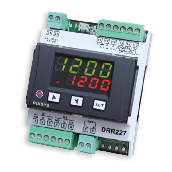
- Page 1 DRR227 Controller / Regolatore User manual / Manuale d’uso...
-
Page 3: Table Of Contents
8.1 Loading default values ........................15 9 Table of Configuration Parameters ....................... 16 10 Alarm Intervention Modes ........................24 11 Table of Anomaly Signals......................... 26 12 Configuration EASY-UP ..........................27 13 Summary of Configuration parameters ....................27 User manual - DRR227 -... - Page 4 8 Accesso alla configurazione ........................40 8.1 Caricamento valori di default ......................41 9 Tabella parametri di configurazione .....................41 10 Modi d’intervento allarme ........................49 11 Tabella segnalazioni anomalie ......................52 12 Configurazione EASY-UP .......................... 52 13 Promemoria configurazione ........................53 - DRR227 - Manuale d’uso...
-
Page 5: Safety Guide Lines
Introduction Thank you for choosing a Pixsys controller. With the DRR227 Pixsys model Pixsys makes available in a single device multiple options related to sensor input and actuators command in addition to the extended power range 24..230 Vac/Vdc. With the various selectable sensors and the output con-... -
Page 6: Hardware Features
0..9999 °C o °F Integral time 0,0..999,9 sec. (0 excluded Derivative time 0,0..999,9 sec. (0 excluded Manual or automatic Tuning, selectable alarm, protection of Controller functions command and alarm setpoints, activation of functions via digital input - DRR227 - User manual... -
Page 7: Dimensions And Installation
Extractable terminal blocks Electrical wirings Although this controller was designed to resist electromagnetic interferences in industrial environments, please observe following safety guidelines: • Separate the control line from the power wires. • Avoid proximity of remote control switches, electromagnetic contactors, powerful engines and in all instances use specific filters. • Avoid proximity of power groups, especially those with phase control. User manual - DRR227 -... -
Page 8: Wiring Diagram
For linear signals in Volt and mA +Vdc = 12Vdc ±15%/ 30mA Comply with polarity When shielded cable is used, it should be grounded at one +Vdc 30 mA side only to avoid ground loop currents - DRR227 - User manual... - Page 9 AC125V COS ø=0.4 Electrical endurance Q1 / Q2. DC30 V t=7ms 5A, 250 Vac, resistive load, 10 operations 20/2 A, 250 Vac, cosφ = 0.3, 10 operations AC250V COS ø=0.4 DC30 V t=15ms Contact load current (A) User manual - DRR227 -...
-
Page 10: Display And Keys Functions
ON when the output command is on A1 A2 ON when the corresponding alarm is active ON when the “Manual” function is on ON when the controller is running an “Autotuning” cycle ON when the controller communicates via serial port (USB) - DRR227 - User manual... -
Page 11: Keys
• Running Tuning by digital input: Select tunE on parameter 25 dGt. i . At first activation of digital input (commutation on TUN led front panel) switches ON while at second activation switches off. User manual - DRR227 -... -
Page 12: Automatic Tuning
• run. : Regulation is enabled only with digital input active; • tune : Enables/disables Tuning, if parameter 8 P. i .d. is set on man. ; • au.ma. : (Automatic/Manual) if par. 19 au.ma. is set on en. or en.st. , DRR227 regulates in - DRR227 - User manual... -
Page 13: Memory Card (Optional)
Enter configuration (password 1234): Exiting configuration mode, the settings will be automatically saved on Memory card. 7.9 Regulation control DRR227 integrates different types of control for the regulation of the SSR command output, selecting parameter 43 o.cL.t. as follows: Time control... - Page 14 Phase angle control PHs.A. If this mode is active, the regulation is done through the phase choking 25% Power Using a no zero-crossing SSR, the DRR227 synchronizes with the power supply volage 50% Power (necessarily AC) and determines when 75% Power...
-
Page 15: Configuration
1st digit flashing, while for 3 sec display 2 shows PASS Modify the flashing digit and move to the next one Enter password 9999 pressing The device loads default Turn off and restart the settings device to confirm User manual - DRR227 -... -
Page 16: Table Of Configuration Parameters
Decimal Point (Password 1234) d.P. Select number of displayed decimal points No displayed decimal Default 1 decimal 2 decimals 0.00 3 decimals 0.000 Degree (Password 1234) deGr. Select degree type Celsius (Default) c Fahrenheit f - DRR227 - User manual... - Page 17 ] (degrees.tenths for temperature sensors), Default: 1750. Offset Calibration (Password 5678) o.cAL. Value added/subtracted to the process value (ex: usually correcting the ambient temperature value). -999..+1000 [digit ] for linear sensors and potentiometers. -200.0..+100.0 (degrees.tenths for temperature sensors), Default 0.0. User manual - DRR227 -...
- Page 18 Command delay (only in ON / OFF functioning). -900..+900 seconds.. Default: 0. Negative: delay in switching off phase. Positive: delay in activation phase. Automatic / Manual (Password 1234) au.ma. Enables automatic/manual selection. Disabled (Default) dis. Enabled Enabled stored En.St. - DRR227 - User manual...
- Page 19 (N.C. Threshold) Normally closed, active on reaching alarm n.c. t. On activation, the output is inhibited if the controller is in alarm mode. Activates only if alarm condition reappers, after that it was restored.. User manual - DRR227 -...
- Page 20 Positive: delay in alarm entry phase. Alarm 2 (Password 1234) AL.2 Alarm 2 selection. Disabled (Default) dis. Absolute / threshold, referring to process A. AL. Band alarm b. AL. Upper deviation alarm H.d.AL. Lower deviation alarm L.d.AL. - DRR227 - User manual...
- Page 21 Negative: delay in alarm output phase Positive: delay in alarm entry phase. On activation, the output is inhibited if the controller is in alarm mode. Activates only if alarm condition reappers, after that it was restored. User manual - DRR227 -...
- Page 22 0.0-999.9 seconds (0 = integral disabled), Default 0.0 Derivative Time (Password 5678) d.t. Normally ¼ of integral time. 0.0-999.9 seconds (0 = derivative disabled), Default 0.0 Dead Band (Password 5678) d.b. 0-1000 [digit1] (degrees.tenths for temperature sensors) (Default: 0) - DRR227 - User manual...
- Page 23 Selects the max. proportional band value selectable by the automatic tune. 0.0..300.0°C/°F. Default: 50.0°C Minimum Integral Time (Password 5678) mn.i.t. Selects the min. integral time value selectable by the automatic tune. 0.0..999.9 secondi. Default: 40.0s. User manual - DRR227 -...
-
Page 24: Alarm Intervention Modes
Alarm output Time Absolute alarm with controller in cooling Alarm Spv functioning Hysteresis (Par.7 Act.t. selected ooL ) and hysteresis parameter < 0 value less than “0”(Par.29 A. 1 .HY. < 0).* Alarm output - DRR227 - User manual... - Page 25 Alarm Spv Alarm Spv Alarm Spv Upper deviation alarm value of alarm Hysteresis setpoint less than “0” and hysteresis parameter > 0 value greater than “0” (Par.29 A. 1 .HY. > 0).** Time Alarm output User manual - DRR227 -...
-
Page 26: Table Of Anomaly Signals
Check if the confi guration parame- Possible loss of calibration values ters are correct EEP.E E-05 Thermocouple open or temperature Check the connection with the outside of limits sensors and their integrity prb. E-08 Missing calibration data Call Assistance SYS.E - DRR227 - User manual... -
Page 27: Configuration Easy-Up
Configuration EASY-UP To simplify the setting of parameters and the integration of the different components involved in the control system, Pixsys introduces the EASY-UP coding which allows to set sensors and/or command outputs in one single step. By means of the code listed in the data sheet enclosed to the sensor or actuator (SSR, motorized valve, etc.) the EASY-UP coding will set the relevant main parameters on... - Page 28 Upper Limit Phase Angle Percentage (Password 5678) u.L.P.P. Proportional Band (Password 5678) p.b. Integral Time (Password 5678) i.t. Derivative Time (Password 5678) d.t. Dead Band (Password 5678) d.b. Cycle Time (Password 5678) c.t. Lower Limit Output Percentage (Password 5678) L.L.o.P. - DRR227 - User manual...
- Page 29 Upper Limit Output Percentage (Password 5678) U.L.o.p. Setpoint Deviation Tune (Password 5678) s.d.tu. Max Gap Tune (Password 5678) m.G.tu. Minimum Proportional Band (Password 5678) mn.p.b. Maximum Proportional Band (Password 5678) ma.p.b. Minimum Integral Time (Password 5678) mn.i.t. Notes / Updates User manual - DRR227 -...
-
Page 30: Norme Di Sicurezza
Introduzione Grazie per aver scelto un regolatore Pixsys. Con il modello DRR227 Pixsys rende disponibile in un singolo strumento tutte le opzioni relative alla connessione dei sensori e al comando di attuatori, con in aggiunta un’utile alimentazione a range esteso da 24..230 Vac/Vdc. Con le molteplici sonde selezionabili e l’uscita configurabile come relè... -
Page 31: Caratteristiche Hardware
Tempo integrale 0,0..999,9 sec. (0 esclude funzione integrale) Tempo derivativo 0,0..999,9 sec. (0 esclude funzione derivativa) Funzioni del Tuning manuale o automatico allarme selezionabile, protezione regolatore set comando e allarme, selezione funzioni da ingresso digitale Manuale d’uso - DRR227 -... -
Page 32: Dimensioni Ed Installazione
è buona norma seguire la seguenti precauzioni: • Distinguere la linea di alimentazioni da quelle di potenza. • Evitare la vicinanza di gruppi di teleruttori, contattori elettromagnetici, motori di grossa potenza e comunque usare gli appositi filtri. • Evitare la vicinanza di gruppi di potenza, in particolare se a controllo di fase. - DRR227 - Manuale d’uso... -
Page 33: Schema Di Collegamento
Shield/Schermo Per segnali normalizzati in corrente e tensione. +Vdc = 12Vdc ±15%/ 30mA Rispettare la polarità. Quando si usa il cavo schermato, la schermatura va collegata +Vdc 30 mA a terra ad una sola estremità Manuale d’uso - DRR227 -... - Page 34 NB: vedi grafico qui sotto Life Curve AC250V DC30 V AC125 V AC125V COS ø=0.4 Portata contatti: DC30 V t=7ms • 5A, 250Vac, carico resistivo, 10 operazioni. • 20/2A, 250Vac, cosφ=0.3, 10 operazioni. AC250V COS ø=0.4 DC30 V t=15ms Contact load current (A) - DRR227 - Manuale d’uso...
-
Page 35: Funzione Dei Visualizzatori E Tasti
A1 A2 Si accendono quando l’allarme corrispondente è attivo Si accende all’attivazione della funzione “Manuale” Si accende quando il regolatore sta eseguendo un ciclo di AutoTuning Si accende quando il regolatore comunica via seriale (USB) Manuale d’uso - DRR227 -... -
Page 36: Tasti
Il led TUN si accende e la procedura ha inizio. • Lancio del Tuning da ingresso digitale: Selezionare tunE su parametro 25 dGt. i . Alla prima attivazione dell’ingresso digitale (commutazione su fronte) il led TUN si accende, alla seconda si spegne. - DRR227 - Manuale d’uso... -
Page 37: Lancio Del Tuning Automatico
PID subito prima della rottura. Es: su un estrusore viene mantenuto il comando in percentuale della resistenza (carico) anche nel caso di guasto sulla sonda in ingresso. Manuale d’uso - DRR227 -... -
Page 38: Funzioni Da Ingresso Digitale
• tune : Abilita/disabilita il Tuning se il parametro 8 P. i .d. è impostato su man. ; • au.ma. : Se par. 19 au.ma. è impostato su en. o en.st. il DRR227 regola in manuale con ingresso digitale attivo, altrimenti la regolazione è di tipo automatico. - Page 39 · L’accensione avviene sinusoidi complete Per applicazioni con infrarossi ad onde corte il “Burst fire avanzato” diminuisce la luminosità degli elementi e quindi riduce al minimo il fastidioso sfarfallio visivo. Manuale d’uso - DRR227 -...
-
Page 40: Accesso Alla Configurazione
Phase angle control PHs.A. La regolazione, in questa modalità, avviene attraverso la parzializzazione di fase 25% Power Usando un SSR no zero-crossing il DRR227 si sincronizza con la tensione di alimentazione 50% Power (necessariamente AC) e determina quando 75% Power attivare l’uscita per creare la giusta parzializ-... -
Page 41: Caricamento Valori Di Default
-50 °C..150 °C Pt500 -100 °C..600 °C Pt1000 -100 °C..600 °C Pt1k 0..10 V 0-10 0..20 mA 0-20 4..20 mA 4-20 0..60 mV 0-60 Potenziometri fino a 6 kOhm Pot. 1 Potenziometri fino a 150 kOhm Pot.2 Manuale d’uso - DRR227 -... - Page 42 Once (PID con calcolo dei parametri solo una volta alla riaccensione) once Manuale (PID con calcolo automatico dei parametri lanciato da tastiera) Man. Lower Limit Setpoint (Password 1234) Lo.L.S. Limite inferiore impostabile per il setpoint ] (gradi per sensori di temperatura), Default: 0. -999..+9999 [digit - DRR227 - Manuale d’uso...
- Page 43 Tipo di riarmo del contatto di comando (sempre automatico in funzionamento PID) Riarmo automatico (Default) are. Reset manuale mre. Reset manuale memorizzato (mantiene lo stato del relè anche dopo un mre.s. eventuale mancanza di alimentazione) Manuale d’uso - DRR227 -...
- Page 44 Output reset (ingresso digitale impulsivo) o.rSt Digital Input Contact Type (Password 1234) d.i.c.t. Seleziona il contatto a riposo dell’ingresso digitale Contatto aperto (Default) o.c. Contatto chiuso c.c. Alarm 1 (Password 1234) AL. 1 Selezione allarme 1. Disabilitato (Default) dis. - DRR227 - Manuale d’uso...
- Page 45 Reset Manuale memorizzato (mantiene lo stato del relè anche dopo un mre.s. eventuale mancanza di alimentazione) All’accensione, l’uscita è inibita se lo strumento è in condizione di allarme. Si attiva solo quando rientrato dalla condizione d’allarme, questa si ripresenta. Manuale d’uso - DRR227 -...
- Page 46 Protezione set allarme 2. Non consente all’utente di variare il setpoint Modificabile dall’utente (Default) free Protetto Lock Protetto e non visualizzato Hide All’accensione, l’uscita è inibita se lo strumento è in condizione di allarme. Si attiva solo quando rientrato dalla condizione d’allarme, questa si ripresenta. - DRR227 - Manuale d’uso...
- Page 47 Seleziona il valore minimo per la percentuale dell’uscita di comando con controllo Phase Angle 0..40%, Default: 10%. Upper Limit Phase Angle Percentage (Password 5678) u.L.P.P. Seleziona il valore massimo per la percentuale dell’uscita di comando con controllo Phase Angle 60..100%, Default: 90%. Manuale d’uso - DRR227 -...
- Page 48 Imposta la deviazione dal setpoint di comando come soglia usata dall’ autotuning, per il calcolo dei parametri PID 0.0-500.0°C/°F. Default: 30.0. Max Gap Tune (Password 5678) m.G.tu. Imposta lo scostamento massimo processo-setpoint oltre il quale il tune automatico ricalcola i parametri PID 0.1..50.0°C/°F. Default: 1.0°C - DRR227 - Manuale d’uso...
-
Page 49: Modi D'intervento Allarme
Hysteresis Allarme assoluto con regolatore in funziona- parameter > 0 mento freddo Alarm Spv (Par.7 Act.t. selezionato ooL ) e valore di isteresi maggiore di “0” (Par.29 A. 1 .HY. > 0).* Alarm output Manuale d’uso - DRR227 -... - Page 50 Allarme di deviazione superiore valore di > 0 Comand Spv Comand Spv setpoint allarme maggiore di “0” e valore di isteresi maggiore di “0” (Par.29 A. 1 .HY. > 0).** Time Alarm output - DRR227 - Manuale d’uso...
- Page 51 ** a) L’esempio è riferito all’allarme 1; la funzione è abilitabile anche per l’allarme 2 .b) Con isteresi minore di “0” ( < 0) la linea tratteggiata si sposta sopra il Setpoint di allarme. A. 1 .HY. Manuale d’uso - DRR227 -...
-
Page 52: Tabella Segnalazioni Anomalie
Configurazione EASY-UP Per semplificare il più possibile il lavoro di parametrizzazione della catena di controllo, Pixsys presenta una nuova modalità a codici che consente di configurare con un unico e semplice passaggio ingressi sonda e/o uscite di comando. La modalità EASY-UP tramite il codice presente sulla documentazione tecnica allegata al sensore o all’attuatore (SSR, valvola-motorizzata, ecc..) configura sullo strumento... -
Page 53: Promemoria Configurazione
AL. 1 Alarm 1 State Output (Password 1234) A.I .5.o Alarm 1 Hysteresis (Password 1234) a. 1 .Hy. Alarm 1 Led (Password 5678) a. 1 .Ld. Alarm 1 State Error (Password 5678) a. 1 .s.e. Manuale d’uso - DRR227 -... - Page 54 Upper Limit Output Percentage (Password 5678) U.L.o.p. Setpoint Deviation Tune (Password 5678) s.d.tu. Max Gap Tune (Password 5678) m.G.tu. Minimum Proportional Band (Password 5678) mn.p.b. Maximum Proportional Band (Password 5678) ma.p.b. Minimum Integral Time (Password 5678) mn.i.t. Note / Aggiornamenti - DRR227 - Manuale d’uso...
- Page 56 Read carefully the safety guidelines and programming instructions contained in this manual before using/connecting the device. Prima di utilizzare il dispositivo, leggere con attenzione le informazioni di sicurezza e settaggio contenute in questo manuale. PIXSYS s.r.l. www.pixsys.net sales@pixsys.net - support@pixsys.net online assistance: http://forum.pixsys.net 2300.10.220-RevA Software Rev. 1.07 141014...
Need help?
Do you have a question about the DRR227 and is the answer not in the manual?
Questions and answers