
Subscribe to Our Youtube Channel
Related Manuals for THORLABS LNR502E


Summary of Contents for THORLABS LNR502E
- Page 1 LNR502E(/M) Encoded, Long-travel Translation Stage with Stepper Motor Actuator User Guide Original Instructions HA0405T...
-
Page 2: Table Of Contents
LNR502E Encoded Long Travel, Linear Stage with Stepper Motor Actuator Contents Chaper 1 Overview ..........................1 1.1 Linear Long-travel Translation Stage ................1 Chaper 2 Safety ............................4 2.1 Safety Information ......................4 2.2 General Warnings ......................4 Chaper 3 Installation ..........................5 3.1 Unpacking .......................... -
Page 3: Linear Long-Travel Translation Stage
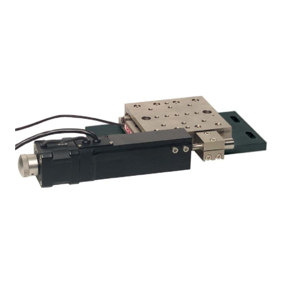
Combining the TravelMax stage with an integrated optical encoder provides the ideal solution for when stability, long travel and high load capacity need to be coupled with absolute position accuracy. The TravelMax LNR502E features a sub-micron resolution position linear scale that is attached to the moving platform of the stage. The encoder reads this scale to provide the feedback to ensure true nanopositioning capabilities. - Page 4 1.1.2 Drives The stage is shipped complete with our DRV250 trapezoidal stepper motor drive. The piezo drives and manual drives advertised on our web site for use with the LNR50 stage are not compatible with the LNR502E encoded stage version. Note The DRV250 trapezoidal stepper motor drive must be used in conjunction with the BSC2xx series stepper motor controller and Kinesis software application.
-
Page 5: Safety Information
Chapter 2 Safety Chapter 2 Safety 2.1 Safety Information For the continuing safety of the operators of this equipment, and the protection of the equipment itself, the operator should take note of the Warnings, Cautions and Notes throughout this handbook and, where visible, on the product itself. The following safety symbols may be used throughout the handbook and on the equipment itself. -
Page 6: Unpacking
3.3.1 General The LNR502E series stages are mounted to the work surface as shown using a base plate. For additional versatility, an angle bracket is available for use in vertical mounting configurations - see Section 3.3.4. When mounting the stage close to other equipment, ensure that the travel of the moving platform is not obstructed. - Page 7 Chapter 3 Installation 3.3.2 Mounting to the Work Surface Referring to Fig. 3.1, proceed as follows: 1) Turn the motor knob to position the moving carriage central in its range of travel, and ensure that the mounting holes in the base are clearly visible through the holes in the top plate.
- Page 8 LNR502E Encoded Long Travel, Linear Stage with Stepper Motor Actuator 3.3.3 Building an XY Configuration Bolt the X-axis stage to the work surface as detailed in Section 3.3.2. then, referring to Fig. 3.2, proceed as follows: 1) Fit the dowels supplied to the moving platform of the lower stage.
- Page 9 Chapter 3 Installation Fig. 3.3 Fitting the Y-Axis Stage Rev A Apr 2020 Page 7...
- Page 10 LNR502E Encoded Long Travel, Linear Stage with Stepper Motor Actuator 3.3.4 Building an XYZ Configuration Assemble an XY configuration as detailed in Section 3.3.3. then, referring to Fig. 3.4, and Fig. 3.5 proceed as follows: 1) Fit the dowels supplied, into the moving platform on the upper stage of the XY assembly.
-
Page 11: Fitting And Removal Of Drives
Chapter 3 Installation 6) Fit two bolts (M6 x 12 or 1/4-20 x 1/2”, not supplied), through the holes in the top plate, and screw into the rear face of the angle bracket. Caution Use only bolts of the stated length. Longer bolts will protude into the stage and damage the internal mechanism. Fig. -
Page 12: Reconfiguring The Actuator Position
LNR502E Encoded Long Travel, Linear Stage with Stepper Motor Actuator 3.5 Reconfiguring the Actuator Position The stage is shipped with the drives configured for a right handed configuration, however they can be repositioned for left handed use. This is achieved by swapping the position of the actuator clamp and the push block as follows: Referring to Fig. - Page 13 Chapter 3 Installation 3) Using the splitter lead supplied, connect the stage to the Controller unit and SmartSignal module as shown in Fig. 3.9. 15 pin D1.5 D-Type Female - long lead To stepper motor connector 15 pin D1.5 D-Type Female - short lead To SmartSignal Electronics module 15 pin D-Type Male To MOTOR DRIVE on...
-
Page 14: Encoder Calibration Check
MicroE Systems. When the TravelMax is driven by a Thorlabs stepper motor actuator, all programmable and diagnostic features are enabled via the APT server software, and the following procedures assume that a Thorlabs DRV014 actuator is fitted (i.e. as shipped with the LNR502E). - Page 15 5) On start-up, the 'Actuator/Startup Settings' window is displayed. This window allows the correct actuator to be selected. Fig. 4.2 Select Actuator Settings Window - 1 6) Click the arrow on the right hand side of the drop down box and select LNR502E from the list displayed. Fig. 4.3 Select Actuator Settings Window - 2 7) Click OK.
- Page 16 LNR502E Encoded Long Travel, Linear Stage with Stepper Motor Actuator 2) Select the Advanced tab. Fig. 4.5 Settings - Advanced tab 3) In the PID Loop Mode field, select Closed Loop. 4) Encoder feedback is now enabled. When Closed Loop is selected, the motion processor within the controller uses a position control loop to determine the motor command output.
-
Page 17: Mounting Equipment To The Stage
Do not apply excessive forces to the moving platform. Thorlabs manufacture a variety of fibre chucks, holders and fixtures to fit the linear stage. All of these accessories are mounted to the stage via a top platform, see Fig. 4.6. -
Page 18: Troubleshooting
The equipment contains no user servicable parts. There is a risk of severe electrical shock if the equipment is operated with the covers removed. Only personnel authorized by Thorlabs Ltd and trained in the maintenance of this equipment should attempt any repairs or adjustments. Maintenance is limited to scleaning as described in the following sections. -
Page 19: Transportation
Chapter 4 Operation 4.7 Transportation Caution The drives should be removed before transporting the stage. When packing the unit for shipping, use the original packing. If this is not available, use a strong box and surround the stage with at least 100 mm of shock absorbent material. Rev A Apr 2020 Page 17... -
Page 20: Specifications
LNR502E Encoded Long Travel, Linear Stage with Stepper Motor Actuator Chapter 5 Specifications 5.1 Specifications Parameter Value Travel Range 2" (50 mm) Encoder Optical Grating Incremental Encoder Encoder Resolution 0.1 µm Absolute On-axis Accuracy 3 µm Over The Full Travel Bidirectional Repeatability 0.3 µm... -
Page 21: Dimensions
Chapter 5 Specifications 5.2 Dimensions 5.2.1 TravelMax Linear Stage all dimensions in mm stepper motor 100 sq. 13 holes threaded M6 x 6 deep motor mounting holes Note 2 holes ‘A’ (M6 or 1/4in.) 20mm clearance for mounting stages to tables or for X-Y and X-Y-Z configurations. Spacer plates are required between and below stages when fitting stepper motor drives. -
Page 22: Using Legacy Units With Apt Software
LNR502E Encoded Long Travel, Linear Stage with Stepper Motor Actuator Chapter 6 Operating Legacy Units BSC20x units with firmware earlier than version 3.0.6 handle the encoder functionality in a different way to later units. This is described in the following sections. - Page 23 Chapter 6 Operating Legacy Units 1) Run the APTUser utility. On the main motor graphical panel an 'Encoder' button is displayed at the bottom left of the panel. Fig. 6.2 Motor GUI panel with encoder button 2) Click the 'Encoder' button to display the 'Encoder Control Panel'. This panel is used to enable/disable encoder position feedback control and to alter the modes of operation when encoder control is enabled.
- Page 24 LNR502E Encoded Long Travel, Linear Stage with Stepper Motor Actuator change of 10000. To display position values, the software will convert the encoder count into a 'real world' position by dividing by 10000. Note The position values returned by the GetPosition and GetPositionEx methods are...
- Page 25 Chapter 6 Operating Legacy Units 1) Click the 'Calibrate' button on the Encoder control panel (or call the CalibrateEnc method). The 'Encoder Control Panel' closes and the system begins the calibration sequence by first homing the channel and then moving through a series of user defined microstep position points taking the encoder reading at each. This process can take several minutes.
- Page 26 LNR502E Encoded Long Travel, Linear Stage with Stepper Motor Actuator 6.2.3 Position Correction Mode In addition to the calibration table, the APT software can be set to invoke further positioning correction at the end of an encoded move. This can sometimes be required when there has been thermal drift in the mechanics since the time the calibration table was acquired.
- Page 27 Chapter 6 Operating Legacy Units 1) Click the ‘Settings’ button on the motor GUI, and select the ‘Encoder’ tab. The lower collection of settings on this panel relate to encoder position functionality (see Section 6.2.2. for details on the upper collection of settings).. Fig.
- Page 28 LNR502E Encoded Long Travel, Linear Stage with Stepper Motor Actuator Encoder Position Setpoint Window (counts) - When an encoded move is corrected, the system attempts to 'reach' a required position setpoint (i.e. encoder count). This parameter specifies a window of acceptability (in encoder counts) that the system must achieve.
-
Page 29: Declarations Of Conformity
Chapter 7 Regulatory Chapter 7 Regulatory 7.1 Declarations Of Conformity 7.1.1 For Customers in Europe E C Declaration of Conformity Thorlabs Ltd 1 Saint Thomas Place, Cambridgeshire Business Park, Ely, Cambridgeshire CB7 4EX declare that the motorized travelling stages of the LNR50E series comply with the... - Page 30 Contact Thorlabs for more information. Waste treatment is your own responsibility. "End of life" units must be returned to Thorlabs or handed to a company specializing in waste recovery. Do not dispose of the unit in a litter bin or at a public waste disposal site.
- Page 31 Chapter 8 Thorlabs Worldwide Contacts Rev A Apr 2020 Page 29...
- Page 32 LNR502E Encoded Long Travel, Linear Stage with Stepper Motor Actuator Page 30 ETN053047-D02...
- Page 33 Chapter 8 Thorlabs Worldwide Contacts Rev A Apr 2020 Page 31...
- Page 34 LNR502E Encoded Long Travel, Linear Stage with Stepper Motor Actuator Page 32 ETN053047-D02...
- Page 35 Chapter 8 Thorlabs Worldwide Contacts Rev A Apr 2020 Page 33...
- Page 36 LNR502E Encoded Long Travel, Linear Stage with Stepper Motor Actuator Page 34 ETN053047-D02...
- Page 37 Chapter 8 Thorlabs Worldwide Contacts Rev A Apr 2020 Page 35...
- Page 38 LNR502E Encoded Long Travel, Linear Stage with Stepper Motor Actuator Page 36 ETN053047-D02...
- Page 39 Chapter 8 Thorlabs Worldwide Contacts Rev A Apr 2020 Page 37...
- Page 40 LNR502E Encoded Long Travel, Linear Stage with Stepper Motor Actuator Page 38 ETN053047-D02...
- Page 41 Chapter 8 Thorlabs Worldwide Contacts Rev A Apr 2020 Page 39...
- Page 42 LNR502E Encoded Long Travel, Linear Stage with Stepper Motor Actuator Page 40 ETN053047-D02...
- Page 43 Chapter 8 Thorlabs Worldwide Contacts Rev A Apr 2020 Page 41...
- Page 44 LNR502E Encoded Long Travel, Linear Stage with Stepper Motor Actuator Page 42 ETN053047-D02...
- Page 45 www.thorlabs.com...
Need help?
Do you have a question about the LNR502E and is the answer not in the manual?
Questions and answers