Table of Contents
Advertisement
Quick Links
Advertisement
Table of Contents
Troubleshooting

Related Manuals for THORLABS LD1100


Summary of Contents for THORLABS LD1100
- Page 1 LD1100, EK1101, EK1102 Constant Power Laser Driver User Guide...
-
Page 2: Table Of Contents
Chapter 3 Description ..................4 Chapter 4 Setup ....................6 4.1. Setting the LD1100 Feedback Gain for a Given Monitor Photocurrent ..6 4.2. DC Power Supply Connection ................. 8 4.3. Laser Diode Connection ................... 8 Laser Anode – Photodiode Cathode Common ........8 4.3.1. -
Page 3: Chapter 1 Warning Symbol Definitions
LD1100 Chapter 1: Warning Symbol Definitions Chapter 1 Warning Symbol Definitions Below is a list of warning symbols you may encounter in this manual or on your device. Symbol Description Direct Current Alternating Current Both Direct and Alternating Current Earth Ground Terminal... -
Page 4: Chapter 2 Safety
CAUTION When setting the laser output levels and the gain of the LD1100, be sure to use the actual performance for the diode you have in hand. Many manufacturers’ data sheets and brochures specify typical and maximum values and are meant to only be used as a guideline. -
Page 5: Chapter 3 Description
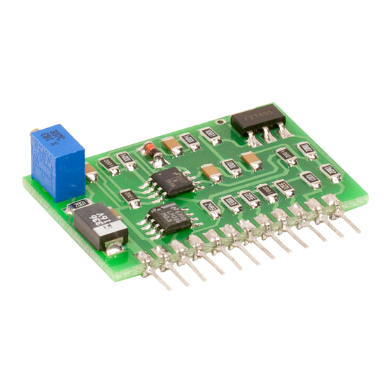
12-pin SIP connector which allows simple integration into a printed circuit design. The LD1100 can drive lasers up to 250 mA in a constant-power mode. It uses the internal monitor photodiode for a feedback signal into a proportional-integral feedback loop to stabilize the output power to within 0.01%. - Page 6 LD1100 Figure 2 LD1100 Pinouts Signal Description Circuit Power, 8 to 12VDC, 250mA, NOTE: Internally tied to Laser Diode Anode, the laser anode must be isolated from the power supply COM. Circuit ground Internal 2.5 V reference Photodiode Anode Laser Diode Anode [internally tied to +V (pin 1)] Laser Diode Cathode When tied to common puts a 100 k...
-
Page 7: Chapter 4 Setup
The LD1100 has a pin-programmable feedback gain to accommodate a wide range of laser monitor photodiode currents. It is important that this gain be matched to the specific laser so that the LD1100 operates properly. Please refer to Figure 1 for identifying LD1100 features. For a detailed description of the feedback circuit as well as instructions on fully optimizing the gain, refer to Appendix. - Page 8 LD1100 Max I (mA) 100 k 33 k 10 k 3.3 k 1 k 0.010 0.035 0.085 0.110 0.260 0.285 0.335 0.360 0.767 0.792 0.843 0.868 1.017 1.042 1.093 1.118 2.510 2.535 2.585 2.610 2.760 2.785 2.835 2.860 3.267 3.292 3.343...
-
Page 9: Dc Power Supply Connection
DC supplies. The LD1100 can also be operated off a battery. The usable lifetime of the battery will be limited to the laser operating current and the battery capacity. -
Page 10: Four Pin Laser Diodes
4.3.1 or 4.3.2. 4.4. Accessories Thorlabs offers evaluation boards as well as pre-assembled kits for the LD1100 to make set up and testing even easier. Please refer to Chapter 7 for setup and operation of the EB1100, EK1101, EK1102. Page 9... -
Page 11: Chapter 5 Operation
5.2. ON / OFF Control The LD1100 has an external ON / OFF control (J1, pin 3) which allows the laser output to be set to a reduced level. This function is activated by pulling this pin to 0V using either a mechanical switch or a transistor (open-drain FET or open- collector bipolar). -
Page 12: Chapter 6 Feedback Circuit Operation
LD1100 Chapter 6 Feedback Circuit Operation The LD1100 uses a proportional-integral type (PI) feedback circuit to maintain an extremely stable laser output. The laser power is stabilized by varying the laser drive current in response to the monitor photodiode feedback to maintain a constant output power. - Page 13 32 possible resistor combinations. Note that with all five resistors open, the LD1100 still has a 249 K resistor (R6) in the feedback loop. This was set so that the feedback loop will safely saturate before the laser is overdriven for most lasers (assuming the output control is turned down before powering up).
-
Page 14: Eb1100 Evaluation Board, Ek1101 & Ek1102 Evaluation Kits
Chapter 7 EB1100 Evaluation Board, EK1101 & EK1102 Evaluation Kits Thorlabs offers two options to make setup and operation of the LD1100 Laser Driver easier. The EB1100 is an evaluation printed circuit board that the user can install the LD1100 onto and connect to the laser and power supply using components supplied by the user. -
Page 15: Dc Power Supply Connections
(12 turns counter clockwise). EB1100 Users: the ON / OFF position on the EB1100 can be used with a single pole, single throw switch. Power to the LD1100 is provided when pin 1 of this connector is jumpered to pin 2. -
Page 16: Ek1101: Laser Anode - Photodiode Cathode Common
LD_C WARNING The LD1100 places the laser anode and cathode at a voltage above gorund. The laser mount should be electrically isolated form the power supply used to operate the EB1100. For best results use a floating power supply that has outputs isolated from the AC ground to run the EB1100 and connect the laser mout to a suitable earth ground to improve ESD protection. -
Page 17: Ek1101 And Ek1102 Operation
Where provided, use the actual performance data supplied with the diode. This is usually found on the outside of the diode wrapper or provided on a separate data sheet. If in doubt, please call a Thorlabs engineer and we will be happy to assist you. -
Page 18: Monitoring The Laser Operating Current
Check that the power supply voltage is between 8 and 12 V. If using a battery, replace with a new battery. Check that the power switch is ON. If you still experience problems, please call Thorlabs and an engineer will be happy to assist you. Page 17... -
Page 19: Chapter 8 Troubleshooting
Chapter 8: Troubleshooting Chapter 8 Troubleshooting Once it is set up, the LD1100 should be easy to operate and provide many hours of use. In case you experience any problems, we‟ve included a few checks to help in troubleshooting the problem. If you have any questions, please call the factory and a Thorlabs engineer will be happy to assist you. -
Page 20: Chapter 9 Specifications
LD1100 Chapter 9 Specifications Performance Specifications Operating Mode Constant-Power (Photodiode Feedback) 0 – 250 mA Output Current Output Control 12-Turn Potentiometer (On-Board) Output Stability <0.01% Output Noise 0.1 µA (RMS) Feedback Gain On-Board, Pin-Programmable, Also Externally Configurable 5 µA – 5 mA... - Page 21 LD1100 Chapter 9: Specifications Figure 6 LD1100 Pinouts Signal Description Circuit Power, 8 to 12VDC, 250mA, NOTE: Internally tied to Laser Diode Anode, the laser anode must be isolated from the power supply COM. Circuit ground Internal 2.5 V reference...
-
Page 22: Chapter 10 Regulatory
10.1. Waste Treatment is Your Own Responsibility If you do not return an “end of life” unit to Thorlabs, you must hand it to a company specialized in waste recovery. Do not dispose of the unit in a litter bin or at a public waste disposal site. -
Page 23: Chapter 11 Thorlabs Worldwide Contacts
Chapter Thorlabs Worldwide Contacts For technical support or sales inquiries, please visit us at www.thorlabs.com/contact for our most up-to-date contact information. USA, Canada, and South America UK and Ireland Thorlabs, Inc. Thorlabs Ltd. sales@thorlabs.com sales.uk@thorlabs.com techsupport@thorlabs.com techsupport.uk@thorlabs.com Europe Scandinavia Thorlabs GmbH Thorlabs Sweden AB europe@thorlabs.com... - Page 24 www.thorlabs.com...
Need help?
Do you have a question about the LD1100 and is the answer not in the manual?
Questions and answers