Table of Contents
Advertisement
Advertisement
Table of Contents

Related Manuals for THORLABS LCC25


Summary of Contents for THORLABS LCC25
- Page 1 LCC25 Liquid Crystal Controller Operating Manual...
-
Page 2: Table Of Contents
Part 3. Setup and Operation ................ 7 AC Line Voltage ......................7 Powering ON the LCC25 ....................7 Setting the Voltage and Modulation Frequency .............. 7 Setting the Output ......................8 Internal Modulation Frequency ..................8 ... - Page 3 A 2 kHz Square Wave Output with 150 Hz Modulation ........ 6 Figure 3: Front Display ....................6 Figure 4: LCC25 Front Panel ..................11 Figure 5: LCC25 Rear Panel Features ................. 11 Figure 6: LCC25 Mechanical Drawing ............... 13 18828-D02 Rev F, Sept 23, 2011 Page 3 www.thorlabs.com...
-
Page 4: Part 1. Important Safety Notice
Liquid Crystal Controller Part 1. Important Safety Notice Do Not Open Housing! The LCC25 has no user-serviceable parts. Service should only be performed by trained service personnel. All statements regarding safety of operation and technical data in this instruction manual will only apply when the unit is operated correctly. -
Page 5: Part 2. Product Overview
USB interface, controls the retardance of the LC device. The LCC25 produces a 2 kHz AC square wave with an amplitude that is adjustable from 0 to 25 V The unit features two selectable set points, Voltage 1 and Voltage 2. -
Page 6: Figure 2: A 2 Khz Square Wave Output With 150 Hz Modulation
Liquid Crystal Controller Figure 2: A 2 kHz Square Wave Output with 150 Hz Modulation The LCC25 will automatically detect and correct any DC offset in real time to within ±10 mV. This feature increases the life of the liquid crystal device. -
Page 7: Part 3. Setup And Operation
AC Line Voltage The LCC25 is designed to operate at 100 to 240 VAC operation. There is no line switch adjustment to be made. However it may be necessary to replace an open fuse. To do this you must perform the following procedure on page 14, Fuse Replacement. -
Page 8: Setting The Output
0.5 to 500 Hz, and any duty cycle, but must be 0 and 5 Volts to trigger the flip. The output from the LCC25 will be modulated based on the input frequency with Voltage 1 being the high and Voltage 2 being the low. -
Page 9: Computer Controlled Operation
Liquid Crystal Controller Computer Controlled Operation The LCC25 may also be controlled by a command line language through the USB port. This is offered to enable operation through a terminal interface or for those who may want to write their own program to control the unit. The command language is described below. - Page 10 Set voltage. Locks out use of buttons Locks out buttons on from panel. Command Query Returns a list of these commands *) All commands and queries are in lower case letters. 18828-D02 Rev F, Sept 23, 2011 Page 10 www.thorlabs.com...
-
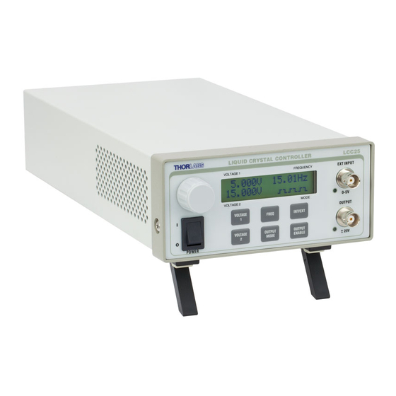
Page 11: Lcc25 Controls And Features
Rotary Knob LCD Display External Input BNC Main Power Switch Function Keys Output BNC Figure 4: LCC25 Front Panel AC Input Connector-IEC and Fuse Drawer Figure 5: LCC25 Rear Panel Features 18828-D02 Rev F, Sept 23, 2011 Page 11 www.thorlabs.com... -
Page 12: Part 4. Lcc25 Specifications
Liquid Crystal Controller Part 4. LCC25 Specifications Specification Description Max Ratings Max Output Current 15 mA Max External Input Voltage 5 VDC Fuse Rating 500 mA, 5 x 20 mm SLO-BLO *See replacement spec. page 14 Operating Temperature Range 10 to 40 °C... -
Page 13: Mechanical Drawing
Liquid Crystal Controller 4.1. Mechanical Drawing 12.160" (308.88mm) 11.425" (290.2mm) 2.586" 3.066" (65.69mm) (77.88mm) 5.758" (146.26mm) Figure 6: LCC25 Mechanical Drawing 18828-D02 Rev F, Sept 23, 2011 Page 13 www.thorlabs.com... -
Page 14: Part 5. Maintenance
The enclosure may be cleaned by wiping with a soft damp cloth. There are no serviceable parts in the LCC25 and no reason to open the unit. If you suspect a problem with your LCC25 please call Thorlabs and technical support will be happy to assist you. -
Page 15: Troubleshooting
Thorlabs technical support for assistance. Note: The LCC25 circuitry has been designed to monitor and correct the DC offset in real time. This will increase the life of the Liquid Crystals. For any unforeseen reason DC offset is detected above the ±10 mV limit enabling the DC OFFSET ERROR to appear. -
Page 16: Part 6. Warranty Information
Lasers and Imaging Systems Thorlabs offers a one year warranty on all lasers and imaging systems, with the exceptions of laser diodes. Some products are warranted for the number of hours specified in the operating manual of each laser. -
Page 17: Part 7. Declaration Of Conformity
Liquid Crystal Controller Part 7. Declaration of Conformity 18828-D02 Rev F, Sept 23, 2011 Page 17 www.thorlabs.com... -
Page 18: Part 8. Regulatory
Waste Treatment is Your Own Responsibility If you do not return an “end of life” unit to Thorlabs, you must hand it to a company specialized in waste recovery. Do not dispose of the unit in a litter bin or at a public waste disposal site. -
Page 19: Part 9. Thorlabs Worldwide Contacts
Liquid Crystal Controller Part 9. Thorlabs Worldwide Contacts USA, Canada, and South America Thorlabs, Inc. 56 Sparta Avenue Newton, NJ 07860 Tel: 973-579-7227 Fax: 973-300-3600 www.thorlabs.com www.thorlabs.us (West Coast) Email: sales@thorlabs.com Support: techsupport@thorlabs.com Europe UK and Ireland Thorlabs GmbH Thorlabs Ltd. - Page 20 www.thorlabs.com...
Need help?
Do you have a question about the LCC25 and is the answer not in the manual?
Questions and answers