THORLABS Blueline Series Operation Manual
Laser diode controller
Hide thumbs
Also See for Blueline Series:
- Operation manual (119 pages) ,
- Operating manual (80 pages) ,
- Operation manual (87 pages)
Table of Contents
Advertisement
Quick Links
Advertisement
Table of Contents

Related Manuals for THORLABS Blueline Series


Summary of Contents for THORLABS Blueline Series
- Page 1 Operation Manual Thorlabs Blueline™ Series Laser Diode Controller LDC2xx 2006...
- Page 2 Version: 1.11 Date: 20.06.2006 © Copyright 2006, Thorlabs GmbH, Germany...
-
Page 3: Table Of Contents
Contents page General Information 1.1 At a Glance 1.2 Safety 1.3 Ordering codes and accessories Getting Started 2.1 Unpacking 2.2 Preparation 2.3 Operating elements 2.3.1 Operating elements on front panel 2.3.2 Operating elements on rear panel 2.4 First operation Operating the LDC2xx 3.1 Connecting components 3.1.1 9-pole SUB-D output jack... - Page 4 Individual data LDC202B 6.3.5 Individual data LDC205B 6.3.6 Individual data LDC210B 6.3.7 Individual data LDC220 6.4 Thorlabs “End of Life” policy (WEEE) 6.4.1 Waste treatment on your own responsibility 6.4.2 Ecological background 6.5 List of acronyms 6.6 List of figures...
- Page 5 Therefore, please let us know about possible criticism or ideas. We and our international partners are looking forward to hearing from you. Thorlabs GmbH This part of the instruction manual contains all the specific information on how to operate a current module LDC2 xx.
-
Page 7: General Information
1.1 At a Glance The laser diode controllers of the series LDC200 by are extremely Thorlabs GmbH precise controllers for laser diodes and LEDs. If a temperature controller by Thorlabs is used additionally the injection current or the optical output power and the GmbH temperature of the connected laser diode can be controlled simultaneously. - Page 8 With free air circulation a safe operation of the unit is guaranteed up to 40 °C ambient temperature. Attention Do not obstruct the air-ventilation slots in the housing! If a laser diode head and the corresponding cable (CAB 400) by Thorlabs GmbH used, damages caused by wrong connections are impossible. LDC2xx / page 2...
-
Page 9: Safety
Laser and photodiodes must only be connected with duly shielded connection cables. Only with written consent from Thorlabs GmbH may changes to single components be carried out or components not supplied by Thorlabs GmbH be used. This precision device is only dispatchable if duly packed into the complete original packaging including the plastic form parts. - Page 10 1.2 Safety Attention Laser modules can deliver up to several 100mW of (maybe) invisible laser radiation! When operated incorrectly, this can cause severe damage to your eyes and health! Be sure to pay strict attention to the safety recommendations of the appropriate laser safety class! This laser safety class is marked on your external laser source used.
-
Page 11: Ordering Codes And Accessories
1.3 Ordering codes and accessories Ordering codes and accessories Ordering-code Short description Laser diode controller, current range 0 ... 20 mA / 6 V LDC200V Laser diode controller, current range 0 ... 100 mA / 2.5 V LDC201U Ultra Low Noise Laser diode controller, current range 0 ... -
Page 12: Getting Started
2.1 Unpacking 2 Getting Started 2.1 Unpacking Inspect the shipping container for damage. If the shipping container seems to be dam aged, keep it until you have inspected the contents and you have inspected the LDC2xx mechanically and electrically. Verify that you have received the following items: 1. -
Page 13: Operating Elements
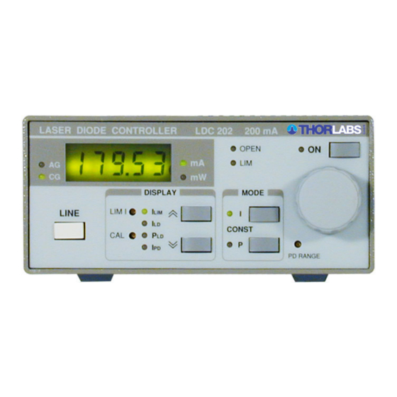
2.3 Operating elements 2.3 Operating elements 2.3.1 Operating elements on front panel L1 L2 L4 L5 L6 L7 L12 L13 L14 L15 L16 L17 L18 L19 L20 L21 L22 L23 L24 Figure 1 Display- and operating elements at the front panel LED "AG"... -
Page 14: Operating Elements On Rear Panel
2.3 Operating elements 2.3.2 Operating elements on rear panel Figure 2 Operating elements on the rear panel Modulation input/ analog control input "MOD IN", -10V … +10 V Analogue control output "CTL OUT", 0 … ±10V Connector for chassis ground Connector "LD OUT"... -
Page 15: First Operation
2.4 First operation 2.4 First operation Turn the unit on by means of the line switch (L11). Via the connector jack of the chassis ground (R 4) the external optical build-up can be connected to ground potential, if required. The ground pi n of the laser diode is internally connected to chassis ground. -
Page 16: Operating The Ldc2Xx
3.1.1 9-pole SUB-D output jack The laser diode controller LDC2xx by can (according to the version) Thorlabs GmbH drive all laser diodes up to a maximum current rate of 2 A. If laser mounts by are used just connect the input "LD DRIVER" of Thorlabs GmbH the laser mount to the output jack "LD OUTPUT"... -
Page 17: Interlock And Control Led For Laser On
3.1 Connecting components 5-4-3-2-1 9-8-7-6 Figure 3 Pin assignment of the "LD OUTPUT"jack (female) pin connection open circuit monitoring, status display: interlock and status LASER ON/OFF digital ground for pin 1 laser diode: laser diode cathode (at AG) laser diode anode (at CG) laser diode ground photodiode: photodiode cathode... -
Page 18: Connecting The Laser Diode And Photodiode
3.1 Connecting components Pin 1 and pin 5 must be connected externa lly by a wire (total resistance <430 Ω). When opening this connection, the LDC2xx swit ches automatically into LASER OFF mode. A LED can be connected in parallel to a resistor of <470 Ω between pin 1 and pin 5. This LED lights up when the laser current is switched on (LASER ON). - Page 19 3.1 Connecting components The laser diode is always sourced with re spect to ground. Compared to a floating driver stage, this operation mode has the advantages of higher security for the laser diode and better stability of the laser current. If the photodiode shall be operat ed with bias voltage a battery can be connected in series to the photodiode.
-
Page 20: Analog Control Output For The Laser Current
3.1 Connecting components 3.1.4 Analog control output for the laser current At the output "CTL OUT" (R2) a volt age proportional to the laser current "I " is available. E.g. a recorder, an oscilloscope or an A/D converter card can be connected directly to the output. -
Page 21: Setting The Current Limit "Ilim
3.2 Setting the current limit "ILIM" Setting the current limit "I " Before operating a laser diode always set the lim it for the injection current to protect the laser diode against destruction by operating errors. Switch on the unit with the button "LINE" (L11). If the unit had already been switched on before switch off the laser current with the key "ON"... - Page 22 3.3 Selecting the laser diode polarity Switch off the LDC2xx. Select the desired polarity with the switch "LD POL" (R6). For laser diodes with a built-in monitor diode the common pin of laser diode and photodiode is the ground pin. The selected polarity of the output is indicated with the LED "AG"...
-
Page 23: Constant Current Mode (Const I)
3.4 Constant current mode (CONST I) Constant current mode (CONST I) Switch on the LDC2xx. Select a suitable current limit "I " (refer to chapter 3.2). Select the appropriate laser polarity (refer to chapter 3.3). Connect the laser diode (refer to chapter 3.1.3). Select the display "I "... -
Page 24: Constant Power Mode (Const P)
3.5 Constant power mode (CONST P) If the connection to the laser diode is in terrupted during operat ion the laser diode current is switched off autom atically. LED "ON" (L8) ex tinguishes, LED "OPEN" (L6) lights up and a short beep is heard as warning signal. If the output is switched on wh ile the interlock is closed and there is no laser diode connected at first the LED "ON"... - Page 25 3.5 Constant power mode (CONST P) By pressing "ON" (L9) switch off the laser current. Select constant power (CONST P) with "P" (L22). Set the adjust knob (L10) completely to the left. Switch on the output by pressi ng "ON" (L9). The LED "ON" (L8) lights up, the output is activated and the current slowly increas es (about 1 s) to the value set with the knob (L10).
-
Page 26: Changing The "Ipd" Setting Range
3.5 Constant power mode (CONST P) After pressing "ON" (L9) the LED "OPEN " (L6) extinguishes and the laser diode current output can be switched on again by pressing "ON" (L9). The laser current can be modulated via t he connector "MOD IN" (R3) (refer to chapter 3.7). -
Page 27: Calibrating The Optical Power Display
3.6 Calibrating the optical power display Calibrating the optical power display Additional to the photodiode current "I " also the optical power of the laser diode can be displayed. The actual optical power is shown only after calibration of the power display. -
Page 28: Over-Temperature-Protection Of The Ldc2Xx
3.8 Over-temperature-protection of the LDC2xx Connect the modulation source to the ja ck "MOD IN" (R1). Avoid ground loops when connecting the function generator. The laser diode current "I " can be supervised at the anal og output "CTL OUT" (R2) (refer to chapter 3.1.4). -
Page 29: Remote Control
3.8 Over-temperature-protection of the LDC2xx 4 Remote control The units of the LDC200 series do not provide any standard computer interface. By using the analog inputs and outputs however simple semi-automatic systems may be build up. The following control or read back functions are possible: Interlock If a relay contact or an open collector transisto r is inserted in the interlock line (refer to chapter 3.1.2), the output can be switched off automatically at any time. -
Page 30: Maintenance And Repair
The LDC2xx does not contain any modules that can be repaired by users. If a malfunction occurs send the unit to for repair. Thorlabs GmbH To guarantee the specifications given in chapter 6.3 over a long period it is recommended to have the unit calibrated by every two years. -
Page 31: Line Voltage Setting
5.2 Line voltage setting Line voltage setting The laser diode controller LDC200 operates at fixed line voltages of 90 V … 115 V, 104 V … 132 V or 207 V … 264 V. The Line voltage setting can be changed only by qualified service personnel. Disconnect Power. -
Page 32: Replacing The Mains Fuse
5.3 Replacing the mains fuse Replacing the mains fuse If the mains fuse has opened due to line distor tions, incorrect line voltage or other causes, it can be easily replaced from the rear without opening the unit. Attention To avoid risk of fire only the appropriate fuse for the corresponding line voltage must be used. -
Page 33: Internal Fuse Replacement
5.4 Internal Fuse Replacement 5.4 Internal Fuse Replacement Internal fuses must be changed only by qualified service personnel. Open the unit like described in section 5.2. Depending on the type of LDC2xx(B), you will find adhesive labels on the transformer depicting type and location of the internal fuses. -
Page 34: Troubleshooting
5.5 Troubleshooting 5.5 Troubleshooting In case that your LDC200 system show s malfunction please check the following items: Module does not work at all (no display on the mainframe): Mainframe LDC200 connected properly to the mains? Connect the LDC200 to the power line paying attention to the right voltage setting of your mainframe. - Page 35 If you don’t find the error source by means of the trouble shooting list please first contact the before sending the Thorlabs GmbH-Hotline ( europe@thorlabs.com) LDC200 for checkup and repair to - Germany. Thorlabs GmbH (refer to section 6.7, “Addresses ” on page 43)
-
Page 36: Appendix
6.1 Warranty 6 Appendix 6.1 Warranty warrants material and production of the LDC2xx for a period of 24 Thorlabs GmbH months starting with the date of shipment. During this warranty period Thorlabs will see to defaults by repair or by exchange if these are entitled to warranty. -
Page 37: Certifications And Compliances
6.2 Certifications and compliances 6.2 Certifications and compliances Certifications and compliances Category Standards or description EC Declaration Meets intent of Directive 89/336/EEC for Electromagnetic Compatibility. of Conformity - Compliance was demonstrated to the following specifications as listed in the Official Journal of the European Communities: EN 61326 EMC requirements for Class A electrical equipment for measurement, control and laboratory use,... - Page 38 6.2 Certifications and compliances Certifications and compliances Category Standards or description EC Declaration Compliance was demonstrated to the following specification as listed in the of Conformity - Official Journal of the European Communities: Low Voltage Low Voltage Directive 73/23/EEC, amended by 93/68/EEC EN 61010-1/A2:1995 Safety requirements for electrical equipment for measurement control...
-
Page 39: Technical Data
6.3 Technical data 6.3 Technical data 6.3.1 Common Data (All technical data are valid at 23 ± 5°C and 45 ±15% humidity) Connectors: Laser diode, photodiode, LD ON signal, Interlock (0 … 5 V) LD OUTPUT 9-pin D-Sub-jack Modulation input (-10 V … +10 V) MOD IN Control output (0 …... -
Page 40: Individual Data Ldc200V
6.3 Technical data 6.3.2 Individual data LDC200V Constant current mode: Control range (continuously variable) 0 ... ± 20 mA Setting / Measurement Resolution 1 µA Accuracy ± 20 µA Compliance voltage > 6 V Noise without ripple (10 Hz ... 10 MHz), typ. <<... -
Page 41: Individual Data Ldc201U
6.3 Technical data 6.3.3 Individual data LDC201U Constant current mode: Control range (continuously variable) 0 ... ± 100 mA Setting / measurement resolution 10 µA Accuracy ± 50 µA Compliance voltage > 2.5 V Noise without ripple (10 Hz ... 10 MHz), typ. <... -
Page 42: Individual Data Ldc202B
6.3 Technical data 6.3.4 Individual data LDC202B Constant current mode: Control range (continuously variable) 0 ... ± 200 mA Setting / measurement resolution 10 µA Accuracy ± 0.1 mA Compliance voltage > 10 V Noise without ripple (10 Hz ... 10 MHz), typ. <... -
Page 43: Individual Data Ldc205B
6.3 Technical data 6.3.5 Individual data LDC205B Constant current mode: Control range (continuously variable) 0 ... ± 500 mA Setting / measurement resolution 0.1 mA Accuracy ± 0.1 mA Compliance voltage > 10 V Noise without ripple (10 Hz ... 10 MHz), typ. <... -
Page 44: Individual Data Ldc210B
6.3 Technical data 6.3.6 Individual data LDC210B Constant current mode: Control range (continuously variable) 0 ... ± 1 A Setting / measurement resolution 0.1 mA Accuracy ± 1 mA Compliance voltage > 10 V Noise without ripple (10 Hz ... 10 MHz), typ. <... -
Page 45: Individual Data Ldc220
6.3 Technical data 6.3.7 Individual data LDC220 Constant current mode: Control range (continuously variable) 0 ... ± 2 A Setting / measurement Resolution 0.1 mA Accuracy ± 2 mA Compliance voltage > 4 V Noise without ripple (10 Hz ... 10 MHz) <... -
Page 46: Thorlabs "End Of Life" Policy (Weee)
(PCB’s, housings etc.). • If you wish to return a Thorlabs unit for wa ste recovery, please contact Thorlabs or your nearest dealer for further information. 6.4.1 Waste treatment on your own responsibility If you do not return an “end of life”... -
Page 47: Ecological Background
6.4 Thorlabs “End of Life” policy (WEEE) 6.4.2 Ecological background It is well known that WEEE pollutes the environment by releasing toxic products during decomposition. The aim of the Eu ropean RoHS directive is to reduce the content of toxic substances in electronic products in the future. -
Page 48: List Of Acronyms
6.5 List of acronyms 6.5 List of acronyms The following acronyms are used in this manual: Alternating Current Anode Ground Constant Current mode Cathode Ground Constant Power mode Direct Current Laser Diode Laser Diode Controller Light Emitting Diode Over TemPerature Photo Diode Thermo Electric Cooler (Peltier Element) VCSEL... -
Page 49: Addresses
6.7 Addresses 6.7 Addresses Our Company is represented by several di stributors and sales offices throughout the world. Europe Thorlabs GmbH Gauss-Strasse 11 D-85757 Karlsfeld Germany Sales and Support Phone: +49 (0) 81 31 / 5956-0 Fax: +49 (0) 81 31 / 5956-99 Email: europe@thorlabs.com... - Page 50 6.7 Addresses Japan Thorlabs, Inc. 3-6-3, Kitamachi, Nerima-ku, Tokyo 179-0081 Japan Sales and Support Phone: +81-3-6915-7701 Fax: +81-3-6915-7716 Email: sales@thorlabs.jp Web: www.thorlabs.co.jp Please call our hotlines, send an Email to ask fo r your nearest distributor or just visit our homepage http://www.thorlabs.com...
- Page 51 6.7 Addresses laserdiode ........12 ld output ........... 11 A/D ...........23 letterplate ........... 8 accessories.........5 limit (current)........7 acronyms ..........42 line voltage........25 addresses .........43 mains voltage....... 8, 25 calibration .........21 modulation ........21 cc............17 certifications........31 cleaning ..........24 operating elements ......7 compliances........31 connector..........10 packing list .........
Need help?
Do you have a question about the Blueline Series and is the answer not in the manual?
Questions and answers