Table of Contents
Advertisement
Quick Links
Advertisement
Table of Contents

Subscribe to Our Youtube Channel
Related Manuals for THORLABS LCC2415-VIS


Summary of Contents for THORLABS LCC2415-VIS
- Page 1 LCC2415-VIS Liquid Crystal Retarder with Integrated Controller User Guide...
-
Page 2: Table Of Contents
Liquid Crystal Retarder with Integrated Controller Table of Contents Warning Symbol Definitions ........3 Safety ................4 Product Overview ............5 Getting Started ............7 4.1 Parts List .............. 7 4.2 Physical Description .......... 7 4.3 ... - Page 3 Appendix ..............32 7.1 Specifications ............ 32 7.2 Mechanical Drawing .......... 33 Certifications and Compliances ......34 Regulatory ..............35 9.1 Waste Treatment is Your Own Responsibility .. 35 9.2 Ecological Background ........... 35 Thorlabs Worldwide Contacts ........ 36 Page 2...
-
Page 4: Warning Symbol Definitions
Liquid Crystal Retarder with Integrated Controller Warning Symbol Definitions Below is a list of warning symbols you may encounter in this manual or on your device. Symbol Description Direct Current Alternating Current Both Direct and Alternating Current Earth Ground Terminal Protective Conductor Terminal Frame or Chassis Terminal Equipotentiality... -
Page 5: Safety
LCC2415-VIS Chapter 2: Safety Safety DO NOT OPEN HOUSING The retarder has no user-serviceable parts. Service should only be performed by trained service personnel. All statements regarding safety of operation and technical data in this instruction manual will only apply when the unit is operated correctly. -
Page 6: Product Overview
Liquid Crystal Retarder with Integrated Controller Product Overview Thorlabs’ Multi-Wave Liquid Crystal Variable Retarders (LCVR) with integrated controller use a nematic liquid crystal cell to function as a wide range variable wave plate. They consist of a Liquid Crystal (LC) cell, a compensating fixed wave plate, and a built-in controller. - Page 7 Figure 3.2: Voltage-Retardance Curve of a Multi-Wave Liquid Crystal Variable Retarder The built-in controller of the liquid crystal retarder communicates with a PC via either USB or Bluetooth, and can be operated by Thorlabs’ software GUI and/or controlled by external input trigger signal. Page 6...
-
Page 8: Getting Started
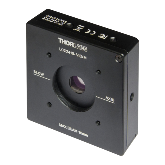
Liquid Crystal Retarder with Integrated Controller Getting Started Parts List The package contains the following items: 1 LCC2415 Multi-Wave Liquid Crystal Variable Retarder 1 USB Cable 1 Operation Manual 1 CD Containing the Software Physical Description Fig 4.1 shows the physical package of the LCC2415 Liquid Crystal Variable Retarder. -
Page 9: Connection Overview
LCC2415-VIS Chapter 4: Getting Started Connection Overview There are two electrical ports on the liquid crystal retarder: a mini USB port and an SMC port for external triggers. The USB port provides power to the unit and can be used to communicate with a PC for retarder control. -
Page 10: Mounting And Alignment
There is one 8-32 (M4) mounting hole on each of the unengraved side panels of the LCC2415. Utilizing Thorlabs’ standard half-inch posts and post holders, users can use them to mount the unit to a breadboard or optical table with the slow axis in the vertical or horizontal direction, as shown in Figure 4.4. -
Page 11: Software Installation
LCC2415-VIS Chapter 4: Getting Started using an externally SM1-threaded lens tube coupler (Item # SM1T2), it can be connected to a CRM1P rotation stage, giving users the ability to rotate and fine tune the slow axis direction of the retarder. The slow axis is marked on both side of the enclosure. -
Page 12: Gui Operation
Liquid Crystal Retarder with Integrated Controller GUI Operation Establishing a Connection Set up the devices following either method in Chapter 4.4. Make sure the Power Indicator LED is on. If you are operating the unit using Bluetooth, make sure your PC has an enabled Bluetooth module. Double-click the shortcut on the desktop to launch the software GUI, and click the connect button on the main window. - Page 13 LCC2415-VIS Chapter 5: GUI Operation A port selection window will appear. The software will list all available devices (e.g., COM1, COM2, and so on). If the device is connected to a PC via USB (with no Bluetooth module), only the USB devices will be listed. If the unit is powered by a mobile phone charger and connected to the PC via Bluetooth, only the Bluetooth devices will be listed.
-
Page 14: Software Gui
Liquid Crystal Retarder with Integrated Controller Software GUI Figure 5.3 shows the main window of the software GUI. It consists of the following elements: The toolbar; The main operation area, where users can toggle between different control and operation modes, and set the operating wavelength and retardance values;... -
Page 15: Toolbar
LCC2415-VIS Chapter 5: GUI Operation Toolbar There are a few buttons on the toolbar, the function of which is described below: Connect/Disconnect: Connect or disconnect the LCC2415 from the Save: Save all current settings in XML format. Load: Load saved settings. -
Page 16: Retardance Mode
Liquid Crystal Retarder with Integrated Controller 5.4.1 Retardance Mode In this mode, users can input the desired retardance value directly into the UI. As mentioned in Chapter 1, each unit is calibrated before shipment for retardance-voltage response from 400 nm to 700 nm, and the calibration data is saved in the unit. -
Page 17: Voltage Mode
LCC2415-VIS Chapter 5: GUI Operation 5.4.2 Voltage Mode In this mode, the software allows direct entry of the voltage applied to the liquid crystal cell. There is no need in this mode to set the working wavelength (which acts as a calibration factor in Retardance Mode), so the working wavelength slider is removed. - Page 18 Liquid Crystal Retarder with Integrated Controller Figure 5.7: Inserting a Step To change the retardance/voltage value and the interval of a certain step, simply click the value and type in in the desired number. Figure 5.8: Changing a Step Value Users can also insert a sequence by right-clicking on the sequence table and choosing “Insert Sequence.”...
- Page 19 LCC2415-VIS Chapter 5: GUI Operation Fig 5.9: Inserting a Sequence Defined by Start, End, and Step Size To start a sequence, type in how many cycles the sequence needs to be played and click the play buttom below the sequence table.
- Page 20 Liquid Crystal Retarder with Integrated Controller Figure 5.11: Click Stop Buttom to stop a Sequence Users can also save the current sequence as a CSV format file and import sequences saved in CSV format. To do so, simply right-click the sequence table and choose “Export to csv”...
-
Page 21: Trigger Control Mode
LCC2415-VIS Chapter 5: GUI Operation Trigger Control Mode Click the Trigger button to enter Trigger Control Mode. In trigger mode, users may input a series of retardance/voltage settings and use an external TTL signal to move between steps in the series. -
Page 22: Command-Line Operation
Command-Line Operation Command-Line Interface Overview The LCC2415-VIS can be controlled by a command-line language through the USB port or Bluetooth. Users can either use a terminal emulator or write their own program to control the unit. The command language is described below. - Page 23 LCC2415-VIS Chapter 6: Command-Line Operation after a command is accepted by the controller, indicating it is ready to receive the next command. If the command is incorrect, the controller returns CMD_NOT_DEFINED; if the setting value is out of range, it returns CMD_ARG_RANGE_ERR; if the command is not operated in right condition, it returns CMD_Not_Set or CMD_Invalid.
-
Page 24: Command Summary
Liquid Crystal Retarder with Integrated Controller Command Summary The table below lists all the available commands for operation of the LCC2415. Command Syntax Description Returns the model number, *idn? or *IDN? Get ID hardware and firmware versions Get Specification Returns wavelength and retardance range Returns current communication Get Communication... -
Page 25: Description Of Commands
6.3.1 *idn? – Device Information Queries the device part number, hardware and firmware versions. Return: THORLABS LCC2415-VIS HWx.x FWx.x SNxxxxxxxx where HW is the hardware version; FW is the firmware version; and SN is the series number. 6.3.2 SP? – Device Wavelength and Retardance Range Queries the range of wavelength and retardance that the device supports. -
Page 26: Cf? - Device Communication Method
Liquid Crystal Retarder with Integrated Controller 6.3.3 CF? – Device Communication Method Queries device communication method. Return: CF=n where n is 1 or 2. CF=1, USB is being used for communication; CF=2, Bluetooth is being used for communication. 6.3.4 TP? – LC Retarder Temperature The TP? command queries the temperature of the LC retarder on the device. -
Page 27: Re=N; Re? - Retardance
LCC2415-VIS Chapter 6: Command-Line Operation 6.3.6 RE=n; RE? – Retardance The RE command can be used to set or query the retardance. 6.3.6.1 RE=n Sets the retardance. The value of n must be within REmin and REmax (defined in Section 6.3.2) and must be a multiple of 1 nm. -
Page 28: Om=N; Om? - Operation Mode
Liquid Crystal Retarder with Integrated Controller 6.3.8.1 CM=n Sets the control mode. The value of n can be one of the following: n=1: Manual n=2: Sequence (external trigger input) 6.3.8.2 Queries the current control mode. Return: CM=n where n is the current control mode (defined in Section 6.3.8.1). 6.3.9 OM=n;... - Page 29 LCC2415-VIS Chapter 6: Command-Line Operation 6.3.10.2 RSn? Queries the retardance of a particular sequence entry, where n is the sequence index. Return: RSn=n1 where n1 is the retardance for the requested sequence index. If the index of the sequence entry is out of the current list range, the controller returns CMD_ARG_RANGE_ERR.
-
Page 30: Ri=N1 N2 - Insert Into Sequence
Liquid Crystal Retarder with Integrated Controller 6.3.11 RI=n1 n2 – Insert into Sequence The RI command is used to insert sequence entries into the existing sequence list, where: n1 is the sequence index n2 is the set retardance The index to be inserted must be within the list that is already set up. That is, it cannot be used to specify an index which is out of the range of the current list, in contrast to the RS command. - Page 31 LCC2415-VIS Chapter 6: Command-Line Operation 6.3.14.2 VSn? Queries the voltage of a particular sequence entry, where n is the sequence index. Return: VSn=n1 where n1 is the voltage for the requested sequence index. If the index of the sequence entry is out of the current list range, the controller returns CMD_ARG_RANGE_ERR.
-
Page 32: Vi=N1 N2 - Insert Into Sequence
Liquid Crystal Retarder with Integrated Controller 6.3.15 VI=n1 n2 – Insert Into Sequence The VI command is used to insert sequence entries into the existing sequence list, where: n1 is the sequence index n2 is the set voltage The index to be inserted must be within the list that is already set up. That is, it cannot be used to specify an index which is out of the range of the current list, in contrast to the VS command. -
Page 33: Appendix
LCC2415-VIS Chapter 7: Appendix Appendix Specifications Specification Value Unit Liquid Crystal Material Nematic Liquid Crystal Retardance Range 0 - 4000 Retardance Resolution Retardance Accuracy ±1 Drive Voltage Range 0 - 10 Drive Voltage Resolution 0.001 Wavelength Range 400 - 700... -
Page 34: Mechanical Drawing
Liquid Crystal Retarder with Integrated Controller Mechanical Drawing 60.0 mm 8-32 (M4) Tapped Hole (2.36") 3.8 mm (0.15") Deep SMC Connector 30.0 mm for External Trigger (1.18") 30.0 mm 60.0 mm 4-40 Tapped Hole for (1.18") (2.36") 30 mm Cage Systems (4 Places, Both Sides) Internal SM1 (1.035"-40) Threads 8-32 (M4) Tapped Hole... -
Page 35: Certifications And Compliances
LCC2415-VIS Chapter 8: Certifications and Compliances Certifications and Compliances In accordance with European Council Directive 2004/108/EC, this product has been assessed against and found compliant with the following Applicable Standards: EN 55011: 2009+A1:2010 (Class B) EN 61326-1 : 2013 EN61000-3-2: 2006+A1:2009+A2:2009... -
Page 36: Regulatory
Thorlabs or your nearest dealer for further information. Waste Treatment is Your Own Responsibility If you do not return an “end of life” unit to Thorlabs, you must hand it to a company specialized in waste recovery. Do not dispose of the unit in a litter bin or at a public waste disposal site. -
Page 37: Thorlabs Worldwide Contacts
LCC2415-VIS Chapter 10: Thorlabs Worldwide Contacts Thorlabs Worldwide Contacts For technical support or sales inquiries, please visit us at www.thorlabs.com/contact for our most up-to-date contact information. USA, Canada, and South America UK and Ireland Thorlabs, Inc. Thorlabs Ltd. sales@thorlabs.com sales.uk@thorlabs.com techsupport@thorlabs.com... - Page 38 www.thorlabs.com...
Need help?
Do you have a question about the LCC2415-VIS and is the answer not in the manual?
Questions and answers