Advertisement
Quick Links
Advertisement

Related Manuals for THORLABS LDC2500B


Summary of Contents for THORLABS LDC2500B
- Page 1 LDC2500B Tapered Amplifier Controller User Guide...
-
Page 2: Table Of Contents
Chapter 2 Description ......................... 4 Chapter 3 Setup ........................... 5 3.1. Mounting the LD2500B ....................5 3.2. Mounting a Tapered Amplifier onto the LDC2500B ............ 5 3.3. Front Panel ........................5 Chapter 4 Operation ..........................7 4.1. Demo Software ......................7 4.2. -
Page 3: Chapter 1 Warning Symbol Definitions
Tapered Amplifier Controller Chapter 1: Warning Symbol Definitions Chapter 1 Warning Symbol Definitions Below is a list of warning symbols you may encounter in this manual or on your device. Symbol Description Direct Current Alternating Current Both Direct and Alternating Current Earth Ground Terminal Protective Conductor Terminal Frame or Chassis Terminal... -
Page 4: Chapter 2 Description
Interface, the LDC2500B hardware still has the priority. The control program will report the communication interface if data are being pulled out but have not been released by the LDC2500B. The two front panel buttons can be used to toggle the TECs and chip driving current as well as to turn the DC fan on and off. When both buttons are pressed at the same time, the DC fan will be toggled on and off. -
Page 5: Chapter 3 Setup
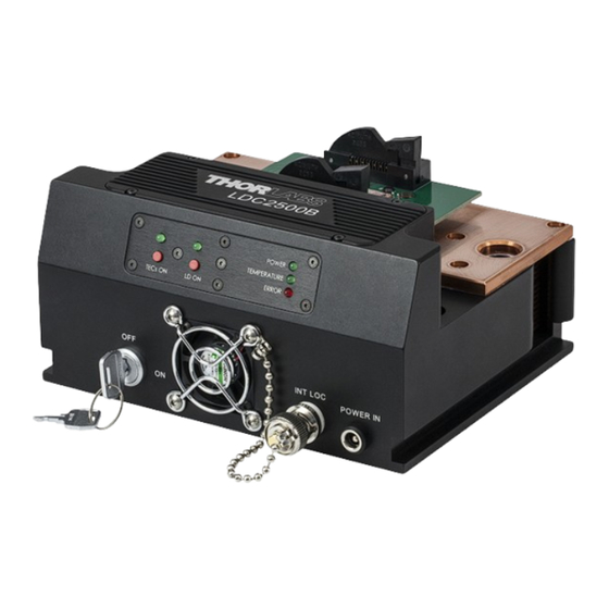
For the LDC2500B to be able to maintain stable chip and package temperatures, it is critical to make sure heat can be dissibated out of the uint. The LDC2500B cooling fan can be toggled on and off by pushing both front panel buttons in at the same time. - Page 6 INT LOC BNC: Jump Short to enable current output. An open connection will disable the current output. • One jump short BNC connector is connected as the factory default. Figure 2 Front Panel of the LDC2500B Rev C, August 26, 2013 Page 6...
-
Page 7: Chapter 4 Operation
“EXIT” GUI button, click the RUN arrow to restart the program. Note: Exiting the program will not change the settings on the LDC2500B status. 5. Set chip driving current limit (default driving current is 200 mA and default maximum current is 2500 mA). -
Page 8: Programming Guide
6 if necessary to achieve as table temperature readings as possible. 10. The LDC2500B can be used as a standalone driver. Front panel buttons, TECs ON and LD ON, can be used to toggle the TECs and LD ON/OFF. The software is only needed when parameters need to be modified. - Page 9 Example: after command 'e', output '0255' --> Tset(0) = 25.5° C. Read package temperature setting Tset(1) Example: after command 'f', output '0255' --> Tset(1) = 25.5° C. Read LDC2500B device serial number Example: after command 'n', output '0001' --> device serial number is 0001.
- Page 10 Example: 0 = 0%; 255 = 100%. System Error report. After command ‘C’, total of 3 characters will be shifted out of the LDC2500B User will need to convert the 3 characters to a 3 digit integer first. Example: “123”=123. And then convert the integer to one 8 bit binary format.
-
Page 11: Chapter 5 Specifications
Tapered Amplifier Controller Chapter 5: Specifications Chapter 5 Specifications LDC2500B Typical Drive Current 50 mA 2.5 A Compliance Voltage 2.5 V Current Stability ±2 mA Temperature Stability ±0.1 ° C TEC Current ±2.5 A Cooling Capacity* 10 W Power Consumption... -
Page 12: Chapter 6 Mechanical Drawing
Align Pin 1 of the Controller with Pin 1 of a 14-Pin Butterfly Amplifier. Only connect the jumper if the butterfly package has no integrated thermistor. Thorlabs’ Tapered Amplifiers have an integrated thermistor, so the default jumper setting is open. Please see Pin Diagram of Thorlabs' Tapered Amplifier below. -
Page 13: Appendix A: Pid Circuits
Tapered Amplifier Controller Chapter 7: Appendix A: PID Circuits Chapter 7 Appendix A: PID Circuits 7.1. PID Basics The PID circuit is often utilized as a control loop feedback controller and is very commonly used for many forms of servo circuits. The letters making up the acronym PID correspond to Proportional (P), Integral (I), and Derivative (D), which represents the three control settings of a PID circuit. -
Page 14: Pid Theory
Tapered Amplifier Controller Chapter 7: Appendix A: PID Circuits Please note that a PID circuit will not guarantee optimal control. Improper setting of the PID controls can cause the circuit to oscillate significantly and lead to instability in control. It is up to the user to properly adjust the PID gains to ensure proper performance. -
Page 15: Tuning
Tapered Amplifier Controller Chapter 7: Appendix A: PID Circuits Parameter Settling Steady-State Increased Rise Time Overshoot Time Error Stability Decrease Increase Small Change Decrease Degrade Decrease Decrease Increase Increase Degrade Significantly Improve Minor Decrease Minor Decrease Minor Decrease No Effect (for small K 7.3. -
Page 16: Chapter 8 Regulatory
Waste Treatment is Your Own Responsibility If you do not return an “end of life” unit to Thorlabs, you must hand it to a company specialized in waste recovery. Do not dispose of the unit in a litter bin or at a public waste disposal site. -
Page 17: Chapter 9 Thorlabs Worldwide Contacts
Chapter Thorlabs Worldwide Contacts For technical support or sales inquiries, please visit us at www.thorlabs.com/contact for our most up-to- date contact information. USA, Canada, and South America UK and Ireland Thorlabs, Inc. Thorlabs Ltd. sales@thorlabs.com sales.uk@thorlabs.com techsupport@thorlabs.com techsupport.uk@thorlabs.com Europe Scandinavia...
Need help?
Do you have a question about the LDC2500B and is the answer not in the manual?
Questions and answers