Table of Contents
Advertisement
Quick Links
User's Guide
ADI-2 Pro
FS R
Conversion done right
32 Bit / 768 kHz
Hi-Res Audio
SteadyClock
SyncCheck
FS
2 Channels Analog / Digital Converter
4 Channels Digital / Analog Converter
AES / ADAT / SPDIF Interface
32 Bit / 768 kHz Digital Audio
USB 2.0 Class Compliant
2 Extreme Power Headphone Outputs
Digital Signal Processing
Advanced Feature Set
Extended Remote Control
Advertisement
Table of Contents

Related Manuals for RME Audio ADI-2 Pro FS R


Summary of Contents for RME Audio ADI-2 Pro FS R
- Page 1 User’s Guide ADI-2 Pro FS R Conversion done right 32 Bit / 768 kHz Hi-Res Audio SteadyClock SyncCheck 2 Channels Analog / Digital Converter 4 Channels Digital / Analog Converter AES / ADAT / SPDIF Interface 32 Bit / 768 kHz Digital Audio USB 2.0 Class Compliant 2 Extreme Power Headphone Outputs Digital Signal Processing...
-
Page 2: Table Of Contents
General Introduction ............... 5 Package Contents ............. 5 System Requirements ..........5 Brief Description and Characteristics ..... 6 First Usage - Quick Start Connectors and Controls......... 7 Quick Start............... 8 Operation at the unit ..........8 Overview Menu Structure ........9 Playback .............. - Page 3 Warning Messages..........34 Modes 17.1 Auto ..............36 17.2 Preamp ..............37 17.3 AD/DA Converter ..........38 17.4 USB ..............39 17.5 Digital Through ............. 41 17.6 DAC..............42 Balanced Phones Mode .......... 43 DSD Operation 19.1 General ..............44 19.2 Direct DSD ............
- Page 4 Installation and Operation – iOS General ..............64 System Requirements ..........64 Setup................. 64 Supported Inputs and Outputs ......64 Technical Reference Technical Specifications 33.1 Analog Inputs ............66 33.2 Analog Outputs ............. 66 33.3 Digital Inputs ............67 33.4 Digital Outputs ............68 33.5 Digital ..............
-
Page 5: General
A DSD record and playback solution All there is left to say now is: Enjoy! 2. Package Contents ADI-2 Pro FS R Remote control with battery (MRC) Manual External switched power supply, lockable connector, DC 12 V 24 W ... -
Page 6: Brief Description And Characteristics
4. Brief Description and Characteristics The ADI-2 Pro is a 2-channel analog input to digital and 4-channel digital to analog output con- verter in a half-rack (9.5") enclosure of 1 U height. Latest 32 bit / 768 kHz converters offer up to 124 dBA signal to noise ratio. -
Page 7: First Usage - Quick Start
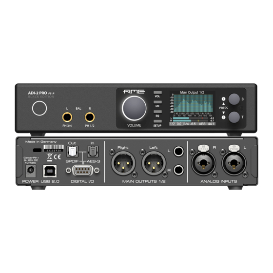
5. First Usage – Quick Start 5.1 Connectors and Controls The front of the ADI-2 Pro has 3 hi-precision rotary encoders with push function, 4 buttons, a standby power button, a high resolution IPS display, and two TRS headphone outputs. The output channels 1/2 and 3/4 feed two phones outputs via two independent Extreme Power driver circuits, optimized for both high and low impedance headphones. -
Page 8: Quick Start
5.2 Quick Start Connect the unit to the included power supply and push the Standby button to start. The ADI-2 Pro ships with Basic Mode Auto activated (SETUP – Options – Device Mode / DSD – Basic Mode). The input selection for SPDIF (coaxial or optical), and the source selection for Phones Out 3/4 are also set to Auto, the SRC is activated for the SPDIF input. -
Page 9: Overview Menu Structure
The unit has several informative screens on the top level. These are Global Level Meters, Ana- lyzer Input, Analyzer Output 1/2, Analyzer Output 3/4, State Overview and Dark Volume. Change between them by pushing encoder 1 or 2 whenever any of them is displayed. To quickly call them up simply press any of the 4 buttons several times. -
Page 10: Playback
5.5 Playback In the audio application being used, the ADI-2 Pro must be selected as output device. It can often be found in the Options, Preferences or Settings menus, as Playback Device, Audio De- vices, Audio etc. After selecting a device, audio data is sent to an analog or digital port, depend- ing on which has been selected as playback device. -
Page 11: Power Supply
6. Power Supply In order to make operating the ADI-2 Pro as flexible as possible, the unit has a universal DC input socket, accepting voltages from 9.5 Volts up to 15 Volts. An internal switching regulator of the latest technology with high efficiency (> 90%) prevents internal hum noise by operating above audible frequencies. -
Page 12: Features Explained
8. Features Explained 8.1 Extreme Power Headphone Outputs During the development of the ADI-2 Pro an extensive research on today’s headphone amp technology as well as headphones has been carried out. Many (many!) headphones later a max- imum output level of +22 dBu (10 Volt) was set as development goal, as it will drive even insen- sitive headphones sufficiently, while a maximum output current of around 260 mA per channel will result in lots of power for lower impedance phones (1.5 Watts @ 32 Ohm). -
Page 13: Dual Phones Outputs
8.2 Dual Phones Outputs Many features and design decisions on the ADI-2 Pro come from personal usage and experi- ence. For example when comparing headphones: it turns out to be very difficult when having just one headphone output. Changing the phones on the head is already a disrupting process which hinders easy comparison, but without proper level adjustment first, and the need to unplug one and to plug the other, comparisons are only possible for coarse differences. -
Page 14: Bass / Treble
This is one of the many major features that can’t be found on any similar device: a high-quality 5-band parametric EQ, usable at up to 768 kHz sample rate, easy to set up and adjust, with a graphical display showing the resulting curve, and multiple storage places including individual naming. -
Page 15: Src (Sample Rate Conversion)
Here is an example on how it works: the user’s typical lowest level listening volume is at -35 dB at the unit. This value is now set by the user as Low Vol Ref in the Loudness menu. Then Bass and Treble Gain can be set between 0 and +10 dB. -
Page 16: Dsp Limitations
Details on internal settings The Crossfeed effect is mainly defined by the filter frequency and the amount of crossfeed, here given as damping factor: 1: 650 Hz, -13 dB (just a touch) 2: 650 Hz, -9.5 dB (Jan Meier emulation) 3: 700 Hz, -6 dB (Chu Moy emulation) 4: 700 Hz, -4.5 dB (30°... -
Page 17: Basic And Stand-Alone Operation Details
User’s Guide ADI-2 Pro FS R Basic and Stand-Alone Operation Details User’s Guide ADI-2 Pro – v 3.2 FS R... -
Page 18: Rme Multi-Remote Control (Mrc)
It is pre-set to control the ADI-2 DAC. Pressing a button therefore causes the SEL(ect) LED to light up green. To control the ADI-2 Pro FS R code table 2 needs to be activated so that the SEL LED lights up in orange color. If the LED shows green, red or blue color, another code table is active that is not compatible with the ADI-2 Pro FS R. -
Page 19: Other Remote Controls
9.2 Other Remote Controls The ADI-2 Pro FS R can also be remotely controlled using third-party remote controls and cus- tom IR transmitters. The well-known manufacturer Logitech has added the ADI-2 Pro to its re- mote control database. Others can use the codes documented here: http://www.rme-audio.de/downloads/adi2pro_ir_commands.zip... -
Page 20: Vol
Example: Press the key SETUP. The menu Setups is now shown. 1 within the circle on the right side indicates that by turning encoder 1 more pages are available. Turn encoder 1 left to enter Options. Now turn encoder 2 to scroll horizontal- ly through all the subpages offered under Options: SPDIF / Remap Keys, Device Mode / DSD, Clock. -
Page 21: Analog Input
12. I/O The I/O menu has all the settings for the three analog stereo I/Os Analog Input, Main Output 1/2 and Phones Out 3/4. The submenu Parametric EQ mirrors the settings done in the graphical EQ screen. The submenus Bass/Treble and Loudness as well as some phase functions are only found on the two analog stereo outputs. -
Page 22: Parametric Eq
12.1.2 Parametric EQ Subpage Parametric EQ has the following entries: EQ Enable ON, OFF. Default: OFF. Band 1 Type Available settings are Peak, Shelf, High Cut and High Pass (Low Cut). All filters are adjustable from 20 Hz to 20 kHz, at a Q of 0.5 to 9.9. - Page 23 Ref Level Sets the reference level for the analog outputs 1/2. Choices are +4 dBu, +13 dBu, +19 dBu, +24 dBu, referenced to digital full scale level (0 dBFS). This setting is also valid for the front output PH 1/2, with PH 1/2 having 3 dB higher output level. This way the setting +4 dBu becomes +7 dBu output level, +19 dBu becomes +22 dBu at the phones jack.
-
Page 24: Bass/Treble
12.2.2 Bass/Treble Subpage Bass/Treble has the following entries: B/T Enable OFF, ON. Default: ON Bass Gain Current Bass amplification for the current channels as set by encoder 1 (B). Adjustable between -6 dB and +6 dB in steps of 0.5 dB. Bass Freq Corner frequency of the shelf bass filter. -
Page 25: Phones Output 3/4
12.3 Phones Output 3/4 Subpage Settings has the same settings as listed for Main Output 1/2, plus: Source Default: Auto. The source of the output Phones Out 3/4 can be chosen manually anytime. Available options are: Auto, AES, SPDIF, Analog, USB 1/2, USB 3/4. Auto here not only means current or available signal, but also channels 1/2. - Page 26 Another push on encoder 2 changes to the graphical EQ Preset selection screen. Turning encoder 2 will scroll through all available EQ presets with the frequency graphics showing the respective curve, and the parameter line show- ing the preset name. In this screen Volume, volume selec- tion and channel selection (encoder 1) are also available.
-
Page 27: Setup
The presets are independent from and not stored with Setups (see chapter 14.2). EQ Presets are therefore always available, no matter which Setup has been loaded. The Setup does include the current EQ setting, which on load is written into the memory slot Manual. Name Allows to edit the name of the current preset and to edit the name during the store process. -
Page 28: Clock
Using measurement software like Works, (www.hpw-works.com) which supports this mode (2x speed), and any 192 kHz capable RME audio interface, enables single channel analog measurements at 384 kHz sampling over SPDIF optical – with the device under test galvanically isolated from the measuring system (interface/computer). -
Page 29: Phones
Dig. Out Source Default, Main Out. Copies the signal Main Out 1/2 (including EQ and volume) to the digital out- puts AES and SPDIF/ADAT. Useful when connecting active monitors with digital inputs. DSD Direct 1/2 OFF, ON. Default: OFF. When activated a DSD playback will use DSD Direct mode over the rear outputs 1/2. -
Page 30: Display
14.1.5 Display Display Mode Available settings are: Default, Dark. The dark scheme in- verts the white background and black numbers/text to black background and light-grey numbers/text. Meter Color Green, Cyan, Amber. Default: Green. Changes the color of the level meters for PCM and DSD mode. Hor. -
Page 31: Top Screens
Returning to Factory State In case a total reset is desired: hold encoder 1 and the VOL button pushed while turning on the unit. This will reset all current settings to factory default. User-stored Setups and EQ presets are not affected. The same action is performed by loading Factory via Setup Select. Note that the reset will be incomplete when the unit is connected to USB while performing the reset. -
Page 32: State Overview
As opposed to most other solutions no FFT (Fast Fourier Transform) is used. RME's Spectral Analyzer performs a true band-pass filter calculation, as in professional hardware devices. The frequency distance between the filters is scaled matching human hearing. The highly optimized code allows to run a 30 band analyzer with 60 dB range, sharp filters and 0.5 dB steps accuracy per band, on the ADI-2 Pro DSP, even at 768 kHz sample rate. -
Page 33: Dark Volume
The State column shows the Channel Status, Consumer (cons) or Professional (pro), for in- coming SPDIF and AES signals. In case a DoP (DSD over PCM) header is detected DSD is shown. With USB the state column shows the current channel mode, 2/2 or 6/8, or DSD if a DoP header is detected. -
Page 34: Warning Messages
16. Warning Messages The ADI-2 Pro will show different warning messages and provide guidance in certain cases. Hi-Power Mode Active When Hi-Power mode is active with the Volume set higher than -15 dB and a phone is plugged in, this message reminds the user to check the current volume setting, and to make sure the used headphone will stand the high output power without getting destroyed. - Page 35 Power Fail In case the operating voltage drops below 9.3V the internal power supply of the analog I/Os is switched off (overcurrent protection). However the digital part will operate even with only 5V. Therefore connecting a wrong power supply could pretend a fully working unit - which just doesn't receive or emit any audio.
-
Page 36: Modes
17. Modes 17.1 Auto The ADI-2 Pro is an AD/DA converter, USB audio interface, USB DAC, analog headphone amp, format converter and digital monitoring device, with extended flexibility and versatility, equipped with 5 input sources and 6 output paths. Usually that means an overflowing menu structure and endless searches in the menus to get it working in even simple applications. -
Page 37: Preamp
17.2 Preamp Preamp: Analog in to Analog out (internal digital routing). This mode can be activated manually by selecting Basic Mode – Preamp. The device enters Preamp mode automatically when Basic Mode is set to Auto and no digital input signal and no USB is detected. -
Page 38: Ad/Da Converter
17.3 AD/DA Converter AD/DA: Converter Mode, analog in to all digital outs, digital in to all analog outs. This mode can be activated manually by selecting Basic Mode – AD/DA. The device enters AD/DA mode automatically when Basic Mode is set to Auto and a digital input signal is detected. The detected digital input signal will also become the signal source. -
Page 39: Usb
17.4 USB USB: interface mode. This mode can be activated manually by selecting Basic Mode – USB. The device enters USB mode automatically when Basic Mode is set to Auto and a USB connection is detected. USB has priority over AD/DA mode. In USB mode all inputs are routed to USB, all outputs are fed from USB. - Page 40 Class Compliant Multi-channel mode With USB connected all digital and analog inputs (6 channels) are routed to USB recording. In the same way USB playback will feed all outputs separately (8 channels). In 6/8 channel mode all I/Os can be used separately. Phones output 3/4 provides USB playback of channels 1/2 when its Source is set to Auto (default).
-
Page 41: Digital Through
17.5 Digital Through Mode This additional mode is a manual option only, it is not available via Basic Mode Auto. It has to be activated manually by selecting Basic Mode – Dig Thru. The purpose of the Digital Through Monitor is exactly what its name describes. A single digital input signal is passed through the unit and can be monitored on the analog outputs at the same time. -
Page 42: Dac
17.6 DAC This additional mode is a manual option and not available via Basic Mode Auto. It must be acti- vated manually by choosing Basic Mode – DAC. DAC simplifies operation and source selection when the ADI-2 Pro is used like a typical HiFi DAC: ... -
Page 43: Balanced Phones Mode
18. Balanced Phones Mode In balanced operation, two identical power amplifiers are used to drive one side of the phones each. Compared to normal, grounded operation, the voltage seen by the phone driver/speaker is doubled. The power sent to it is even quadrupled. With the comparatively low power required by headphones, and its already powerful Extreme Power outputs, the balanced phones mode of the ADI-2 Pro has not been optimized for more power, but more fidelity. -
Page 44: General
19. DSD 19.1 General DSD (Direct Stream Digital) is a stream with single bit resolution, but multiple times the sample rate of the CD. DSD64 equals 64 times 44.1 kHz = 2.8 MHz, DSD128 5.6 MHz, DSD256 11.2 MHz. Versions with multiples of 48 kHz also exist, up to 12.2 MHz. To transfer DSD data over SPDIF, AES or even USB, DSD over PCM (DoP) is the de-facto standard. -
Page 45: Dsd Playback
19.3 DSD Playback During a DSD playback all DSP functions of all channels are temporarily disabled, even when transmitting PCM. This is signalled in several menus by brackets around the (ON). Analyzer and level meter show DSD signals in blue color, the current mode is therefore easy to recognize. -
Page 46: Dsd Level Meter
Software to record DSD audio: Name VinylStudio Win/Mac www.alpinesoft.co.uk Sound-It! Win/Mac http://www.ssw.co.jp Pyramix www.merging.com AudioGate4 Win/Mac www.korg.com 19.5 DSD Level Meter While most DACs, even ones seen as 'Hi-End', leave the user clueless during DSD operation, the ADI-2 Pro contin- ues to show level as well as spectral content. -
Page 47: Inputs And Outputs
User's Guide ADI-2 Pro FS R Inputs and Outputs User’s Guide ADI-2 Pro – v 3.2 FS R... -
Page 48: Analog Inputs
20. Analog Inputs The ADI-2 Pro has two analog line inputs that can operate with levels up to +24 dBu. The elec- tronic input stage uses a servo balanced design which handles unbalanced (TS jacks) and bal- anced signals (TRS / XLR) correctly, automatically adjusting the level reference. When using unbalanced cables with the XLR inputs, pin 3 of the XLR jack should be con- nected to ground. -
Page 49: Line Out Ts 1/2
21.2 Line Out TS 1/2 The ADI-2 Pro has two unbalanced analog outputs that can operate with levels up to +21.5 dBu (+19 dBu with Volume set to +2.5 dB). The short circuit protected, low impedance line outputs 1/2 are available as 1/4" TS jacks on the back of the unit. When inserting a stereo TRS con- nector the ring contact is connected to ground. -
Page 50: Ph Out 3/4
If operation of the phones output 1/2 is desired, the Dual Phones mode has to be switched on. The menu has the additional option to turn off the rear outputs as soon as PH 1/2 is plugged in. Default is Mute On when plugged. While these outputs are praised as ideal head- phone outputs, eventually as well as technically they also are ideal line outputs. -
Page 51: Spdif
Output As can be seen in the block diagrams of chapter 17, in most modes all digital outputs carry the same signal. The ADI-2 Pro then operates like a splitter/distributor. The input signal is converted to several digital formats at the same time, and can be used up to three times (AES, SPDIF coaxial, SPDIF optical or ADAT). -
Page 52: Adat
Output With SPDIF identical signals are available at both the optical and the coaxial output. An obvious use for this would be to connect two devices, i.e. using the ADI-2 Pro as a splitter (distribution 1 on 2). Under Setup – Options – SPDIF / Remap Keys – Optical Out the output format can be manually changed from SPDIF to ADAT. -
Page 53: Installation And Operation - Windows
User's Guide ADI-2 Pro FS R Installation and Operation – Windows User’s Guide ADI-2 Pro – v 3.2 FS R... -
Page 54: Driver Installation
23. Driver Installation Note: When operated in CC mode Stereo the ADI-2 Pro is fully compatible to Windows 10 (1709 or newer). An installation of RME drivers is still recommended. They add ASIO (PCM, DSD DoP and DSD Native) and 768 kHz WDM. They are also required for firmware updates and DIGICheck. -
Page 55: Configuring The Adi-2 Pro
24. Configuring the ADI-2 Pro 24.1 Settings Dialog Configuration of the ADI-2 Pro is usually done directly at the unit. For ASIO operation sample rate and buffer size (latency) can be set via a dedicated settings dialog. The panel 'Settings' can be opened by clicking on the fire symbol in the Task Bar's notification area Any changes made in the Settings dialog are applied immediately - confirmation (e.g. -
Page 56: Clock Modes - Synchronization
24.2 Clock Modes - Synchronization In the digital world, all devices must be either Master (clock source) or Slave (clock receiver). Whenever several devices are linked within a system, there must always be a single master clock. A digital system can only have one master! If the ADI-2 Pro’s clock mode is set to 'Internal', all other devices must be set to ‘Slave’. -
Page 57: Dvd-Playback (Ac-3/Dts)
Loudspeaker in the Sound panel. 25.3 Multi-client Operation RME audio interfaces support multi-client operation. Several programs can be used at the same time. The formats ASIO and WDM can even be used on the same playback channels simulta- neously. -
Page 58: Asio
25.5 ASIO Start the ASIO software and select ASIO MADIface USB as the audio I/O device or the audio driver. The sample rate is set by the ASIO application. The buffer size (latency) is set in the RME Set- tings dialog. The number of available channels depends on the current Class Compliant mode: 2 channels I/O when set to Stereo, 6 in / 8 out when set to Multi-channel. -
Page 59: Installation And Operation - Mac Os X
User's Guide ADI-2 Pro FS R Installation and Operation – Mac OS X User’s Guide ADI-2 Pro – v 3.2 FS R... -
Page 60: General
27. General The ADI-2 Pro is a UAC 2.0 Class Compliant device. Mac OS X has full UAC support built-in, there is no driver installation required. Connect computer and ADI-2 Pro with a USB cable. Mac OS X detects the new hardware as ADI-2 Pro (serial number). The number of available channels depends on the current Class Compliant mode: 2 channels I/O when set to Stereo, 6 in / 8 out when set to Multi-channel. -
Page 61: Clock Modes - Synchronization
27.2 Clock Modes - Synchronization In the digital world, all devices must be either Master (clock source) or Slave (clock receiver). Whenever several devices are linked within a system, there must always be a single master clock. A digital system can only have one master! If the ADI-2 Pro’s clock mode is set to 'Internal', all other devices must be set to ‘Slave’. - Page 62 User’s Guide ADI-2 Pro - v 3.2 FS R...
-
Page 63: Installation And Operation - Ios
User's Guide ADI-2 Pro FS R Installation and Operation – iOS User’s Guide ADI-2 Pro – v 3.2 FS R... -
Page 64: General
29. General The ADI-2 Pro operates in Class Compliant mode (UAC 2.0), a standard that is natively sup- ported by operating systems like iOS, Mac OS X, Linux and Windows 10 (since 1709). No pro- prietary drivers are required, the device will be directly recognized. The ADI-2 Pro provides iOS devices with the professional analog I/O connections they lack. -
Page 65: Technical Reference
User's Guide ADI-2 Pro FS R Technical Reference User’s Guide ADI-2 Pro – v 3.2 FS R... -
Page 66: Technical Specifications
33. Technical Specifications 33.1 Analog Inputs Input: XLR, servo-balanced Input impedance balanced: 18 kOhm, unbalanced: 9 kOhm Input sensitivity switchable +24 dBu, +19 dBu, +13 dBu, +4 dBu @ 0 dBFS Digital Trim Gain range: 0 dB up to +6 dB ... -
Page 67: Digital Inputs
Phones 1/2 As Output 1/2 TS, but: Output: 6.3 mm TRS jack, unbalanced, stereo Output impedance: 0.1 Ohm Signal to Noise ratio (SNR) @ +22 dBu: 120 dB RMS unweighted, 123 dBA Signal to Noise ratio (SNR) @ +7 dBu: 118 dB RMS unweighted, 121 dBA ... -
Page 68: Digital Outputs
33.4 Digital Outputs AES/EBU 1 x XLR, transformer-balanced, galvanically isolated, according to AES3-1992 Output level 2.7 Vpp Format Professional according to AES3-1992 Amendment 4 Single Wire mode, sample rate 44 kHz up to 200 kHz SPDIF coaxial ... -
Page 69: Connector Pinouts
33.7 Connector Pinouts Pin assignment of the 9-pin D-sub connector, breakout cable SPDIF / AES Note: The digital breakout cable is identical to the one used in HDSPe series cards. Name Name Name AES Out + SPDIF In - SPDIF Out + AES In + AES Out - SPDIF In +... -
Page 70: Technical Background
34. Technical Background 34.1 Lock and SyncCheck In the analog domain one can connect any device to another device, a synchronization is not necessary. Digital audio is different. It uses a clock base. The signal can only be processed and transmitted when all participating devices share the same clock. -
Page 71: Latency And Monitoring
Under Windows RME provides the MADIface series driver to use the ADI-2 Pro like any other RME audio interface, with the same spectacular performance, although being a Class Compliant device. Both WDM and ASIO are available. Latency under ASIO mainly depends on the buffer size set in the driver’s Settings dialog. -
Page 72: Usb Audio (Windows)
34.3 USB Audio An ADI-2 Pro can achieve a performance similar to a PCI or PCI Express based soundcard when used with an optimal PC. Low CPU load and click-free operation even at 64 samples buff- er size are indeed possible on current computers. However, using older computers a simple stereo playback will begin to cause a CPU load of more than 30%. -
Page 73: M/S-Processing
Now it should be clear why the above advice can be quite important even for an ADI-2 Pro. In Multi-channel mode the numbers are even higher: Base 48 kHz 96 kHz 192 kHz/DSD64 384 kHz/DSD128 768 kHz/DSD256 Channels Although on the edge, 384 kHz would work. But 768 kHz - no way. As the ADI-2 Pro should work under iOS as well, which has a system limit in transfer bandwidth, its USB transfer mode is lim- ited to 192 kHz in Multi-channel mode. -
Page 74: Emphasis
34.5 Emphasis In the early times of digital audio, with AD and DA converters of only 14 bit resolution, a tech- nique was used that is also known from radio transmission: pre- and de-emphasis. The audio signal is equalized to have treble boosted before the conversion. When played back an analog treble filter (the term high cut seems a bit strong) is required. -
Page 75: Balanced Phones Mode
34.6 Balanced Phones Mode Headphones usually share one wire between left and right channel: the common ground, hence operation is unbalanced. A different way to build a powerful output stage uses a balanced de- sign. Both wires to the speaker are ‘phase’, there is no ground connection. This technique is mostly used in car audio, as the operating voltage is limited to 12 Volt, and balanced operation, here called bridging, delivers double the output voltage and four times the output power to the speaker. - Page 76 This design, as common as it is, has several disadvantages: an analog inverter stage has to be added to the signal path the common mode situation of the signal at the phones is compromised by the difference between + and – phase, caused by the analog inverter ...
-
Page 77: Steadyclock
The Advanced Balanced mode of the ADI-2 Pro is as unique as brilliant. Balanced mode never made as much sense as when implemented like done here! In Advanced Balanced mode the ADI-2 Pro’s maximum output level rises to +13 dBu for Hi- Power Off and +28 dBu for Hi-Power On. -
Page 78: Pro As Hardware I/O For Measurements
34.8 ADI-2 Pro as Hardware I/O for Measurements Audio measurement systems have been (and still are) quite expensive. Several years ago much cheaper software based solutions started to replace the expensive references, whenever the measurements did not require absolute accuracy. Although the software itself might be 100% accurate, the hardware used as generator and analyzer is often just a consumer soundcard. - Page 79 This is largely, but not completely, absorbed by the 2.5 dB volume reserve of the ADI-2 Pro FS R. For example at 130 kHz, the maximum undistorted digital level is no longer 0 dBFS, but -1 dBFS. This technical limitation has no meaning in real-world operation.
-
Page 80: Noise Level In Hi-Speed Modes
34.9 Noise Levels in Hi-Speed Modes The outstanding signal to noise ratio of the ADI-2 Pro AD-converters can be verified even with- out expensive test equipment, by using record level meters of various software. But when acti- vating higher sample rates, the displayed noise level will rise from -120 dBFS to -114 dBFS at 96 kHz, and –92 dBFS at 192 kHz. -
Page 81: Ad Impulse Responses
34.10 AD Impulse Responses On the AD side the ADI-2 Pro offers four filters: Short Delay Sharp, Short Delay Slow, Sharp and Slow. Basically these behave and operate exactly the same way as the filters already described for the DAC. SD Sharp and Sharp offer the most linear frequency response and highest sup- pression of mirroring (aliasing) at high frequency input signals. -
Page 82: Impulse Responses
34.11 DA Impulse Responses Short delay Sharp Sharp Short Delay Slow Slow The screenshots above show the analog output signal of the DAC filters, stimulated by a digital single sample impulse at 44.1 kHz sample rate. While Slow has the most perfect response, it looses around 1.2 dB already at 15 kHz, see chapter 34.14. -
Page 83: Ad/Da Frequency Response
SD LD (Short Delay Low Dispersion) In theory, a filter should have as little phase deviation as possible over the frequency range, have as short a settling time as possible, an acceptable decay time, and provide the maximum possible frequency range without deviation. The stopband attenuation should be high to prevent aliasing. -
Page 84: Ad Filter Curves
34.13 AD Filter Curves 34.14 DA Filter Curves 44.1 kHz Note: Sharp/SD Sharp and Slow/SD Slow are practically congruent. NOS shows a very early drop. SD Low Dispersion is almost as linear as Sharp/SD Sharp. User’s Guide ADI-2 Pro - v 3.2 FS R... -
Page 85: Loudness
34.15 Loudness 34.16 Bass / Treble User’s Guide ADI-2 Pro – v 3.2 FS R... -
Page 86: Distortion Measurements
34.17 Distortion Measurements The following measurements show spectral analyses of the AD and DA conversion of the ADI-2 Pro FS R, whereby the analog input and output stages are naturally included. While the noise and modulation behavior is identical for all devices, the AD and DA chips used have tolerances in the height and distribution of the harmonics. - Page 87 Outputs XLR and TS* * Measured with active notch filter via ADCs of ADI-2 Pro FS in mono mode (M/S) Output Phones TRS** ** Measured with active notch filter via ADC of ADI-2 Pro FS. +18 dBu output level @ 32 Ohm equal 1.2 W (per channel) User’s Guide ADI-2 Pro –...
-
Page 88: Extreme Power Charts
34.18 Extreme Power Charts User’s Guide ADI-2 Pro - v 3.2 FS R... -
Page 89: Phones Distortion Comparison
34.19 Phones Distortion Comparison 34.20 Impedance based Level Meters PH 1-4 The horizontal level meters in various screens of outputs 1 to 4 show the digital level fed to the DAC. Above 32 Ohms the level meter's display matches the real analog output level (0 dBFS = +22 dBu). -
Page 90: Digital Volume Control
34.21 Digital Volume Control The ADI-2 Pro deliberately avoids an analog level adjustment by means of a potentiometer. Its digital version surpasses an analog one in practically every conceivable point. Typical disad- vantages of setting with potentiometers: Synchronicity errors lead to panoramic shifts and significant volume deviations left / right, in particular near the end points of the adjustment range. - Page 91 The following measurement shows a digital full-scale sine of 1 kHz, 16 bits without dither, which is reduced in level by 40 dB. Also shown are a full-scale sine of 1 kHz with 24 bit, at 60 dB and 93.8 dB level attenuation, which is the lowest volume setting the ADI-2 Pro offers. A high-resolution FFT like HpW Works makes it possible to disassemble the signal into individ- ual frequencies, and to identify unwanted components down to a level of -190 dBFS.
-
Page 92: Bit Test
34.22 Bit Test A bit test is used to check the playback path for unwanted changes in the playback data. Play- back software can cut bits, add dither, or change the level - without these changes becoming noticed easily. A poorly programmed driver can manipulate bits, and a playback hardware could be both badly designed and defective (hanging bits, swapped bits). -
Page 93: Operation In The Hi-Fi Environment
Can I switch the inputs by remote control? The ADI-2 Pro FS R has five inputs which can be connected to up to five outputs. Therefore a simple input selection is basically not possible. In addition, the different sources (AES, SPDIF, USB, Analog) require a complex clock management, which in turn requires additional settings when switching. - Page 94 How do I connect the device to my other devices that have only RCA? By a simple adapter mono 6.35 mm to RCA (also called Phono and Cinch). The adapters are plugged into the rear inputs and outputs - done. Now the existing RCA cables can be used with the ADI-2 Pro. The adapters can stay plugged in all time.
- Page 95 Doesn't such a low level cause a significant increase in noise? Usually yes - but not with the ADI-2 Pro. Switching the reference levels is done in the analog domain, in hardware. The circuit has been optimized for near maximum signal to noise ratio even at +4 dBu.
- Page 96 First, the current state is stored as Setup 1 during USB playback: Press the SETUP key, turn encoder 1 (menu Setups appears), turn encoder 2 until the field Set- up Select shows the choice Store 1. Now press encoder 2 until the cursor has jumped down to the lowest field and the setup has been saved (or alternatively enter a different name in-between - but this can also be done later).
- Page 97 User's Guide ADI-2 Pro FS R Miscellaneous User’s Guide ADI-2 Pro – v 3.2 FS R...
-
Page 98: Accessories
35. Accessories There are several items available for the ADI-2 Pro: Part Number Description NT-RME-2 (lockable) Power supply for ADI-2 Pro. Robust and light-weight switching power supply, 100 V-240 V AC, 12 V 2 A DC. Lockable DC connector. BO968 Digital breakout cable (9-pin D-sub to 2 x XLR and 2 x RCA) RME USB 2 cable, length 78”... -
Page 99: Appendix
37. Appendix RME news, driver updates and further product information are available on RME’s website: http://www.rme-audio.com Worldwide distribution: Audio AG, Am Pfanderling 60, D-85778 Haimhausen, Tel.: (49) 08133 / 918170 Acknowledgements The Bauer Binaural Crossfeed effect in the ADI-2 Pro was inspired by Boris Mikhaylov’s bs2b implementation. -
Page 100: Declaration Of Conformity
Synthax United States, 6600 NW 16th Street, Suite 10, Ft Lauderdale, FL 33313 T.:754.206.4220 Trade Name: RME, Model Number: ADI-2 Pro FS R This equipment has been tested and found to comply with the limits for a Class B digital device, pursuant to Part 15 of the FCC Rules.
Need help?
Do you have a question about the ADI-2 Pro FS R and is the answer not in the manual?
Questions and answers