
Related Manuals for POLMAR Shark2


Summary of Contents for POLMAR Shark2
- Page 1 RICETRASMETTITORE VHF NAUTICO VHF MARINE TRANSCEIVER Manuale d’uso User’s manual Importato e distribuito da Polmar srl...
- Page 2 AVVISO ALL’UTENTE Le modifiche non autorizzate possono invalidare la conformità alle norme ETSI. Tutte le modifiche devono essere autorizzate in forma scritta da Polmar. Questo dispositivo è stato approvato e rispetta i limiti della classe D delle at- trezzature marine. Questi limiti sono stati definiti per garantire la protezione contro interferenze dannose.
- Page 3 INDICE AVVISO ALL’UTENTE 1. DESCRIZIONE DEL DISPOSITIVO 1.1 Introduzione 1.2 Informazioni ETSI 2. COMANDI E SCHERMO LCD 2.1 Pannello frontale 2.2 Pannello posteriore 2.3 Microfono 2.4 Schermo LCD 3. INSTALLAZIONE 3.1 Accessori forniti 3.2 Istruzioni per il posizionamento 3.3 Connessioni 3.4 Installazione della radio 3.5 Installazione dell’antenna / esposizione EMC 3.6 Installazione del ricevitore/microfono...
- Page 4 5.2.2 Invio di una chiamata di GRUPPO 5.2.3 Invio di una chiamata a tutte le navi (ALL SHIPS) 5.2.4 Invio di una richiesta di posizione 5.2.5 Invio di una chiamata di prova DSC 5.2.6 Ultima chiamata (richiamo dell’ultima chiamata ricevuta 5.2.7 Invio di una chiamata INDIVIDUALE utilizzando il registro delle chiamate ricevute 5.2.8 Invio di una chiamata INDIVIDUALE utilizzando il registro...
- Page 5 6.7.1 Inserimento manuale dei dati GPS 6.7.2 Impostazioni 6.7.2.1 Visualizzazione posizione sullo schermo 6.7.2.2 Visualizzazione dell’ora 6.7.2.3 Visualizzazione dell’ora 6.7.2.4 Opzioni di formato dell’ora 6.7.2.5 Opzioni di visualizzazione rotta/velocità (COG/SOG) 6.7.2.6 Allarme GPS 6.8 Impostazione radio 6.8.1 Visualizzazione e modifica nome canale a video 6.8.1.1 Visualizzazione nome canale 6.8.1.2 Modifica nome canale 6.8.2 Regolazione del volume di squillo...
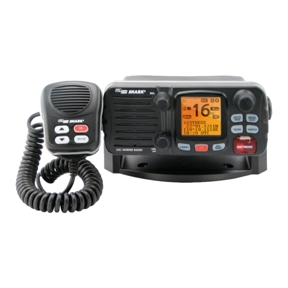
- Page 6 1. DESCRIZIONE DEL DISPOSITIVO 1.1 Introduzione Congratulazioni per aver acquistato il ricetrasmettitore marino Polmar Shark2, stazione radio VHF DSC con una potenza in uscita di 25/1 Watt, da alimentare a 12V cc. La radio supporta la funzione DSC (Digital Selective Calling) in classe D tramite un’unità...
- Page 7 2. COMANDI E SCHERMO LCD 2.1 Pannello frontale Volume e ON/OFF Manopola con rotazione da 0 a 270°. Girare in senso orario per accendere il dispositivo. Poi continuare a girare fino a raggiungere il livello audio desiderato. Squelch Utilizzare questo selettore per impostare la soglia dello squelch (eliminazione del rumore di fondo).
- Page 8 Si usa questo tasto per accedere alle impostazioni DSC/ Menu del menu o alla modalità DSC. La modalità menu si usa per impostare la radio. Premendo e rilasciando il tasto HI/LO si passa dalla Hi /Low/ Mem potenza alta di 25 Watt a quella bassa di 1 Watt. Sullo schermo vengono visualizzate le icone pure per indicare la selezione effettuata.
- Page 9 2.2 Pannello posteriore 1 Connettore dell’antenna Collegare un’antenna appropriata al vostro VHF per garantire una comunicazione soddisfacente. Fornire all’apparecchio radio un’alimentazione 2 Alimentazione di 12Vcc. Se necessario, è possibile collegare un alto- 3 Cavo connettore parlante esterno. dell’altoparlante esterno Collegando la radio ad un ricevitore GPS è 4 Connettore del GPS possibile acquisire la posizione dell’imbarca- zione e l’ora attuale.
- Page 10 Microfono Canale Su/Giù Premendolo e rilasciandolo si cambia canale. Premendo il tasto 16 si abbandona qualsiasi mo- Tasto 16 dalità e si attiva il canale di emergenza. Premendo e rilasciando il tasto HI/LO si passa Hi /Low dalla potenza alta di 25 Watt a quella bassa di 1 Watt.
- Page 11 SCHERMO LCD...
- Page 12 3. INSTALLAZIONE 3.1 Accessori forniti L’apparecchio è dotato degli accessori seguenti: 1. Staffa di fissaggio a snodo (1 pz.) 2. Cavo di alimentazione (1 pz.) 3. Manopole di fissaggio (2 pz.) 4. Staffa a muro (1 pz.) 5. Viti autofilettanti per il fissaggio della staffa (4 pz.) 6.
- Page 13 • I comandi del pannello frontale siano facilmente accessibili; • Sia consentito il collegamento del cavo d’alimentazione e dell’antenna; • Ci sia spazio a sufficienza per poter agganciare il microfono a fianco; • L’antenna deve essere montata almeno a 1 m dalla radio. 3.3 Connessioni ALIMENTAZIONE La radio deve essere alimentata a 12Vcc.
- Page 14 ANTENNA Un’antenna adeguata è l’elemento più importante per ottenere la migliore prestazione di ogni sistema di comunicazione. Consultare il proprio rivenditore di antenne autorizzato per richiedere assistenza nel montaggio della radio. Ricevitore GPS Cassa esterna Coperchio Giallo Verde Impermeabile Fusibile Nero Rosso Batteria...
- Page 15 6. Montare il pannello frontale sulla staffa facendo collimare le protuberan- ze laterali della staffa con le due fessure ai lati del pannello frontale (tali fessure sui lati della radio consentono la regolazione della direzione dello schermo per una facile lettura e utilizzo , 15° per ogni rotazione per un totale di 45°...
- Page 16 Per cambiare l’angolo d’inclinazione dopo l’installazione: 1. Allentare le manopole laterali della staffa di fissaggio; 2. Regolare il pannello frontale nella direzione desiderata facendo combacia- re le protuberanze interne della staffa con le fessure laterali esterne del pannello frontale; 3. Serrare nuovamente le manopole. 3.5 Installazione dell’antenna / esposizione EMC Per ottenere una prestazione ottimale della radio e nel contempo ridurre al minimo l’esposizione fisica alle frequenze elettromagnetiche della radio, assi-...
- Page 17 4. FUNZIONI DI BASE 4.1 Trasmissione e ricezione ATTENZIONE: La trasmissione senza antenna potrebbe danneggiare la radio. 1. Dopo aver installato la radio, assicurarsi che il cavo di alimentazione e l’antenna siano connessi correttamente. 2. Ruotare la manopola di accensione/volume in senso orario per accende- re la radio ed impostare un volume confortevole.
- Page 18 4.2.2 Modalità memo (FAV) Premere e tener premuto il tasto HI/LO/MEM nella modalità normale di ope- razione per attivare la modalità MEM. L’icona appare sullo schermo. Ruotare il selettore CH nella modalità MEM: in questo modo, solo i canali che sono stati salvati nella memoria sono visualizzati, in modo da agevolare la sele- zione dei canali senza dover scorrere canali non desiderati durante la scansione.
- Page 19 4.5 Scan (Scansione) La scansione è un modo efficace per localizzare velocemente i segnali entro una vasta gamma di frequenze. Il trasmettitore ha 4 modalità di scansione disponibili: scansione normale, scansione memoria canali, scansione prioritaria e scansione prioritaria memo- ria canali. La modalità di default è scansione normale (1, 2, 3, 4...). Per passare in modalità...
- Page 20 5 CHIAMATE SELETTIVE DIGITALI (DSC) 5.1 Generalità La chiamata selettiva digitale (DSC) è un metodo semi automatico per stabi- lire un collegamento radio ed è stato concepito dall’Organizzazione Marittima Internazionale (IMO) come standard internazionale per comunicazioni radio in modalità VHF, MF e HF. È stata concepita, inoltre, in parte dal Sistema di Soccorso e Sicurezza Marittimo Globale (GMDSS).
- Page 21 TIPO DI CHIAMATA DESCRIZIONE Last Call Richiama l’ultima chiamata ricevuta, indipendente- mente dal tipo di chiamata. (Ultima Chiamata) New Call Effettua una nuova chiamata inserendo il codice MMSI o selezionando la chiamata dalla rubrica (mas- (Nuova Chiamata) simo 20 nomi di imbarcazioni) Group (Gruppo) Invia la chiamata a tutte le radio impostate nello stesso gruppo MMSI.
- Page 22 5.2.1 Invio di una chiamata “INDIVIDUALE” E’ possibile inviare una chiamata individuale sia ad un’altra imbarcazione che ad una stazione costiera. 5.2.1.1 Invio di una chiamata individuale (codice MMSI memorizzato nella rubrica) Premere brevemente il tasto CALL in modo standby, la radio entrerà nel menu chiamata ed eseguirà...
- Page 23 5.2.2 Invio di una Chiamata di Gruppo (“GROUP”) 5. 2. 2 S E N D A G R O U P C A L L 5. 2. 2 S E N D A G R O U P C A L L Premere brevemente il tasto DSC/MENU per accedere al menu di chiamata, Short press DSC/MENU key enter the call item use below process Short press DSC/MENU key enter the call item use below process...
- Page 24 5.2.4 Invio di una Chiamata di Richiesta Posizione Questa opzione consente di richiedere le informazioni di posizione GPS a qual- siasi imbarcazione per il quale si conosce l’indirizzo MMSI. 1. Selezionare la funzione “POS REQUEST” sul menu DSC, premere la mano- pola CH per richiamare la rubrica, selezionare il codice MMSI dell’imbarca- zione della quale si desidera conoscere le informazioni di posizione.
- Page 25 5.2.6 Ultima chiamata (richiamo dell’ultima chiamata ricevuta) Questa funzione è utile e frequentemente utilizzata per effettuare chiamate individuali. 1. Premere brevemente il tasto DSC/ Menu per accedere al menu DSC e se- lezionare LAST CALL, premere la manopola CH per visualizzare i dettagli dell’ultima chiamata ricevuta.
- Page 26 E’ prevista la risposta al chiamante mediante l’invio di una conferma (“acknowledgement”) o di un cambio canale (“change the channel”) oppure mancata conferma (“unable ACK”). Potete premere il tasto ENT per visualiz- zare le opzioni possibili tra: “ACK” o ”change channel” oppure ”unable ACK” che appariranno sul display, ruotare la manopola CH per selezionare la vostra scelta e premere ENT per inviarla al corrispondente.
- Page 27 2) INDIV REPL Y set to MANUAL AUTO SW OFF INDIVIDUAL ENT OPTION CH08 REQUEST SAFETY FROM INDIVIDUAL AUTO SW OFF KEY SILENCE ENT OPTION 987654321 14:20 UTC CH08 REQUEST CANCEL EXIT SAFETY FROM KEY SILENCE 00:04 00:05 00:06 987654321 14:20 UTC CANCEL EXIT...
- Page 28 Per le chiamate di “routine” 5.3 Ricezione di una chiamata di gruppo “GROUP” Una chiamata di Gruppo “GROUP” è ricevuta da chiunque presente nel gruppo pre-impostato. Un avviso acustico di chiamata e l’icona DSC lampeggiante sul display avviseranno l’operatore – in modo simile alla chiamata individuale “INDIVIDUAL”.
- Page 29 5.3.1 Ricezione di una chiamata “ALL SHIPS” Quando si riceve una chiamata “ALL SHIPS” da altre imbarcazioni o dalla sta- zioni costiere, se ci si trova nel raggio di comunicazioni del trasmettitore VHF, la radio emette un avviso acustico e l’icona DSC lampeggia. Il segnale acustico è...
- Page 30 2) AUT O SW set to OFF (rotate the CH knob to view the whole information of received call ALL SHIPS AUTO SW OFF ENT ACCEPT SAFETY FROM REQUEST KEY SILENCE 5.3.2 Ricezione e risposta ad una chiamata di prova (TEST) 987654321 CANCEL EXIT...
- Page 31 1. Funzione LL reply impostata su manuale (MANUAL) 1) LL reply set to MANUAL ENT ACK POSITION REQUEST FROM ENT ACK KEY SILENCE KEY SILENCE 987654321 CANCEL EXIT 00:01 00:02 00:03 2) LL reply set to AUT O 2. Funzione LL reply impostata su automatico (AUTO) Con questa funzione impostata su AUTO il chiamante sarà...
- Page 32 5.3.5 Receiving a geographic area call A GEOGRAPHIC AREA CALL are received by vessels by within a specific geographical boundary area. 1. When you receive notification of a geographical call press any key to cancel the alert. The radio tunes to the disgnated channel by press ENT key or CANCEL key to normal mode with original channel.
- Page 33 chiamata precedente. Se la chiamata a bassa priorità interrompe l’allarme della chiamata precedente, l’avviso acustico della chiamata precedente ripartirà. Dopo che la procedura automatica (ad eccezione della procedura auto- matica di Emergenza (DISTR) è terminate sia da parte dell’operatore che dal timeout automatico, la radio automaticamente visualizzerà...
- Page 34 alta potenza con la stazione connessa. DISTRES CALL DISTRES CALL 8. Se nessuna conferma è ricevuta (no ACK), la radio trasmetterà nuovamente DISTRES CALL UNDEFINED SENT WAIT la chiamata di Emergenza ad intervalli casuali di 3.5 o 4.5 minuti finchè non UNDEFINED HOLD DISTRES ENT OPTION...
- Page 35 DISTRES CALL OPTION SEND CANCEL SENT WAIT PAUSE ENT OPTION CANCEL RESEND: 03:58 RESEND: 03:50 RESEND: 03:50 Press ENT to enter the option select cancel and press ENT press ENT to send DISTRES CALL OPTION SEND CANCEL NOTA: premere il tasto ENT e selezionare l’opzione per inviare la cancellazione SENT WAIT PAUSE dell’Emergenza (DISTR)
- Page 36 terà una segnalazione acustica ed il display indicherà quanto sotto riportato. 5.4.2.3 RRECEIVING A DISTRESS CANCEL Restare in ascolto sul canale 16 in attesa per prestare assistenza. DISTRESS DISTRESS CANCEL FROM CANCEL FROM 987654321 5.4.2.3 987654321 RRECEIVING A DISTRESS CANCEL 5.4.2.3 RRECEIVING A DISTRESS CANCEL...
- Page 37 6 MENU IMPOSTAZIONI 6.1 Descrizione funzioni del menu Le funzioni di impostazione della radio sono accessibili tramite la modalità menu, che contiene le seguenti selezioni: VOCE DESCRIZIONE Buddy List Seleziona la rubrica per inserire nomi e codici MMSI per chiamate frequenti verso stazioni DSC. Si possono me- (Lista Contatti) morizzare fino a 20 nominativi.
- Page 38 6.2 Utilizzo del menu impostazioni Per accedere alla modalità menu, tenere premuto il tasto MENU/DSC; compa- re l’area di testo con la lista del “SET UP MENU” (menu impostazioni). Per uscire dalla modalità menu, premere il tasto 16/9 oppure CANCEL, oppure selezionare l’opzione EXIT dal menu.
- Page 39 6.3.3 Cancellare un contatto 1. Selezionare il contatto che si vuole cancellare dalla lista. 2. Ruotare la manopola CH per selezionare l’opzione “DELETE” (cancella). 3. Tenere premuta la manopola CH per confermare la cancellazione. 4. Il contatto selezionato sarà rimosso e ritorna sulla pagina della rubrica. 5.
- Page 40 6.7 GPS/Ora La radio percepisce automaticamente i codici NMEA e ne decodifica latitudine, longitudine, posizione e orario. Se il ricevitore GPS di navigazione non è colle- gato o non funziona, si dovrebbe inserire una posizione manuale di latitudine e longitudine e UTC, ed usarli nel messaggio di pericolo trasmesso in DSC. Se le informazioni LAT/LONG decodificate sono valide, i dati si visualizzano sullo schermo;...
- Page 41 1. Selezionare “GPS/TIME” (GPS/ora), poi “SETTINGS” (impostazioni), poi “POS DISPLY” (visualizzazione posizione). 2. Selezionare “ON” oppure “OFF”. Scegliendo ON, il display indica la posizione dell’imbarcazione. Nell’esempio successivo viene visualizzata la selezione ON. SETTINGS POS DISPLY DISTRESS >POS DISPLY 27°34.1268 N TIME DISPLY >...
- Page 42 6.7.2.5 Opzioni di visualizzazione rotta/velocità (COG/SOG) Si può scegliere se abilitare la visualizzazione della rotta (COG) e della velo- cità (SOG) sullo schermo. Se è già visualizzata l’ora, COG/SOG scompaiono automaticamente, poiché condividono la stessa riga sullo schermo. DISTRESS COG/SOG 27°34.1268 N >ON 82°55.5587 W...
- Page 43 6.8.1.2 Modifica nome canale 1. Selezionare “RADIO SETUP” (impostazione radio), poi “CH NAME” (nome cana- le) e infine “CH INFO” (informazioni canale). Selezionare il nome del canale de- siderato ruotando la manopola CH, quindi premere la manopola stessa: il display mostra il nome del canale oltre che “EDIT”...
- Page 44 6.9 Impostazione DSC Il sottomenu DSC SETUP (impostazione DSC) permette di impostare gli attri- buti della funzione DSC/ATIS. Le 7 voci seguenti sono disponibili: User MMSI (MMSI Utente) Group Setup (Impostazione Gruppo) ATIS MMSI (MMSI ATIS) ATIS ENABLE (Abilitazione ATIS) INDIV REPLY (Risposta posizione) DSC ENABLE (Risposta posizione) POS REPLY (Risposta posizione)
- Page 45 6.9.2 Gestione dei gruppi di MMSI Si possono programmare sino a tre gruppi di MMSI con relativo nome e codice di identificazione; i codici di identificazione devono sempre iniziare con uno zero (0): occorre pertanto immettere solo le ultime 8 cifre del codice di iden- tificazione (lo “0”...
- Page 46 6.9.3 Immettere il proprio ATIS MMSI Si tratta di un’operazione da eseguire un’unica volta. Dopo aver immesso il proprio ATIS MMSI, sarà possibile accedere alle funzioni ATIS. 1. Selezionare “DSC SETUP” (impostazione DSC), poi “ATIS MMSI” e premere la manopola CH. Se un codice MMSI esistente è memorizzato, questo ap- pare sullo schermo.
- Page 47 6.9.5 INDIV REPLY L’utente potrà utilizzare questa funzione per regolare la risposta in manuale o in automatico: MANUAL ACK e cambiare il canale scelto da chi invia. DSC SETUP INDIV REPLY INDIV REPLY MANUAL AUTOMATIC DSC ENABLE POS REPLY DSC SETUP INDIV REPLY INDIV REPLY MANUAL...
- Page 48 6.9.9 Risposta alla chiamata di prova Abilitazione della risposta automatica alla chiamata di prova. Quando abili- tata, la chiamata di prova riceverà una risposta automatica allo scadere del timer “auto reply”. DSC SETUP TEST REPLY POS REPLY MANUAL AUTO SWITCH AUTO TEST REPLY 6.9.10 Timeout...
- Page 49 7 MANUTENZIONE La radio marina VHF è resistente all’acqua e soddisfa il requisito della normativa giapponese JIS livello 7. Assicura buona affidabilità nelle varie circostanze in mare. È studiata per essere priva di manutenzione. Per conservarla in buona condi- zione di funzionamento: •...
- Page 50 8 SPECIFICHE Frequenza TX: 156.025 ~ 157.425 MHz Frequenza RX: 156.375 ~ 162.000 MHz Canali: Canali Internazionali Tipo di modulazione: Impedenza antenna: 50 Ohm Microfono: tipo condensatore Alimentazione: 12 Vcc Assorbimenti (nominali a 12Vcc) Trasmissione a 25W: 5A Ricezione max audio: 1.5A Ricezione in stand-by: 0,25A Sensibilità...
- Page 52 TABELLA DELLE FREQUENZE FREQUENZA (MHz) MODALITà NOTE 156.050 160.650 156.100 160.700 156.150 160.750 156.200 160.800 156.250 160.850 156.300 156.300 1W ATIS 156.350 160.950 156.400 156.400 1W ATIS 156.450 156.450 156.500 156.500 1W ATIS 156.550 156.550 1W ATIS 156.600 156.600 1W ATIS 156.650 156.650 1W ATIS...
- Page 53 156.525 156.525 solo DSC 156.575 156.575 1W ATIS 156.625 156.625 1W ATIS 156.675 156.675 156.725 156.725 1W ATIS 156.775 156.775 156.825 156.825 156.875 156.875 1W ATIS 156.925 161.525 156.975 161.575 157.025 161.625 157.075 161.675 157.125 161.725 157.175 161.775 157.225 161.825 157.275 161.875 157.325...
- Page 54 Unauthorized changes or modifications to this equipment may void compli- ance with ETSI Rule. Any changes or modification must approved in writing by Polmar. This equipment has been tested and licensed to comply with the limits for Class D Digital Marine Devices.
-
Page 55: Table Of Contents
TAblE Of cONTENTs 1 EquIPmENT dEscRIPTION 1.1 Introduction 1.2 ETSI information 2 cONTROls ANd lcd dIsPlAy 2.1 Base station panel 2.2 Base station panel (rear) 2.3 Handset 2.4 Liquid crystal display 3 INsTAllATION 3.1 Supplied accessories 3.2 Location 3.3 Connections 3.4 Mounting the radio 3.5 Antenna mouting/the EME exposure 3.6 Mounting the handset... - Page 56 5.2.1.2 Manually sending an Individual Call 5.2.1.3 Retrying a Routine Call 5.2.2 Send a “group” call 5.2.3 Send an “all ships” call 5.2.4 Send a position request call 5.2.5 Send a DSC test call 5.2.6 Last call (recall the most recent incoming call) 5.2.7 Send an individual call using the call log 5.2.8 Send an individual call using the distress log 5.2.9 Receiving and ACk an “individual”...
- Page 57 6.6 Local/distant 6.7 GPS/time 6.7.1 Manual entry GPS date 6.7.2 Settings 6.7.2.1 Position display on/off 6.7.2.2 Time display on/off 6.7.2.3 Local time (time offset) 6.7.2.4 Time format options (Time Format) 6.7.2.5 Course/speed display options (COG/SOG) 6.7.2.6 GPS alert 6.8 Radio setup 6.8.1 Channel name display and editing 6.8.1.1 Channel name display 6.8.1.2 Channel name editing...
-
Page 58: Equipment Description
1 EquIPmENT dEscRIPTION 1.1 introduction Congratulations on your purchase of Polmar marine band radio. Shark2 is a VHF DSC Base Station Radio with output power of 25/1 watt. It should be powered by a 12VDC power supply. The radio can support DSC (Digital Selective Calling) operation with specially designed DSC unit. -
Page 59: Controls And Lcd Display
cONTROls ANd lcd dIsPlAy base station panel Volume and 0-270° rotary control knob. Turn clockwise to power Power On/Off on. Continue to turn until a comfortable audio level. Use this knob to set the squelch threshold, which cuts Squelch off the receiver when the signal is too week for recep- tion of anything but noise. - Page 60 DSC/ Menu Use this knob to enter Menu Setup or DSC Call Menu Call Mode is used for making DSC Calls. Menu Mode is used to setup the radio. Hi /Low/ Mem Press and release HI/LO button to toggle between 25 watt power output and 1 watt output.
-
Page 61: Base Station Panel (Rear)
2.2 base station (Rear) Antenna Socket Connect a suitable antenna to your marine VHF radio to get a satisfying communication. Connect the radio to a 12 VDC power source. Power Source External Speaker Jack If need be, you can also use this cable to con- nect an external speaker. -
Page 62: Handset
2.3 Handset Channel Up/ Down Press and release to change channel. Press and release 16 key to select channel 16 16 button first; Press 16 key to quit all other modes and to into the priority channel. Hi /Low Hi/Low Press and release HI/lO button to tog- gle between 25 watt power output and 1 Watt output. -
Page 63: Liquid Crystal Display
2.4 lcd display... -
Page 64: Installation
3 INsTAllATION 3.1 supplied accessories Manufacturer supplies you the following accessories as soon as you purchase this marine radio. 1 Mounting Gimbal (1 pc) 2 Power Supply Cable (1 set) 3 Mounting knob (2 pcs) 4 Wall Hanger (1 pc) 5 Self-tapping Screw for Fixing Mounting Gimbal (4 pcs) 6 Flat Screw for Fixing Mounting Gimbal (4 pcs) 7 Plain Washer (4 pcs) -
Page 65: Connections
• Provides accessibility to the front panel controls; • Allows connection to a power supply and an antenna; • Has free space nearby for installation of a handset hanger; • Where the antenna can be mounted at least 3 feet from radio 3.3 connections POWER SUPPLY You radio should be powered by a 12VDC power supply. -
Page 66: Mounting The Radio
ANTENNA A very important part for the performance of any communication system is a suitable antenna. Consult your dealer about antennas and ask them to help to mount your radio. GPS Navigation receiver External speaker Green Yellow Waterproof Deck outlet Fuse Black 3.4 mounting the radio... - Page 67 5. Mount the base station onto the bracket with notice of the matching of the protuberances on the both inner side of the bracket and the pits on the two sides of the base station (the selectable pits on the sides of the radio allow you adjust the direction of the radio face to satisfy your easy-to- read-and-use, 150 for each rotation and totally 450 tolerance);...
-
Page 68: Antenna Mouting/The Eme Exposure
8. Change the angle after installation: Loosen the mounting knob at the sides of gimbal first. Then adjust the base station to an appropriate direction with matching of the protuberances on the inner sides of gimbal and pits on the outer sides of base station. -
Page 69: Basic Operation
4 bAsIc OPERATION 4.1 Transmission and reception 1. CAUTION: Transmitting without an antenna may damage the radio. 2. After the radio has been installed, make sure of the power supply and antenna being properly connected. 3. To rotate the VOLUME/POWER knob clockwise turn on the radio and se- lect a comfortable volume level. -
Page 70: Memo (Fav) Mode
4.2.2 memo (fAv) mode Press and hold the HI/lO/mEmO button while in normal operation mode to enter Mem mode, icon indicator appears on LCD. On the Mem Mode rotate the CH knob displays only the channels that you have saved to memory, which enables you to easily use your favorite channels while bypassing unwanted or seldom- used channels during a scan. -
Page 71: Scan
4.5 scan Scanning is an efficient way to locate signals quickly over a wide frequency range. The transceiver has 4 Scan mode available: All scan, FAV CH scan, Priority scan, Priority FAV CH scan. Default is normal all scan(1.2.3.4……) 1. Press and hold scAN key over 3 sec, the Priority scan icon (1, 16, 2, 16, 3, 16…) will be selected. -
Page 72: Digital Selective Calling
5 dIGITAl sElEcTIvE cAllING 5.1 General DSC(Digital Selective Calling) is a semi-automated method of establishing a radio call, it has been designated by the International Maritime Organization (IMO) as an international standard for establishing VHF, MF and HF radio calls. It had also been designated part of the Global Maritime Distress and Safety System (GMDSS). - Page 73 dEscRIPTION cAll TyPE last call Recall last call no matter what type of call received at last. New call Make a new call, by inputting the MMSI or pick up from the list max 20 Buddy names. Group Sends transmissions that are only received by radios that share a common group MMSI number, up to 3 group MMSI numbers can be stored and call.
-
Page 74: Sending An"Individual"Call
5.2.1 sENdING AN “INdIvIduAl” cAll You can SEND an individual call, either to a ship or to a boast station. 5.2.1.1 sending an individual call (mmsI stored in buddy list) Short press call key at the standby mode, radio will enter the call menu and the process of send INDIVI call please see below procedure. -
Page 75: Send A "Group" Call
SEND AGAIN 5.2.2 sENd A “GROuP” cAll 5. 2. 2 S E N D A G R O U P C A L L Short press DSC/MENU key, enter the call item, use below process to send a 5. 2. 2 S E N D A G R O U P C A L L Short press DSC/MENU key enter the call item use below process group call. -
Page 76: Send A Position Request Call
5.2.4 send a position request call The option enables you to request GPS position information from any vessel for which an MMSI number is known. 1. Select the POS REQUEST on the DSC Menu, press the CH knob to enter the buddy list, select the one for position information. -
Page 77: Last Call (Recall The Most Recent Incoming Call)
5.2.6 last call (recall the most recent incoming call) This facility also is useful and is used frequently as routing individual call 1. Short press the DSC/ Menu key to enter the DSC mode LAST CALL will be pointed, press CH knob to display the detail information of the last call. 2. - Page 78 To cancel the mode, press the CANCEL key. The call is interrupted and the Nor- mal Communication screen appears in the display with the channel remaining. Also press CANCEL kEY can terminate the auto ACk and auto switch before 10s when received call and If INDIV reply set to AUTO, but you not want radio switch to new channel.
-
Page 79: Receiving A "Group" Call
for routine call 5.3 Receiving a “Group” call A GROUP CALL is received from anyone in your prearranged group. A friendly Call Alarm sounds along with a flashing DSC ICON – similar to INDIVIDUAL call operation. The transceiver automatically tunes to the channel designated in the DSC signal. -
Page 80: Receiving And Reply A "Test" Call
There is no need to send back an “acknowledgement” to the caller. You may initiate establish voice communication after press ENT to switch to sender desire Channel. Establish voice communication on the channel selected by the caller. The MMSI data contained within the received DSC signal is displayed in the LCD. - Page 81 1) Test reply set to manual (rotate the cH knob to view the whole information of received call) AUTO ACK ENT ACK TEST IS OFF KEY SILENCE CALL FROM AUTO ACK ENT ACK TEST AUTO ACK ENT ACK TEST 11:1 0UTC CANCEL EXIT 987654321...
-
Page 82: Receiving A "Position Reply" Call
3) ll reply set to Off 3) LL reply set to OFF 3) LL reply set to OFF POSITION LL REPLY OFF KEY SILENCE REQUEST FROM POSITION LL REPLY OFF 3) LL reply set to OFF CANCEL EXIT REQUEST FROM KEY SILENCE CANCEL EXIT POSITION... -
Page 83: Distress Auto Procedure
3) LL reply set to OFF NEW CALL NEW CALL ACCEPT POSITION LL REPLY OFF ACCEPT REQUEST FROM KEY SILENCE CANCEL EXIT At the same time, the unread icon will flash, if you select “YES”,radio will display the new call content and the unread icon will disappear. If you se- 5.3.4 Receiving a Position Reply call... -
Page 84: Resend The Distress Auto Procedure
busy. Distress call is sent from channel 70 should delay 1s, When Distress is DISTRES CALL DISTRES CALL DISTRES CALL DISTRES CALL DISTRES CALL DISTRES CALL sent, the acoustic alarm goes to 2s ,and screen will display same as below: UNDEFINED SENT WAIT UNDEFINED... -
Page 85: Receiving Distress Auto Procedure
DISTRES CALL OPTION SEND CANCEL DISTRES CALL OPTION SEND CANCEL DISTRES CALL OPTION SEND CANCEL SENT WAIT PAUSE SENT WAIT PAUSE DISTRES CALL OPTION SEND CANCEL SENT WAIT PAUSE ENT OPTION ENT OPTION SENT WAIT PAUSE CANCEL CANCEL ENT OPTION CANCEL RESEND: 03:58 RESEND: 03:50... -
Page 86: Receiving A Distress Cancel
5.4.2.3 Receiving a distress cancel 5.4.2.3 5.4.2.3 RRECEIVING RRECEIVING A DISTRESS CANCEL A DISTRESS CANCEL 5.4.2.3 RRECEIVING A DISTRESS CANCEL DISTRESS DISTRESS DISTRESS DISTRESS DISTRESS DISTRESS CANCEL FROM CANCEL FROM CANCEL FROM CANCEL FROM CANCEL FROM CANCEL FROM 987654321 987654321 987654321 987654321 987654321... -
Page 87: Setup Menu
6 sETuP mENu 6.1 menu function description The radio’s setup functions are accessed through the Menu mode. Menu mode selections are as follows. ITEm dEscRIPTION buddy list Selects the Buddy List Entry routine to enter Names and MMSI’s for frequently called DSC stations. Up to 20 names could be stored. -
Page 88: Set-Up Menu Navigation
6.2 set-up menu navigation To access the Menu Mode: Press the 16 or CANCEL key or else select the EXIT option from the menu. Rotate the CH knob to select the Item within the Set-Up Menu list To confirm a selected item for adjustment, push the CH knob. When the desired setting is done, press the CH knob to enter the setting, and move back to the Main Menu list. -
Page 89: Delete An Entry
6.3.3 delete an entry 1. Select the one which you want to delete from the list. 2. Rotated the CH knob to select the Delete option. 3. Press and hold the CH knob to confirm the delete action. 4. The selected record will be removed and go back to BUDDY list page. You can repeat steps from 1 to 4 to delete more records, or press cancel to exit. -
Page 90: Gps/Time
6.7 GPs/TImE The radio automatically detects NMEA strings and decodes appropriate lati- tude/longitude position and time. If the GPS navigation receiver is not con- nected on or is not functional, a manual latitude/longitude position and UTC should be entered and used in the DSC distress transmitted message. When valid Lat/Lon information is detected, the data is display on the LCD, when there is no valid position information, NO GPS INFORMAT ION appears. -
Page 91: Time Display On/Off
1. Select GPS/TIME then SETTINGS, then POS DISPLY. 2. Select ON (on) or OFF (off) as desired, this is example, selected on and the screen shows the vessel position. sETTINGs POs dIsPlAy dIsTREss >POs dIsPlAy > ON 27°34.1268 N TImE dIsPlAy 82°55.5587 W TImE OffsET 356°12.6Kts... -
Page 92: Course/Speed Display Options (Cog/Sog)
6.7.2.5 course/speed display options (cOG/sOG) You can enable COG (Course over Ground) and SOG (Speed over Ground) displayed on normal mode. If the TIME DISPLAY is turn ON, COG/SOG will be turned off automatically since it share the same bottom line for display. dIsTREss cOG/sOG 27°34.1268 N... -
Page 93: Channel Name Editing
6.8.1.2 channel name editing 1. Select RADIO SETUP then CH NAME, then CH INFO, Select the desired channel name by rotate CH knob and then press the CH knob the screen shows the channel name and EDIT and DELETE. 2. Select EDIT and press the CH knob to edit the existing name tag, Input the new name over the existing name and press the CH knob to display the YES/NO conformation 3. -
Page 94: Dsc Setup
6.9 dsc setup The submenu is used to set behavior of the DSC/ATIS function. The following 6 items are available for selection. user mmsI Group setup ATIs mmsI ATIs ENAblE INdIv REPly dsc ENAblE POs REPly AuTO sWITcH TEsT REPly TImE OuT 6.9.1 Enter your user mmsI (user mmIs) This is a once-only operation. -
Page 95: Maintain Groups
6.9.2 maintain groups You can program up to three group MMSI numbers and associated Group names, group MMSI numbers always begin with a zero (0). You only enter the last 8digits of the group ID number, the intial “0” is automatically entered. 6.9.2.1 Enter your groups 1. -
Page 96: Atis Mmsi
6.9.3 Enter your ATIs mmsI This is a once-only operation. You must enter your ATIS MMSI first then you can access the ATIS functions. Select DSC SETUP then ATIS MMSI and press the CH knob. If an existing MMSI is stored, the –values appear. 1. -
Page 97: Indiv Reply
6.9.5 INdIv REPly User can use this function to set the individual reply to MANUAL or AUTO. MANUAL: MANUAL ACk and switch to sender desired channel AUTO: AUTO ACk and switch to sender desired channel DSC SETUP INDIV REPLY MANUAL INDIV REPLY DSC ENABLE AUTOMATIC... -
Page 98: Test Reply
6.9.9 Test Reply To enable the automatically reply for test call. When enabled, the test call will be automatically reply when ‘auto reply’ time reach. DSC SETUP TEST REPLY POS REPLY MANUAL AUTO SWITCH AUTO TEST REPLY 6.9.10 Timeout RETURN TO There is 3 timeout in the DSC menu, namely: NORMAL MODE •... -
Page 99: Maintenance
7 mAINTENANcE Your VHF Marine Radio is a marine radio of water proof who can meet the require- ment of JIS level 7, gives you a good reliability when using in marine circumstance. The equipment is designed to be maintenance free. To keep your radio in good working condition: •... -
Page 100: Specification
8 sPEcIfIcATIONs TX Frequency 156.025 ~ 157.425 MHz RX Frequency: 156.375 ~ 162.000 MHz Channels INT Channels Modulation type Antenna impedance 50 Ohm Microphone condenser type Power supply 12 VDC Current drain (12Vdc nominal) Trasmission at 25W: 5A Receiving at max audio: 1.5A Receiving stand-by: 0,25A Sensitivity at 12dB Sinad 0.25 µV... -
Page 101: Frequencies Chart
9 fREquENcIEs cHART FREQUENCY (MHz) MODE NOTE 156.050 160.650 156.100 160.700 156.150 160.750 156.200 160.800 156.250 160.850 156.300 156.300 1W ATIS 156.350 160.950 156.400 156.400 1W ATIS 156.450 156.450 156.500 156.500 1W ATIS 156.550 156.550 1W ATIS 156.600 156.600 1W ATIS 156.650 156.650 1W ATIS... - Page 102 156.525 156.525 solo DSC 156.575 156.575 1W ATIS 156.625 156.625 1W ATIS 156.675 156.675 156.725 156.725 1W ATIS 156.775 156.775 156.825 156.825 156.875 156.875 1W ATIS 156.925 161.525 156.975 161.575 157.025 161.625 157.075 161.675 157.125 161.725 157.175 161.775 157.225 161.825 157.275 161.875 157.325...
- Page 103 PREcAuZIONI • NON collegare il ricetrasmettitore ad una sorgente di alimentazione ca: potrebbe danneggiarsi seriamente. • ATTENZIONE - Durante la trasmissione evitare di toccare l’antenna o il con- nettore di antenna. • NON collegare l’apparato a sorgenti di alimentazione DC con tensione supe- riore ai 16V.
- Page 105 Hereby Polmar srl, declares that this apparatus brand Polmar, mod. Shark2 is in compliance with the essential requirements and other relevant provisions of Directive 1999/5/CE. Por medio de la presente Polmar srl declara que el Polmar Shark2 cumple con los requisitos y cuales- quiera otras disposiciones aplicables o exigibles de la Directiva 1999/5/CE.
- Page 106 INfORmAZIONE AGlI uTENTI Ai sensi dell’art. 13 del decreto legislativo 25 luglio 2005, n. 15”Attuazione delle Direttive 2002/95/CE, 2002/96/CE e 2003/108/CE, relative alla riduzione dell’uso di sostanze peri- colose nelle apparecchiature elettriche ed elettroniche, nonché allo smaltimento dei rifiuti” Il simbolo del cassonetto barrato riportato sull’apparecchiatura indica che il prodotto alla fine della propria vita utile deve essere raccolto separatamente dagli altri rifiuti.
- Page 108 Importato e distribuito da Polmar srl info@polmar.biz • www.polmar.biz...
Need help?
Do you have a question about the Shark2 and is the answer not in the manual?
Questions and answers