
Related Manuals for POLMAR DB-50M


Summary of Contents for POLMAR DB-50M
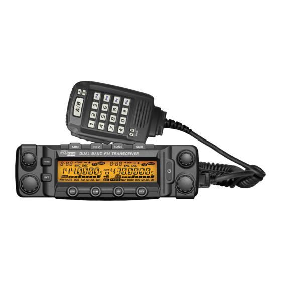
- Page 1 DUaL BaND VHF/UHF DUaL BaND VHF/UHF traNsceIVer Manuale d’uso User’s manual Importato e distribuito da Polmar srl...
- Page 2 Guscio elegante, robusto e stabile, funzionalità evolute ed affidabili, perfetto e di valore. Conforme . Ricetrasmettitore biban- da particolarmente indicato per uso veicolare, in linea con la filosofia Aziendale di innovazione. Prima di programmare il ricetrasmettitore, leggete questo manuale, poi potete impostare parametri quali: frequenza, codi- ficazione, ...
-
Page 3: Prefazione
Se avvertite odore o fumo prove- le potenzialità di questo ricetrasmettitore. niente dal ricetrasmettitore, spegnetelo immediatamente. Chie- dete assistenza ad un centro Polmar o al vostro Rivenditore. Non trasmettete a piena potenza per periodi prolungati, il ri- cetrasmettitore potrebbe surriscaldarsi. -
Page 4: Table Of Contents
sommario Prefazione Trasmettere toni DTMF Nuove ed innovative funzionalità Commutazione potenza alta / media / bassa Accessori forniti Inversione di frequenza Accessori opzionali Selezione larghezza di banda Approntamento all’uso Canale HOME Installazione veicolare Canale memoria Cavo alimentazione in cc Doppio ascolto Sostituzione fusibili Allarme emergenza Antenna... - Page 5 Impostazione modalità squelch Retroilluminazione LCD Compressore / espansore Luminosità retroilluminazione tasti Nota di chiamata Registrazione chiamate Impostazione modalità tastiera Funzionalità AM Blocco tastiera Funzionalità AM automatica TX OFF (blocco PTT) Presa altoparlante esterno Impostazione livello squelch Regolazione volume cicalino Inversione frequenza Collegamento in diretta Impostazione silenziamento banda secondaria Microaltoparlante...
-
Page 6: Nuove Ed Innovative Funzionalità
Nuove ed innovative funzionalità Questo ricetrasmettitore bibanda contenuto in un guscio elegante, robusto e stabile, vanta funzionalità evolute ed affidabili, perfetto e di valore. Particolarmente indicato per uso veicolare, in linea con la filosofia Aziendale di innovazione. Ecco i punti caratteristici rilevanti. •... -
Page 7: Accessori Forniti
accessori forniti Dopo aver estratto il contenuto dall’imballo, verificate la presenza delle parti in dotazione. Conservate l’imballaggio, potrebbe tornare utile. Microfono (con Staffa montaggio Cavo alimentazione in CC Ferramenta per staffa Ricetrasmettitore tastiera DTMF) mobile con fusibile 4 Viti nere 4 Viti autofilettanti (M4X8 mm) (M5X8 mm) -
Page 8: Approntamento All'uso
approntamento all’uso dalla staffa. • Trovate il grado d’inclinazione del ricetrasmettitore più op- portuno, provando le tre sedi viti posteriori presenti nella ◊ Installazione veicolare staffa. Individuate una idonea posizione nell’abitacolo del vostro veicolo ove collocare il ricetrasmettitore, in modo che non sia ostacolo per voi o i passeggeri. -
Page 9: Cavo Alimentazione In Cc
◊ cavo alimentazione in cc 5. Collegate nuovamente il morsetto negativo della batteria. Installazione veicolare Rosso Cercate di limitare per quanto possibile, la lunghezza dei cavi. NOTE Nero La batteria del veicolo deve essere con tensione nominale di 12 V. Mai collegate il ricetrasmettitore ad una batteria da 24 V. As- sicuratevi che la capacità... - Page 10 7. Quando si accende il quadro con la chiave (posizione avvio) e la radio è spenta, si illumina il tasto d’accensione. Questa si di- sattiva con chiave su posizione estrazione. Per accendere l’ap- parato premere sul tasto accensione (quadro veicolo acceso). 8.
-
Page 11: Sostituzione Fusibili
◊ sostituzione fusibili ◊ antenna Se il fusibile interviene, determinatene la causa, poi risolvete il Prima d’iniziare ad operare, installate una antenna efficiente e problema. Fatto, sostituite il fusibile. Se anche quello nuovo fon- risonante in frequenza. Le prestazioni della vostra stazione sa- de, scollegate il cavo d’alimentazione e rivolgetevi per assistenza ranno largamente dipendenti dalle caratteristiche dell’antenna e ad un centro autorizzato o al Rivenditore. -
Page 12: Accessori
◊ accessori Antenna Microfono Altoparlante esterno Se volete collegare un altoparlante esterno, sceglietene uno con impedenza di 8 Ω. La presa jack da 3.5 mm dell’altoparlante esterno è di tipo mono (2-poli). SP-02 Altoparlante esterno Microfono Per comunicare a voce, collegate il microfono in dotazione, la spina a 8 poli va inserita nella presa presente frontalmente nell’unità... -
Page 13: Familiarizzare Con L'apparato
Familiarizzare con l’apparato rif. tasto Funzione Tasto “SET” In modo attesa premendo si entra nel menù. ◊ Pannello frontale Premere per accendere / spegnere. In modo attesa premendo si commuta Tasto (LOW) la potenza RF H/L. Premuto a lungo at- tiva / disattiva inversione frequenza. -
Page 14: Pannello Posteriore
◊ Pannello posteriore rif Indicazione Funzione Riporta numero canale o passo menù. Il canale corrente è prioritario. Il canale corrente è escluso in scansione. Il canale corrente ha codifica CTCSS. Il canale corrente ha decodifica CTCSS. Il canale corrente ha spaziatura “offset” attiva. In trasmissione. -
Page 15: Microfono
◊ Microfono rif. tasto Funzione Frequenza, canale, impostazione a salire. DOWN Frequenza, canale, impostazione a scendere. Tenere premuto il PTT (Push-To-Talk) per trasmettere. Immissione frequenza VFO o stringa uscita Tasto numerico DTMF, ... Selezione banda destra/sinistra come Banda A/B principale. MAIN Indicazione Spia banda principale. -
Page 16: Operatività Base
, a schermo compare gono per un determinato “passo”. Per variare di molto la sintonia in banda il messaggio d’apertura “WELCOME POLMAR”, poi la frequenza o il canale principale premete la manopola di se- corrente. lezione corrispondente, il punto deci- Accensione male a destra inizia a lampeggiare. -
Page 17: Commutare Tra Banda Principale E Secondaria
a 10 canali alla volta. I canali variano anche agendo sui tasti [UP/ Il ricetrasmettitore si può impostare per lavorare su 2 bande UHF DOWN] del microfono. o 2 VHF. NOTE Se un canale memoria è libero, viene ignorato nella selezione, passando direttamente al primo impegnato adiacente. -
Page 18: Operatività Con Scelta Rapida
operatività con scelta rapida In modo memoria questa impostazione è temporanea. NOTE ◊ regolazione livello squelch ◊ Inversione di frequenza Questa funzione imposta il livello intensità segnale ricevuto, tale Si attiva / disattiva, in modo attesa, premendo per 0.5” il tasto da riprodurre l’audio, diversamente il . -
Page 19: Doppio Ascolto
◊ Doppio ascolto tenete premuto per 0.5” il tasto , la radio emette “DU DU”, a schermo appare l’indicazione “SKIP”. Ora il canale corrente è In modo attesa, premendo per 0.5” si passa in modo “Dual Watch”. La radio esplorerà il canale ogni 5”. Quando riceve un segna- escluso in scansione. -
Page 20: Copia Canale
◊ copia canale 1. In modo memoria, selezionate il canale ruotando la manopola selezione. 2. Tenete premuto il tasto finché la radio emette un “DU”, l’indicazione numero canale lampeggia. 3. Selezionate il numero canale destinazione della copia. Se già impegnato a schermo appare la frequenza già memorizzata, altrimenti appare ”----------”. -
Page 21: Impostazioni Generali
Impostazioni generali 3. Entrate in impostazione premendo la manopola 4. Impostate il valore voluto ruotando la manopola banda prin- Passi per intervenire nel menù cipale. 1. Premete il tasto per richiamare il menù. ON: funzionalità spaziatura automatica attivata. 2. Selezionate il passo d’interesse ruotando la manopola selezio- OFF funzionalità... -
Page 22: Limitazione Banda Vfo
◊ Limitazione banda VFo ◊ Variazione frequenza base cPU A funzionalità attivata, in modo VFO, la scansione o l’immissione Quando armoniche della frequenza base CPU disturbano la frequen- frequenza è limitata entro la banda corrente VFO. za operativa, attivando questa funzione si può evitarlo. 1. -
Page 23: Impostazione Codifica Ctcss / Dcs
◊ Impostazione codifica CTCSS / DCS 1. Premete per richiamare il menù. 2. Con la manopola banda prin- cipale, selezionate il passo 10. A schermo appare “TX CDCS”. 3. Entrate in impostazione premendo la manopola. 4. Impostate il valore voluto ruotando la manopola banda prin- cipale. -
Page 24: Impostazione Decodifica Ctcss / Dcs
◊ Impostazione decodifica CTCSS / DCS FREQ: a schermo frequenza banda secondaria. 1. Premete per richiamare il menù. DC-IN: a schermo tensione alimen- 2. Con la manopola banda principa- tazione. le, selezionate il passo 11 menù. A OFF: area schermo banda seconda- schermo appare “RX CDCS”. -
Page 25: Tempo Trasmissione Codifica Dtmf
◊ Tempo trasmissione codifica DTMF 5. Quando avete selezionato una locazione stringa libera, a schermo appare “------”. 1. Premete per richiamare il menù. 6. Premete la manopola selezione per 2. Con la manopola banda principa- editare la segnalazione DTMF. A le, selezionate il passo 14 menù. -
Page 26: Compressore / Espansore
◊ Nota di chiamata 5. Premete la manopola banda principale o il tasto per regi- strare e tornare al menù. Premete [SQL] o la manopola banda Questa funzione serve ad attivare i ripetitori. Si invia una nota principale per 0.5” per registrare ed uscire. audio ad un ripetitore in attesa d’essere eccitato . -
Page 27: Impostazione Modalità Tastiera
◊ Impostazione modalità tastiera 1. Premete per richiamare il menù. 2. Con la manopola banda principa- le, selezionate il passo 20 menù. A schermo appare “KEYMOD”. 3. Entrate in impostazione premendo la manopola. 4. Con la manopola banda principale selezionate la modalità pre- ferita. -
Page 28: Blocco Tastiera
◊ Blocco tastiera ◊ Impostazione livello squelch 1. Premete per richiamare il menù. 1. Premete per richiamare il menù. 2. Con la manopola banda principa- 2. Con la manopola banda principa- le, selezionate il passo 21 menù. A le, selezionate il passo 23 menù. A schermo appare “LOCK”... -
Page 29: Impostazione Silenziamento Banda Secondaria
◊ Impostazione silenziamento banda secondaria zione, si passa al carattere seguen- te, limite immissione 7 caratteri, Per evitare che quanto ricevuto in banda secondaria disturbi la Confermate premendo la manopo- comunicazione in banda principale, potete attivare questa funzio- la, si ritorna al menù. nalità. -
Page 30: Impostazione Tasti Microfono Pa, Pb, Pc, Pd
◊ Impostazione tasti microfono Pa, PB, Pc, PD ◊ Impostazione direzione spaziatura 1. Premete per richiamare il menù. 1. Premete per richiamare il menù. 2. Con la manopola banda principa- 2. Con la manopola banda principale, selezionate il passo 28-31 menù. A le, selezionate il passo 33 menù. -
Page 31: Scansione Canale Prioritario
strare e tornare al menù. Premete [SQL] o la manopola banda 5. Premete la manopola banda principale o il tasto per regi- strare e tornare al menù. Premete [SQL] o la manopola banda principale per 0.5” per registrare ed uscire. principale per 0.5”... -
Page 32: Blocco Canale Occupato
◊ Blocco canale occupato ◊ tot (temporizzatore durata massima trasmissione) Quando questa funzione è attiva, è impedito trasmettere su un Questo temporizzatore pone un limite alla durata massima pas- canale occupato, evitando così di disturbare chi usa la vostra stes- saggio in trasmissione. -
Page 33: Aggancio Frequenza Vfo
◊ aggancio frequenza VFo ◊ retroilluminazione LcD Attivando questa funzionalità, la regolazione sintonia VFO, per 6. Premete per richiamare il menù. 7. Con la manopola banda principale, ogni banda, sarà applicata su entrambe le bande. Regolandone una, l’altra si sposterà di pari misura. selezionate il passo 45-47 menù. -
Page 34: Luminosità Retroilluminazione Tasti
◊ Luminosità retroilluminazione tasti 2. Con la manopola banda principa- le, selezionate il passo 50 menù. A 1. Premete per richiamare il menù. schermo appare “AM”. 2. Con la manopola banda principa- 3. Entrate in impostazione premendo la manopola. le, selezionate il passo 48 menù. A 4. -
Page 35: Presa Altoparlante Esterno
◊ Presa altoparlante esterno ◊ collegamento in diretta Quando si imposta di usare l’altoparlante esterno (EXT), questo A funzione attivata, il ricetrasmettitore non potrà comunicare con deve essere doppio (SP-02) e deve essere connesso per ascoltare altri transitando su un ripetitore. l’audio. -
Page 36: Funzionalità Password
operatività microfono ◊ Funzionalità password 1. Premete per richiamare il menù. GIU’ 2. Con la manopola banda principa- le, selezionate il passo 56 menù. A schermo appare “PASSWD”. Commutatore banda 3. Entrate in impostazione premendo principale/secondaria la manopola. 4. Impostate la condizione voluta ruo- Tasti numerici tando la manopola banda principa- ON: password attivata. - Page 37 RPTR: direzione spaziatura, in modo MHZ: In modo VFO, premete sul tasto attesa premete sul tasto cui è asse- cui è assegnata la funzione MHz, la gnata la funzione RPTR per cambiare cifra unità frequenza lampeggia, ora la direzione spaziatura. Se a schermo appare ”+”, è positiva, con ruotate la manopola canali o agite sul tasto [UP/DOWN] per pas- ”-”, è...
-
Page 38: Cavo Clonazione
TBST: invio nota chiamata, in modo 3. Tenete premuto il tasto banda principale [SQL] sia sull’unità attesa premete sul tasto cui è asse- origine sia su quella destinazione della copia appare “CLONE gnata la funzione “TBST” per inviare la XX”, “XX” riporta i dati da clonare, quando sull’unità origine nota di chiamata. -
Page 39: Installare Driver Cavo Usb
Installazione ed uso software di program- mazione (per Windows XP) Cliccate due volte sul file DB-50M.exe, poi seguite le istruzioni di installazione. ◊ Installare driver cavo UsB 1. Dal menù “AVVIO” del PC, sotto “TUTTI I PROGRAMMI” sele- Fig. 1 zionate il programma, attivato questo, selezionate “USB To... -
Page 40: Soluzione Dei Problemi
◊ soluzione dei problemi Problema Possibile causa e soluzione Verificare collegamento all’alimentazione Accendo l’apparato ma non appare nulla (controllare che il cavo rosso sia collegato al terminale positivo e il cavo nero al ter- sul display minale negativo della batteria). Verificare l’integrità... -
Page 41: Specifiche
Specifiche Generali ricevitore banda larga banda stretta Frequenze RX/TX:144~146 MHz, 430~440 MHz Sensibilità (12dB SINAD) ≤0.25 μV ≤0.35 μV Numero canali +1~-3 dB +1~-3 dB Risposta audio (0.3~3 KHz) (0.3~2.55 KHz) 25 KHz (banda larga) Spaziatura 20 KHz (banda media, non in uso in Italia) canalizzazione Ronzio &... -
Page 42: Tabelle
tabelle ◊ Frequenza (Hz) 51 subtoni ctcss 62.5 77.0 91.5 107.2 127.3 151.4 167.9 183.5 199.5 225.7 254.1 Auto- 67.0 79.7 94.8 110.9 131.8 156.7 171.3 186.2 203.5 229.1 definito 69.3 82.5 97.4 114.8 136.5 159.8 173.8 189.9 206.5 233.6 71.9 85.4 100.0... - Page 45 Nice Housing, Stoutness & Stability, Advanced and Reliable functions, Perfect & Valuable. Approval. Dual Band mobile radio especially designs for drivers and it pursues company philosophy of innovation and practicality. When programming the transceiver, read the factory initial data firstly, then rewrite the frequency and signalling etc., otherwise errors may occur because of different frequency band etc.
- Page 46 Foreword Precautions Thank you for choosing this mobile transceiver, Polmar Please observe the following precautions to prevent fire, personal injury, or transceiver damage. always provide high quality products, and this transceiver is Do not attempt to configure your transceiver while driving, it no exception.
- Page 47 Sommario Foreword Squelch level Setup Precautions Transmit DTMF signaling New and Innovative Features High/Mid/Low Power Switch Supplied Accessories Frequency Reverse Optional Accessories Band-width Selection Initial Installation HOME Channel Mobile installation Hyper memory channel DC Power Cable Connection Dual Watch REPLACING FUSES Emergency Alarm Antenna Connection Channel/Frequency Scan...
- Page 48 DTMF Encode setup LCD backlight Squelch Mode Setup Keypad backlight brightness Compander Calling Record Tone BURST (Pilot Frequency) AM Function Keypad Mode Setup Automatic AM function Keypad Lockout VHF External speaker port TX OFF (PTT Lockout) BEEP Volume control Squelch Level setup TALK AROUND FREQUENCY REVERSE Microphone Speaker...
-
Page 49: New And Innovative Features
New and Innovative Features Dual Band Mobile Radio has nice housing, stoutness & stability, advanced and reliable functions, perfect & valuable. This ama- teur mobile radio especially designs for drivers and it pursues company philosophy of innovation and practicality. More func- tions as follows: •... -
Page 50: Supplied Accessories
Supplied Accessories After carefully unpacking the transceiver, identify the items listed in the table below. We suggest you keep the box and packaging. Transceiver Microphone (with Mobile Mounting DC Power Cable with Hardware Kit for Bracket DTMF keyboard) Bracket Fuse Holder 4 Black screws 4 Tapping screws S-Washer... -
Page 51: Initial Installation
Initial Installation • Determine the appropriate angle of the transceiver, using the 3 screw hole positions on the side of the mounting bracket. ◊ Mobile installation To install the transceiver, select a safe, convenient location inside your vehicle that minimizes danger to your passengers and yourself while the vehicle is in motion. -
Page 52: Dc Power Cable Connection
◊ DC Power Cable Connection 5. Reconnect any wiring removed from the negative terminal. Mobile Operation Locate the power input connector as close to the transceiver as possible. NOTE Black The vehicle battery must have a nominal rating of 12 V. Never connect the transceiver to a 24 V battery. - Page 53 7. When the ignition key is turned to ACC or ON (Start) position with the radio turned off, the power switch illuminates. The illumination will be turned off when the ignition key is turned to the off position. To turn on the unit, press the power switch manually while it is illuminated (while ignition key is at ACC or ON position).
-
Page 54: Replacing Fuses
◊ REPLACING FUSES ◊ Antenna Connection If the fuse blows, determine the cause, then correct the problem. Before operating, install an efficient, well-tuned antenna. The After the problem is resolved, replace the fuse. If newly installed success of your installation will depend largely on the type of fuses continue to blow, disconnect the power cable and contact antenna and its correct installation. -
Page 55: Accessories Connections
◊ Accessories Connections Antenna[QCA-02] Microphone [QHM-04] External Speaker If you plan to use an external speaker, choose a speaker with an impedance of 8 Ω. The external speaker jack accepts a 3.5 mm (1/8”) mono (2-conductor) plug. SP-02 External speaker[SP-02] Microphone For voice communications, connect a microphone equipped with an 8-pin modular plug into the modular socket on the front... -
Page 56: Getting Acquainted
Getting Acquainted NO. KEY FUNCTION In standby , press this key to enter ◊ Front panel Function set Key function menu. Press it to power On /Off the transceiver. In standby press it to change H/L power (LOW) Key for present channel. Long press it to TONE turn On/Off Frequency Reverse Function. -
Page 57: Rear Panel
◊ Rear panel NO. INDICATOR FUNCTION Displays the channel number and Menu number. Appears when current channel is priority channel. Appears when current channel is set Scan Skip. Appears when current channel has CTCSS Encode. Appears when current channel has CTCSS Decode. Appears when the Offset function is ON. -
Page 58: Microphone
◊ Microphone NO. KEY FUNCTION Increase frequency,channel number or setting value. Decrease frequency, channel number or DOWN setting value. Press the PTT (Push-To-Talk) key to transmit. Number Key Input VFO frequency or DTMF dial out etc. Choose left band or right band as Main A/B band band. -
Page 59: Basic Operations
Basic Operations ◊ Adjusting Frequency Adjusting Frequency Through Selector Knob In frequency (VFO) mode, turn the ◊ Switching The Power On/Off Increase frequency selector knob clockwise to increase Decrease frequency Power On frequency; counter clock-wise to de- Press key to switch the transceiver crease frequency. -
Page 60: Switch Between Main Band And Sub Band
channel number flashes in this situation, the channel number ◊ Receiving will increase 10 channels by each gear of selector knob. Press In standby, both left band and right band are able To receive. When they If there is any empty channel, the adjustment will ignore it and jump to next channel. -
Page 61: Shortcut Operations
Shortcut operations In channel mode, this operation is for temporary use only. NOTE ◊ Squelch level Setup ◊ Frequency Reverse This function is used to setup the strength of receiving signal, In standby, hold key for over 0.5 second to turn On/Off when the strength reach a certain frequency reverse function. -
Page 62: Dual Watch
◊ Dual Watch for over 0.5 second, the radio prompts “DU DU”, and LCD displays “SKIP”, and now the current channel is Scan Skip. In standby, hold key for over 0.5 second to enter Dual Watch mode. The radio will scan the channel in every 5 seconds. When the radio receives matching signal, it pause scanning until the signaling ◊... -
Page 63: Channel Copy
◊ Channel Copy 1. In channel mode, turn the selector knob to choose the channel. 2. Hold key until the transceiver prompt a Du and channel number display flashes. 3. Turn selector knob to choose channel number for storage. If storage has data , the LCD will display the frequency, otherwise will display ”----------”. -
Page 64: General Setting
General Setting to choose No. 02 menu. The LCD displays “ARS”. 3. Press the Main band selector knob to enter function setup Basic operation steps for Function menu 4. Switch the Main band selector knob to choose wanted value. 1. Press key to enter function menu. -
Page 65: Vfo Band Lockout
◊ VFO Band lockout ◊ CPU Clock frequency Change In VFO mode, when this function is on, the scanning or input of When any harmonic or image frequency in the CPU clock disturbs frequency will restricted within the current VFO frequency band. the working frequency, turn on this function will cut the disturbing. -
Page 66: Ctcss/Dcs Encode Setup
◊ CTCSS/DCS ENCODE SETUP 1. Press key to enter function menu. 2. Switch the Main band selector knob to choose No 10 menu, the LCD displays “TX CDCS”. 3. Press the Main band selector knob to enter function setup. 4. Switch the Main band selector knob to choose wanted value OFF: Turn off CTCSS/DCS encode. -
Page 67: Ctcss/Dcs Decode Setup
◊ CTCSS/DCS decode Setup DC-IN: display sub band voltage. OFF: turn off display for sub Band. 1. Press key to enter function menu. 5. Press the Main band selector knob 2. Switch the Main band selector knob key to store value and back to choose No 11 menu, the LCD to function menu. -
Page 68: Dtmf Encode Transmitting Time
◊ DTMF Encode Transmitting Time key back to DTMF menu. Press PTT will transmit with selected DTMF code. 1. Press key to enter function menu. 06-16: total 16 group of DTMF code. 2. Turn the Main band selector knob 5. When the selected group is empty, to choose No 14 menu. -
Page 69: Compander
◊ Tone BURST (Pilot Frequency) 5. Press the Main band selector knob or key to store value and back to function menu. Press key or hold selector [SQL] This function uses to start repeater. It needs certain intensity knob for over 0.5 second to store setup and exit. Pilot Frequency to start a dormant repeater. -
Page 70: Keypad Mode Setup
After the above setup, hold microphone PTT key and [ DOWN ] key, the radio will transmit selected tone. NOTE ◊ Keypad Mode Setup 1. Press key to enter function menu. 2. Turn the Main band selector knob to choose No 20 menu. The LCD displays “KEYMOD”. -
Page 71: Keypad Lockout
◊ Keypad Lockout ◊ Squelch Level setup 1. Press key to enter function menu. 1. Press key to enter function menu. 2. Turn the Main band selector knob 2. Turn the Main band selector knob to choose No 21 menu. The LCD to choose No 23 menu. -
Page 72: Sub Band Mute Setup
◊ Sub band mute setup characters, press the selector knob to confirm and back to function menu. To avoid the receiving of sub band disturbing the communication 6. If the editing not reach 7 characters, press key back to of the main band, you can turn on this function. The RX of the function menu, then press key or hold selector knob for [SQL]... -
Page 73: Microphone Pa, Pb, Pc, Pd Key Setup
◊ Microphone PA, PB, PC, PD key setup ◊ OFFSET Direction setup 1. Press key to enter function menu. 1. Press key to enter function menu. 2. Turn the Main band selector knob 2. Turn the Main band selector knob to choose No 28-31 menu. -
Page 74: Priority Channel Scan
5. Press the Main band selector knob or key to store value and back to function menu. Press [SQL] key or hold selector and back to function menu. Press [SQL] key or hold selector knob for over 0.5 second to store setup and exit. knob for over 0.5 second to store setup and exit. -
Page 75: Busy Channel Lockout
◊ Busy Channel Lockout ◊ TOT (Time-out timer) With this function on, the transceiver will not transmit on a The time-out timer limits the amount of continuous transmitting busy channel, to avoid disturbing other transceiver using same time. frequency. Once the channel is busy and you press PTT, the When the transmitting reaches the time limit which has been transceiver will beep as warning and return to receiving. -
Page 76: Vfo Frequency Linkage
◊ VFO Frequency Linkage ◊ LCD backlight Enable this function, the adjustment for any band of VFO 1. Press key to enter function menu. 2. Turn the Main band selector knob frequency, will bring same frequency change to both bands. Adjust one gear, the frequency for both bands will increase or to choose No. -
Page 77: Keypad Backlight Brightness
◊ Keypad backlight brightness 3. Press the Main band selector knob to enter function setup. 1. Press key to enter function menu. 4. Switch the Main band selector 2. Turn the Main band selector knob knob to choose wanted value. to choose No. -
Page 78: Vhf External Speaker Port
◊ VHF External speaker port ◊ TALK AROUND When the function setup as external (EXT), an external Dual Wi th thi s func t io n o n, the trans c ei ve r w ill n ot able to Track speaker (SP-02) must be connected in order to hear the communicate with another transceiver through a repeater. -
Page 79: Password Function
Microphone Operation ◊ Password Function 1. Press key to enter function menu. DOWN UP 2. Turn the Main band selector knob to choose No. 56 menu. The LCD displays “PASSWD”. Main/Sub band switch 3. Press the Main band selector knob to enter function setup. - Page 80 RPTR: OFFSET direction setup, in MHZ: In VFO mode, press the key standby, press the key programmed programmed as MHz function, the as RPTR function will change the offset megabit digital in the LCD flashes, direction. When LCD displays ”+”, means plus offset, when the now turn the channel knob or microphone [UP/DOWN] key to LCD displays ”-”, means minus offset.
-
Page 81: Cable Clone
TBST: Transmit tone burst, in standby; being cloned, when the Master unit displays “CLONE” again, press the key programmed as “TBST” the Slave unit re-powered on, means the clone completed. function to transmit selected tone Turn off the Slave unit, and change another slave unit. burst. -
Page 82: Install Usb Cable Driver Programme
Programming Software Installing and Starting (in Windows XP system) Double click the icon of the DB-50M.exe file, then follow the installing instruction. ◊ Install USB Cable Driver Programme 1. Click start menu in computer, under “ALL PROGRAMS” menu, Pic 1 choose and click “USB To Com port”... -
Page 83: Trouble Shooting
◊ Trouble Shooting Problem Possible Causes and Potential Solutions (a)Power is on, nothing appears on Display. + and - polarities of power connection are reversed. Connect red lead to plus terminal and black lead to minus terminal of DC power supply. -
Page 84: Specifications
Specifications Receiver General Wide band Narrow band Frequency RX/TX:144~146 MHz, 430~440 MHz Range Sensitivity (12dB SINAD) ≤0.25 μV ≤0.35 μV Number of +1~-3 dB +1~-3 dB 758 channels Audio Response Channels (0.3~3 KHz) (0.3~2.55 KHz) 25 KHz(Wide band) Hum & Noise ≥45 dB ≥40 dB Channel... -
Page 85: Attached Chart
Attached Chart ◊ 51 groups CTCSS Tone Frequency(Hz) 62.5 77.0 91.5 107.2 127.3 151.4 167.9 183.5 199.5 225.7 254.1 Self 67.0 79.7 94.8 110.9 131.8 156.7 171.3 186.2 203.5 229.1 Define 69.3 82.5 97.4 114.8 136.5 159.8 173.8 189.9 206.5 233.6 71.9 85.4... - Page 87 Questo simbolo, aggiunto al numero di serie, indica che l’apparato risponde pienamente ai requisiti della Direttiva Europea delle Radio e Telecomunicazioni 1999/05/EC, per quanto concerne i terminali radio. This symbol, on the serial number seal, means that the equipment complies with the essential requirements on the European Radio and Telecommunication Terminal Directive 1999/05/EC.
- Page 88 Modello Model tecniche della stessa senza determinare dei danni. Il rivenditore e la Polmar srl si riservano di verificare le condizioni di appli- Data di acquisto (allegare copia dello scontrino o fattura)/ Purchase Date (enclose copy of receipt or invoce) cabilità...
- Page 90 Directive 1999/5/CE. Por medio de la presente Polmar srl declara que el Polmar DB-50M cumple con los requisitos y cualesquiera otras disposiciones aplicables o exigibles de la Directiva 1999/5/CE.
- Page 91 INFORMAZIONE AGLI UTENTI Ai sensi dell’art. 13 del decreto legislativo 25 luglio 2005, n. 15 ”Attuazione delle Direttive 2002/95/CE, 2002/96/CE e 2003/108/ CE, relative alla riduzione dell’uso di sostanze pericolose nelle apparecchiature elettriche ed elettroniche, nonché allo smaltimento dei rifiuti” Il simbolo del cassonetto barrato riportato sull’apparecchiatura indica che il prodotto alla fine della propria vita utile deve essere raccolto separatamente dagli altri rifiuti.
- Page 93 Importato e distribuito da Polmar srl info@polmar-radio.com • www.polmar-radio.com...
Need help?
Do you have a question about the DB-50M and is the answer not in the manual?
Questions and answers