Table of Contents
Advertisement
Quick Links
Advertisement
Table of Contents

Related Manuals for Danfoss ET4500-002


Summary of Contents for Danfoss ET4500-002
- Page 2 Imprint Manufacturer: UNIFLEX-Hydraulik GmbH Robert-Bosch-Strasse 50-52 D-61184 Karben Germany Phone: +49 (0) 60 39 / 91 71 - 0 Fax: +49 (0) 60 39 / 91 71 - 181 This Operating Manual of the machine is a translation; the origi- nal is in German.
- Page 4 In accordance with EC Machinery Directive 2006/42/EC and UK-Sup- ply of Machinery (Safety) Regulations 2008. The following machine Danfoss ET4500-002 was developed, designed and manufactured in compliance with EC Directive 2006/42/EC and UK-Supply of Machinery (Safety) Regulations 2008, in the sole responsibility of...
-
Page 5: Table Of Contents
Contents About this document ..................8 1.1 Target groups ....................8 1.2 Storage ....................... 10 1.3 Name plate ....................10 Safety instructions .................... 11 2.1 Presentation of warnings ................11 2.2 Intended use ....................11 2.3 Product-specific risks .................. 13 2.3.1 Risks imposed by mechanical equipment ........ - Page 6 4.3.1 Filling hydraulic oil ................34 4.3.2 Electrical connection ................ 36 4.3.3 Bleeding the hydraulic system ............39 Operation ......................40 5.1 What you have to observe ................40 5.2 Activation ..................... 40 5.3 Forming the workpiece ................41 5.3.1 Prerequisites ..................41 5.3.2 Remote automatic mode, via dual foot switch ........
- Page 7 9.2.2 Basic dies ..................72 9.2.3 Mechanical equipment ..............73 9.2.4 Hydraulic system ................75 9.2.5 Electric equipment ................77 9.3 Spare parts kit ..................... 79 9.4 Service tool ....................80 9.5 Retaining bolt for standard crimping dies (depending on crimping die)..81 9.6 Hydraulic diagram ..................
-
Page 8: About This Document
About this document In this Operation Manual, the “forming machine Danfoss ET4500- 002” is consistently referred to as machine. This Operation Manual includes important notes on how you operate your machine/unit safely, properly and economically. Use not in compliance with the intended purpose may result in hazard to the operator's health and life and/or in the risk of damage to/the machine/unit. - Page 9 • national provisions, occupational safety regulations and applica- ble environmental protection regulations are fully complied with; • persons working on the machine/unit are adequately qualified; • persons working on the machine/unit are suitable for operating the machine/unit; • the Operation Manual has been read and understood. One hard- copy of the Operation Manual must always be kept at a desig- nated place where the machine/unit is used.
-
Page 10: Storage
Storage The Operation Manual is part of the machine/unit and must be kept near the machine/unit at all times. Upon disposal of the machine/unit, the Operation Manual must also be handed over. Name plate The name plate is fixed near the power cable. -
Page 11: Safety Instructions
Safety instructions Presentation of warnings Warning notes in the Operation Manual warn against risks involved with the handling of the machine/unit. Risk levels are identified as fol- lows: The signal word HAZARD identifies an imminent hazard resulting in HAZARD! serious injuries or death. This warning is supplemented by a triangu- lar hazard symbol. - Page 12 • use of eight identical original UNIFLEX dies with the same label or seven dies and one associated marking crimping die. • The machine must not be operated by persons not capable of operating the machine without any risk. These may include: ➢...
-
Page 13: Product-Specific Risks
Product-specific risks The machine/unit is designed in accordance with the latest state of technology. Nevertheless, the machine/unit may impose risks: 2.3.1 Risks imposed by mechanical equipment Risk of squeezing When the die system closes, there is a risk of getting squeezed between the die and the workpiece. -
Page 14: Risks Imposed By Noise
• Regularly check lines and bolted connections for leaks and visi- ble damage. Immediately remedy any damage detected. Repair work on the hydraulic system of the machine/unit or on its components may only be performed by UNIFLEX specialist staff. 2.3.4 Risks imposed by noise The noise level meter acc. -
Page 15: Risks In Case Of Fire
2.3.7 Risks in case of fire The operating staff has to be familiar with the location as well as with operating the fire alarm and fighting means. Free access to this equipment must be ensured. Never use water to extinguish a fire. For appropriate fire extinguishing action, please read the safety data sheet of the hydraulic oil supplier. -
Page 16: Emergency-Stop Button
• Keep access to hydraulic supply free 2.4.2 Emergency-stop button The machine is fitted with an emergency-stop button on the control panel. Immediately activate the emergency-stop button (1) in cases of emer- gency. Remedy the cause of the emergency stop first before unlocking the emergency-stop button. -
Page 17: Warning Signs On The Machine
UNIFLEX will provide you with customized solutions for protection equipment upon request. Please do not hesitate to address your per- sonal contact for consultation. Mounted safety equipment must not be removed, bypassed or avoided. 2.4.4 Warning signs on the machine Hand injury on the die system Risk of squeezing... - Page 18 Illegible or missing warning signs must immediately be replaced by the owner.
-
Page 19: Machine Description
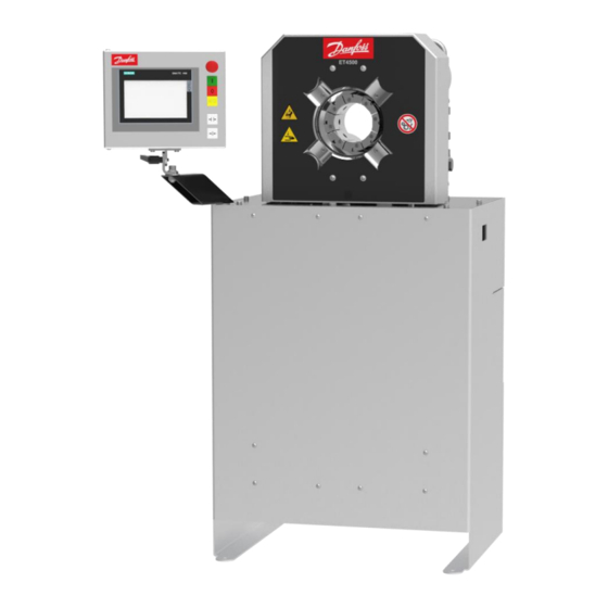
Machine description Design and function Basic machine (1) Crimping tool (2) Hydraulic tank (with electric motor, pump) (3) Main power switch (4) Control panel with buttons and control system CONTROL C.2 / (5) Emergency-stop button The crimping tool (1) is closed hydraulically, whereby the workpiece is formed. - Page 20 The position encoder system records the current position of the die system and transfers the value to the control system. Data records may be saved in the item memory and recalled at any time in the control system. Depending on the operation mode, the ac- tual forming process is controlled via the buttons on the control panel (4), the depth stop or the dual foot switch.
-
Page 21: Forming Process
Accessories The machine may be fitted with accessories. A list of the available ac- cessories is included in the Annex, Section "Accessories". Forming process There are two types of forming process with different target parame- ters: • Forming to a defined diameter •... - Page 22 WARNING! Risk of injuries! In particular non-metal workpieces may by overstressed by the forming process so that this may result in a sudden failure. Chips or seriously accelerated workpiece parts impose a high risk po- tential for operators, individuals and objects, even outside the working area! •...
-
Page 23: Operation And Display Elements C.2
Operation and display elements C.2 (1) Emergency-stop button (2) Illuminated Motor on button (3) Motor off button (4) Illuminated foot switch (5) Illuminated Open tool button (6) Illuminated Close tool button (7) Locking lever / angle setting (8) control panel of CONTROL C.2 The illuminated buttons may be arranged the other way round, depending on the control version. -
Page 24: Electric Sockets
(1) LAN socket for connection with a network. Network connection options are set out in the description of the relevant optional packages. (2) 2 x USB sockets (for the use of memory media, callipers or bar- code scanners certified by UNIFLEX, only) Electric sockets (1) Main power switch (2) Socket for single foot switch... -
Page 25: Foot Pedal (Accessory)
Foot pedal (accessory) (1) Close machine pedal (2) Open machine pedal WARNING! Risk by fatiguing posture! A static posture may result in work-related musculosceletal disor- ders and reduce productivity. • Make sure that operators have sufficient periods of relief and recreation. -
Page 26: Depth Stop (Accessory)
Depth stop (accessory) (1) Clamp lever (2) Sleeve (3) Plunger (4) Stop pin (5) Spacer (6) Clamping yoke (7) Guidance (8) Connection cable with plunger switch (9) Sleeve Operation modes The control unit provides for the following operation modes for operat- ing the forming tool: •... - Page 27 – Activate the button for closing and forming. The button is used for opening. – Dual foot switch The right foot switch is used for closing and forming. The left foot switch is used for opening. – Depth stop The tool is closed automatically when the workpiece acti- vates the depth stop by pressure.
- Page 28 The operation of the control system is described in a separate Op- eration Manual. This description is supplied with the machine.
-
Page 29: Technical Data
Technical data Machine Dimensions L x W x H 745 x 600 x 1360 mm Weight approx. 490 kg Control CONTROL CONTROL C.2 Operation mode S6-70% Noise level 69 dB(A)* Protection class IP 40 Function Forming force 2800 kN / 280 t Max. - Page 30 Die type Electrical connection Voltage variant 230 V 50/60 Hz, 3 phases 380 - 420 V 50 Hz, 3 phases 380 - 480 V 60 Hz, 3 phases Power rating 4 kW Back-up fuse 230 V: 20 A delayed, 380 - 480 V: 16 A delayed, preferably thermal fuses, if circuit breakers are used these should be of the class C type.
- Page 31 Ambient conditions C – 35 Ambient temperature 45 % – 65 % Air humidity The * data are theoretical/computed values, or values measured on a prototype. Actual values may vary slightly, depending on the ma- chine. The use of special hydraulic oil with improved properties and addi- tives can prolong the service life of the machine and extends the oil change interval.
-
Page 32: Transport And Commissioning
Transport and commissioning Transport The goods should be transported in the original packaging. During transport, the goods must be secured safely within the packaging. All applicable laws and regulations relating to securing loads shall be ob- served during transport. The machine/unit may only be unloaded and transported by means of a forklift, a lift truck or a crane. -
Page 33: Intermediate Storage Of Machine/Unit
WARNING! Danger from falling loads! Risk of injury from falling loads. • Do not stand under suspended loads. WARNING! Danger from tilting machine/unit! The machine/unit may tilt if it is transported improperly. There is a risk of being injured. • Consider the machine/unit's centre of gravity (1). -
Page 34: Filling Hydraulic Oil
WARNING! Risk by tilting machine! If not bolted to the floor, the machine may tilt. There is a risk of being injured. • Fix the machine on the floor. Use suitable bolts to fix the machine legs on the floor. Place the machine in a way so that it is easily accessible for main- tenance work from all sides. - Page 35 CAUTION! Risk of injuries! Contact with hydraulic oil and other consumables imposes a risk of injuries for the skin, eyes, respiratory and intestinal tracts! Hy- draulic liquid spills impose danger of slipping and falling! • Observe supplier's protection and safety instructions (see data sheet).
-
Page 36: Electrical Connection
Mount grating (1). Do not operate the machine for a minimum of four hours so that the dirt particles in the system may settle. 4.3.2 Electrical connection ATTENTION! Risk of damage to machinery The voltage range described in this Section is only permissible for multi-voltage machines (MVA). - Page 37 Place the voltage selection plug on the correct slot in the control cabinet - Δ 230 V at the bottom connection (3), Υ 400 V at the top connection (2). Set the motor protection switch (1) as specified in the Technical data.
- Page 38 ATTENTION! Risk of damage to machinery! Extended operation of the motor with an incorrect rotational di- rection or operating the machine without oil will destroy the hyd- raulic pump. • Make sure that the hydraulic oil filling in the machine is suffi- cient before starting the machine.
-
Page 39: Bleeding The Hydraulic System
4.3.3 Bleeding the hydraulic system Switch on the machine. Operate the machine in the idle mode for two minutes in order to fill the pump with oil. Open and close the tool several times. Check oil level, add hydraulic oil if required. -
Page 40: Operation
Operation What you have to observe The operator has received the Operation Manual from the owner, has read and understood it and will observe it. Before starting and/or re-starting • Ensure sufficient illumination of the working area of the ma- chine/unit. -
Page 41: Forming The Workpiece
Forming the workpiece 5.3.1 Prerequisites Prerequisites for a correct forming process: • The die system and the workpiece match each other. • The proper jaw system is correctly mounted in the tool. • The forming dimension and the dies have been entered in the control system, please also refer to "Setting the forming dimen- sion"... - Page 42 WARNING! Risk of squeezing! When the die system closes, there is a risk of getting squeezed between the die and the workpiece. • Keep the feed opening for the workpiece as small as possi- ble. • Keep a minimum distance of 120 mm (A) to the die system. Press the button to activate the dual foot switch.
-
Page 43: Operation Mode Buttons Control Panel
5.3.3 Operation mode buttons control panel WARNING! Risk of squeezing! When the die system closes, there is a risk of getting squeezed between the die and the workpiece. • Keep the feed opening for the workpiece as small as possi- ble. -
Page 44: Remote Automatic Mode, Via Depth Stop
actual dimension and the specified dimension (see “Setting the forming dimension” in Section 5). Open the crimping tool only so much that the hose may be placed and/or removed easily. Excessive opening means risk of squee- zing and time loss. 5.3.4 Remote automatic mode, via depth stop WARNING! Risk of squeezing! - Page 45 Hold the workpiece with one hand during forming; the workpiece must continuously activate the depth stop during forming. Manual operation mode: Press the button to open the ma- chine when the forming process is completed. Semi-automatic operation mode: Wait until the hold time defi- ned in the control has expired;...
-
Page 46: Changing The Crimping Dies
Changing the crimping dies 5.4.1 Changing the crimping dies using a die wrench Positioning the crimping dies Close the crimping tool until the holes (5) are visible for using the locking bolt. Switch off the machine using the main switch and secure it against switching on unintentionally. - Page 47 Place the crimping dies into the mounting hole (4) using the retaining bolt (2). Remove the die wrench (3) to release the pressure on the lo- cking bolt - the crimping die is now fixed. Always use a complete set of equal crimping dies with the same identification and diameter.
-
Page 48: Replacing The Intermediate Dies
Replacing the intermediate dies Position the intermediate dies Close the crimping tool until the holes (5) are visible for using the locking bolt. Switch off the machine using the main switch and secure it against switching on unintentionally. WARNING! Risk of squeezing! When the die system closes, there is a risk of getting squeezed between the dies. - Page 49 Remove the die wrench (3) to release the pressure on the lo- cking bolt - the intermediate die is now fixed. Always mount a complete set of identical intermediate dies with the same label and diameter. Removing the intermediate dies Close the crimping tool until the holes (5) are visible for using the locking bolt.
- Page 50 ATTENTION! Risk of damage to machinery! If the profile 266/268/237 intermediate dies (1) are placed in the tool by means of crimping dies PB 239 and QDC 239, the base dies, the locking bolts in the base dies as well as the retaining bolts of the intermediate and criming dies will be destroyed.
-
Page 51: Changing The Crimping Dies With The Quick Die Change System (Only Profile 239)
5.5.1 Changing the crimping dies with the quick die change system (only profile 239) Select the change position for crimping dies in the control by ac- tivating the button [QDC]. Press the button to open the crimping tool so that the dies type PB239 can just be inserted. - Page 52 ATTENTION! Risk of damage to machinery! The retaining bolts and the crimping dies will be destroyed if the retaining bolts do not fit in the mounting hole of the base dies or intermediate dies. • Pay attention to the correct position of the quick die change system with crimping dies.
-
Page 53: Depth Stop (Accessory)
ATTENTION! Risk of damage to machinery! If the crimping dies protrude beyond the basic and intermediate dies, the crimping dies, the intermediate dies and the machine will be damaged (see (X) in the figure). In the figure, the crimping die (2) is placed incorrectly. •... -
Page 54: Setting The Forming Dimension
(8) Connection cable with plunger switch (9) Sleeve Setting the forming dimension The forming dimension (X) must be set specifically for the workpiece. Read the forming dimension in the forming dimension table of the system supplier, e.g. Ø 17.4 mm. Select crimping dies with a smaller or the same diameter, e.g. -
Page 55: Stop
machines without any forming distance limitation, tools components may be damaged if the forming range is exceeded. Stop Complete the forming process. Deposit the work piece outside the machine. Deactivate the main switch (1). Check the machine for contamination, leaks and external da- mage. -
Page 56: Emergency Stop
5.10 Emergency stop In case of an emergency Immediately press the emergency-stop button (1) in cases of emergency. The crimping tool movement will be stopped. The drive unit is shut down. Restart after and emergency WARNING! Risk of injuries! The emergency-stop button was probably activated due to the occurrence of a hazardous situation. - Page 57 Vacuum the machine from metal abrasion (crimping scale) in the opened crimping tool, or use a soft cloth to clean it. For this pur- pose, remove the crimping dies and the intermediate dies.
-
Page 58: Maintenance
Maintenance Regular maintenance will ensure the continuous operation reliability of the device. What you have to observe This Section describes action to be taken by you as the fitter regularly to ensure the troublefree use of the machine/unit. • Maintenance work may only be performed by qualified mainte- nance staff (machine/unit fitters). - Page 59 Maintenance item Hydraulic system Hydraulic energy lines – hoses: Check for porosity and leaks. Hydraulic energy lines - bolted connections of hoses and pipes: Check for leaks. Hydraulic oil: Check oil level, add oil if required (see “Replacing hydraulic oil” in Section 6). Hydraulic oil: Replace Hydraulic hoses: Have replaced (DIN 20066) no later than six years after manufacture (see label).
-
Page 60: Hydraulic Oil Change
Hydraulic oil changes and wear part replacements must be recor- ded in the maintenance log! Hydraulic oil change CAUTION! Risk of injuries! Contact with hydraulic oil and other consumables imposes a risk of injuries for the skin, eyes, respiratory and intestinal tracts! Hyd- raulic liquid spills impose danger of slipping and falling! •... - Page 61 Deactivate the machine on the main switch and secure it against unintentional restart. Let the hydraulic oil cool down until the tank enclosure is warm to the touch. Dismantle the grating (1). Open the air ventilation cap (2). Pump out hydraulic oil using an external pump. Add new hydraulic oil (see “Technical Data”...
-
Page 62: Checking And Replacing Slide Bearing Plates
Checking and replacing slide bearing plates Checking slide bearing plates Check slide bearing plates for wear, replace defective parts. The slide bearing plate (1) is new, the slide bearing plate (2) is worn. ATTENTION! Risk of damage to machinery! Worn slide bearing plates may cause damage to the machine and lead to inaccuracies of the forming dimension. - Page 63 Replacing slide bearing plates Open the crimping tool fully. Deactivate the machine on the main switch and secure it against unintentional restart. Loosen bolts (1) on clamping ring (2). Remove clamping ring (2). Pull out old slide bearing plate (3). Insert the new slide bearing plate (3).
-
Page 65: Troubleshooting
Troubleshooting Error Cause Remedy Machine does not close/open Main switch is OFF Activate the main switch Voltage incorrect Check voltage supply Power plug defective Check power plug and replace if necessary Rotational direction of electric Check rotation direction, cor- motor incorrect rect electrical connection Insufficient amount of hydrau- Refill oil... -
Page 66: Decommissioning, Disposal
Decommissioning, disposal WARNING! Risk by electrical voltage! There is a risk of electrocution near the live parts! • Shut down the machine/unit. • Disconnect the machine/unit from the power supply. CAUTION! Risk of injuries! Contact with hydraulic oil and other consumables imposes a risk of injuries for the skin, eyes, respiratory and intestinal tracts! Hy- draulic liquid spills impose danger of slipping and falling! •... -
Page 67: Dismantling
CAUTION! Risk of injuries! Parts of the machine/unit may be under pressure and/or tension. Loosening components may impose a risk of injuries! • De-pressurize the machine/unit before performing any work and check for potential sources of hazard. Dismantling This section describes activities to be performed by you as the opera- tor to ensure the safe dismantling of the machine/unit. - Page 68 Return consumables, e.g. oils, greases, test media, to supplier - they are hazardous waste. Also observe the information given on the safety data sheet.
-
Page 69: Annex
Annex Individual machine/unit components may deviate in their features. Please indicate the serial number of the machine for spare part or- ders. -
Page 70: Accessories (Retrofittable)
Accessories (retrofittable) Accessories Part code Quick die change system QDC 239.5 Die deposit QDS 239 B QDS 239 C QDS 239 R TU-QDS crimping die deposit system TU-QDS F Basic TU-QDS F Shelf TU-QDS F 239 l End stop TA S6.2 manual TA S6.3 C A automatic C.2 Mirror SHS S6.2 Table machine... -
Page 71: Spare Parts List
Spare parts list 9.2.1 Tool Item Quantity Part code Designation 266.185.0 Pressure plate, front 266.187.4 Sleeve 266.191.0 Pressure plate, back 266.186.3 Ball nut 266.195.3 Bearing segment 1 set 266.5 Bearing plates 266.398.3 Hydraulic cylinder 266.215.3 Clamping segment 798.110128 Cylinder bolt DIN EN ISO 4762 – M8x100 798.120066 Cylinder bolt DIN EN ISO 4762 –... -
Page 72: Basic Dies
Item Quantity Part code Designation 798.750004 Snap ring DIN 127 Ø8 268.150 Pressure spring 266.193 Sleeve, Ø 45/Ø 50/ length long 1001 266.1192 Base dies mounted 266.1195 Complete tool 9.2.2 Basic dies Item Quantity Article code Designation 266.198.1 Basic dies 235.008.4 Locking pin 798.420027... -
Page 73: Mechanical Equipment
9.2.3 Mechanical equipment Item Quantity Part code Designation 268.280.1 + colour code Chassis 268.284.3 + colour code Grid 268.285.2 + colour code Cover plate 266.283.2 Mounting plate 266.224.2 + colour code Cover 777.924.2 Designation sign 266.256.3 Position encoder mounting angle 264.243.4 Position encoder stop bracket 266.255.3... - Page 74 Item Quantity Part code Designation No pic- 716.4 Warning of hand injuries sign ture...
-
Page 75: Hydraulic System
9.2.4 Hydraulic system Item Quantity Part code Designation 268.293.2 Tank cover 239.517 Suction filter 3/4” 239.518 Double pipe nipple... - Page 76 Item Quantity Part code Designation 239.520 Double pipe nipple 239.529 Angle 239.535 Angle 268.337 Hydraulic double pump 268.325.3 Hydraulic block, complete 777.349 NG 10 valve GN 552-R3/4"-A1 air ventilation caps 777.361 Gear pump flange 777.362 Gear pump flange 777.300 Bell housing 24/30N2a-28 Coupling 777.301.3...
-
Page 77: Electric Equipment
Item Quantity Part code Designation 220.916 Pressure sensor 0 - 400 bar 9.2.5 Electric equipment Item Quantity Part code Designation 807.601 E-plate, complete 888.652 Clamping block 888.653 Voltage selection plug 888.014 Motor protection switch 807.318 Switching power supply... - Page 78 Item Quantity Part code Designation 888.406 Interface module 888.411 Relay 888.410 Optical coupler 807.375 CPU Controller No pic- VME 0231 Fine wire fuse ture Item Quantity Part code Designation 807.710 Control panel 800 mm C.2 with memory card 807.374 Uniflex Touch Panel 777.022 Clamp lever 807.067...
-
Page 79: Spare Parts Kit
Item Quantity Part code Designation 800.202.3 Mounting plate 8.06.100 Main power switch 888.223 Mounted housing 888.224 Socket insert 888.227 Mounted housing 888.228 Socket insert, 3-pin 888.229 Socket insert, 4-pin 888.498 Cover plug Spare parts kit Quantity Part code Designation 1 set 266.5 Pressure plate slide bearing plate, back 1 set... -
Page 80: Service Tool
Quantity Part code Designation 8 per set 239.041.4 sw Plastic retaining pin (section: 239 / 239L) 8 per set 239.041.4 Retaining bolt, steel (profile: 239 / 239L) 8 per set 239.151 Pressure piece (profile: 239 / 239L) 8 per set 232.504.4 Retaining bolt (profile 266) 1 set... -
Page 81: Retaining Bolt For Standard Crimping Dies (Depending On Crimping Die)
Retaining bolt for standard crimping dies (depending on crimping die) Crimping die profile Retaining bolt 262.104.4 262.129.3 239.041.4 239.041.4 (sw) 232.504.4 Ø96 / Ø103 232.505.4 220.502.4... - Page 82 Crimping die profile Retaining bolt 245.114.4...
-
Page 83: Hydraulic Diagram
Hydraulic diagram... -
Page 84: Electric Diagram
Electric diagram... -
Page 92: Maintenance Log
Maintenance log Remark Date Signature ... -
Page 93: Declaration Of Qualified Staff
Declaration of qualified staff I herewith declare that I have attended an internal training for the operation of the UNIFLEX machine and have been informed on all safety-related details. In addition I declare that I have read and under- stood this Operation Manual completely. City Date Name...
Need help?
Do you have a question about the ET4500-002 and is the answer not in the manual?
Questions and answers