Table of Contents
Advertisement
Quick Links
Advertisement
Table of Contents

Subscribe to Our Youtube Channel
Related Manuals for Danfoss ET4500-001


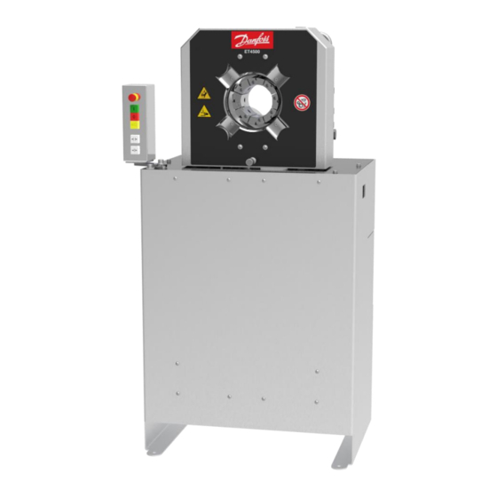
Summary of Contents for Danfoss ET4500-001
- Page 2 Imprint Manufacturer: UNIFLEX-Hydraulik GmbH Robert-Bosch-Strasse 50-52 D-61184 Karben Germany Phone: +49 (0) 60 39 / 91 71 - 0 Fax: +49 (0) 60 39 / 91 71 - 181 This Operating Manual of the machine is a translation; the origi- nal is in German.
- Page 4 In accordance with EC Machinery Directive 2006/42/EC and UK-Sup- ply of Machinery (Safety) Regulations 2008. The following machine Danfoss ET4500-001 was developed, designed and manufactured in compliance with EC Directive 2006/42/EC and UK-Supply of Machinery (Safety) Regulations 2008, in the sole responsibility of...
-
Page 5: Table Of Contents
Contents About this document ..................8 1.1 Target groups ....................8 1.2 Storage ....................... 10 1.3 Name plate ....................10 1.4 Voltage codes ..................... 10 Safety instructions .................... 11 2.1 Presentation of warnings ................11 2.2 Intended use ....................11 2.3 Product-specific risks .................. - Page 6 4.3.3 Bleeding the hydraulic system ............33 Operation ......................34 5.1 What you have to observe ................34 5.2 Start ......................34 5.3 Forming the workpiece ................35 5.3.1 Prerequisites ..................35 5.3.2 Operation mode buttons control panel ..........35 5.4 Changing the crimping dies .................
- Page 7 9.2.5 Electric equipment ................70 9.2.6 Control A ..................71 9.3 Spare parts kit ..................... 72 9.4 Service tool ....................72 9.5 Retaining bolt for standard crimping dies (depending on crimping die)..73 9.6 Hydraulic diagram ..................75 9.7 Electric diagram ..................76 9.8 Maintenance log..................
-
Page 8: About This Document
About this document In this Operation Manual, the “forming machine Danfoss ET4500- 001” is consistently referred to as machine. This Operation Manual includes important notes on how you operate your machine/unit safely, properly and economically. Use not in compliance with the intended purpose may result in hazard to the operator's health and life and/or in the risk of damage to/the machine/unit. - Page 9 • national provisions, occupational safety regulations and applica- ble environmental protection regulations are fully complied with; • persons working on the machine/unit are adequately qualified; • persons working on the machine/unit are suitable for operating the machine/unit; • the Operation Manual has been read and understood. One hard- copy of the Operation Manual must always be kept at a desig- nated place where the machine/unit is used.
-
Page 10: Storage
Storage The Operation Manual is part of the machine/unit and must be kept near the machine/unit at all times. Upon disposal of the machine/unit, the Operation Manual must also be handed over. Name plate The name plate is fixed near the power cable. Voltage codes Voltage variant Voltage rating... -
Page 11: Safety Instructions
Safety instructions Presentation of warnings Warning notes in the Operation Manual warn against risks involved with the handling of the machine/unit. Risk levels are identified as fol- lows: The signal word HAZARD identifies an imminent hazard resulting in HAZARD! serious injuries or death. This warning is supplemented by a triangu- lar hazard symbol. - Page 12 • use of eight identical original UNIFLEX dies with the same label or seven dies and one associated marking crimping die. • The machine must not be operated by persons not capable of operating the machine without any risk. These may include: ➢...
-
Page 13: Product-Specific Risks
Product-specific risks The machine/unit is designed in accordance with the latest state of technology. Nevertheless, the machine/unit may impose risks: 2.3.1 Risks imposed by mechanical equipment Risk of squeezing When the die system closes, there is a risk of getting squeezed between the die and the workpiece. -
Page 14: Risks Imposed By Noise
• Regularly check lines and bolted connections for leaks and visi- ble damage. Immediately remedy any damage detected. Repair work on the hydraulic system of the machine/unit or on its components may only be performed by UNIFLEX specialist staff. 2.3.4 Risks imposed by noise The noise level meter acc. -
Page 15: Risks In Case Of Fire
2.3.7 Risks in case of fire The operating staff has to be familiar with the location as well as with operating the fire alarm and fighting means. Free access to this equipment must be ensured. Never use water to extinguish a fire. For appropriate fire extinguishing action, please read the safety data sheet of the hydraulic oil supplier. -
Page 16: Emergency-Stop Button
• Keep access to hydraulic supply free 2.4.2 Emergency-stop button The emergency-stop button for the machine is located on the control panel. Immediately activate the emergency-stop button (1) in cases of emergency. Remedy the cause of the emergency stop first before unlocking the emergency-stop button. -
Page 17: Warning Signs On The Machine
The owner has to consider the need for adapted protection equip- ment before commissioning. If such need exists, the relevant protec- tion equipment has to be mounted before commissioning of the ma- chine. UNIFLEX will provide you with customized solutions for protection equipment upon request. - Page 18 Oiling / greasing prohibited on the die system Illegible or missing warning signs must immediately be replaced by the owner.
-
Page 19: Machine Description
Machine description Design and function Basic machine (1) Crimping tool (2) Micrometer (3) Hydraulic tank (with electric motor, pump) (4) Main power switch (5) Control panel with buttons (6) Emergency-stop button... - Page 20 The crimping tool (1) is closed hydraulically, whereby the workpiece is formed. The pressure needed for this purpose is built up by the electrically driven pump (2) in the cylinders. The actual forming process is controlled via the buttons on the control panel (5).
-
Page 21: Forming Process
Accessories The machine may be fitted with accessories. A list of the available ac- cessories is included in the Annex, Section "Accessories". Forming process There is one type of forming: • Forming to a defined diameter Forming to a defined diameter This is the standard process for forming to produce hydraulic hoses. -
Page 22: Operation And Display Elements
Operation and display elements (1) Emergency-stop button (2) Illuminated Motor On button Motor Off button (4) Illuminated foot switch button (5) Illuminated Open tool button (6) Illuminated Close tool button... -
Page 23: Depth Stop (Accessory)
Depth stop (accessory) (1) Clamp lever (2) Sleeve (3) Plunger (4) Stop pin (5) Spacer (6) Clamping yoke (7) Guidance (8) Sleeve... -
Page 24: Technical Data
Technical data Machine Dimensions L x W x H 750 x 600 x 1360 mm Weight approx. 360 kg Control CONTROL A Operation mode S6-70 % Noise level 70 dB(A)* Protection class IP 40 Function Forming force 2800 kN / 280 t Max. - Page 25 Workpiece capacity SAE R15/4SH 1 Part Fitting 2", depending on the fitting SAE R15 2 Part Fitting 1 1/2", depending on the fitting 4 SH 2 Part Fitting 2", depending on the fitting Industry 3" 90˚ bend 2", depending on the fitting Die type Electric connection Connection power...
- Page 26 Ambient conditions C – 35 Ambient temperature 45 % – 65 % Air humidity The *data are theoretical/computed values, or values measured on a prototype. Actual values may vary slightly, depending on the ma- chine.
-
Page 27: Transport And Commissioning
Transport and commissioning Transport The goods should be transported in the original packaging. During transport, the goods must be secured safely within the packaging. All applicable laws and regulations relating to securing loads shall be ob- served during transport. The machine/unit may only be unloaded and transported by means of a forklift, a lift truck or a crane. -
Page 28: Intermediate Storage Of Machine/Unit
WARNING! Danger from falling loads! Risk of injury from falling loads. • Do not stand under suspended loads. WARNING! Danger from tilting machine/unit! The machine/unit may tilt if it is transported improperly. There is a risk of being injured. • Consider the machine/unit's centre of gravity (1). -
Page 29: Filling Hydraulic Oil
WARNING! Risk by tilting machine! If not bolted to the floor, the machine may tilt. There is a risk of being injured. • Fix the machine on the floor. Use suitable bolts to fix the machine legs on the floor. Place the machine in a way so that it is easily accessible for main- tenance work from all sides. - Page 30 CAUTION! Risk of injuries! Contact with hydraulic oil and other consumables imposes a risk of injuries for the skin, eyes, respiratory and intestinal tracts! Hy- draulic liquid spills impose danger of slipping and falling! • Observe supplier's protection and safety instructions (see data sheet).
-
Page 31: Electrical Connection
Mount grating (1). Do not operate the machine for a minimum of four hours so that the dirt particles in the system may settle. 4.3.2 Electrical connection WARNING! Danger from electrical voltage! There is a risk of electrocution near the live parts! •... - Page 32 ATTENTION! Risk of damage to machinery! Prolonged operation of the motor with an incorrect rotational di- rection or operating the machine without oil will destroy the hyd- raulic pump. • Make sure that the amount of hydraulic oil in the machine is sufficient before starting the machine.
-
Page 33: Bleeding The Hydraulic System
4.3.3 Bleeding the hydraulic system Switch on the machine. Operate the machine in the idle mode for two minutes in order to fill the pump with oil. Open and close the tool several times. Check oil level, add hydraulic oil if required. -
Page 34: Operation
Operation What you have to observe The operator has received the Operation Manual from the owner, has read and understood it and will observe it. Before starting and/or re-starting • Ensure sufficient illumination of the working area of the ma- chine/unit. -
Page 35: Forming The Workpiece
Forming the workpiece 5.3.1 Prerequisites Prerequisites for a correct forming process: • The die system and the workpiece are compatible. • The proper jaw system is correctly mounted in the tool. • The forming dimension is set correctly, please also refer to “Set- ting the forming dimension”, Section 5. - Page 36 WARNING! Risk of squeezing! When the die system closes, there is a risk of getting squeezed between the die and the workpiece. • Keep the feed opening for the workpiece as small as possi- ble. • Keep a minimum distance of 120 mm (A) to the die system. Manually position the pre-mounted workpiece in the tool.
-
Page 37: Changing The Crimping Dies
Changing the crimping dies 5.4.1 Changing the crimping dies using a die wrench Positioning the crimping dies Close the crimping tool until the holes (5) are visible for using the locking bolt. Switch off the machine using the main switch and secure it against switching on unintentionally. - Page 38 Place the crimping dies into the mounting hole (4) using the retaining bolt (2). Remove the die wrench (3) to release the pressure on the lo- cking bolt - the crimping die is now fixed. Always use a complete set of equal crimping dies with the same identification and diameter.
-
Page 39: Replacing The Intermediate Dies
Replacing the intermediate dies Position the intermediate dies Close the crimping tool until the holes (5) are visible for using the locking bolt. Switch off the machine using the main switch and secure it against switching on unintentionally. WARNING! Risk of squeezing! When the die system closes, there is a risk of getting squeezed between the dies. - Page 40 Remove the die wrench (3) to release the pressure on the lo- cking bolt - the intermediate die is now fixed. Always mount a complete set of identical intermediate dies with the same label and diameter. Removing the intermediate dies Close the crimping tool until the holes (5) are visible for using the locking bolt.
- Page 41 ATTENTION! Risk of damage to machinery! If the profile 266/268/237 intermediate dies (1) are placed in the tool by means of crimping dies PB 239 and QDC 239, the base dies, the locking bolts in the base dies as well as the retaining bolts of the intermediate and criming dies will be destroyed.
-
Page 42: Changing The Crimping Dies With The Quick Die Change System (Only Profile 239)
5.5.1 Changing the crimping dies with the quick die change system (only profile 239) Set micrometer to 0.0 mm position. Open the crimping tool fully by activating the button. Push the eight pins of the quick die change system (1) into the front holes of the crimping dies (2). - Page 43 ATTENTION! Risk of damage to machinery! The retaining bolts and the crimping dies will be destroyed if the retaining bolts do not fit in the mounting hole of the base dies or intermediate dies. • Pay attention to the correct position of the quick die change system with crimping dies.
-
Page 44: Adjusting The Depth Stop
ATTENTION! Risk of damage to machinery! If the crimping dies protrude beyond the base and intermediate dies during forming, the crimping dies, the intermediate dies and the machine will be damaged (see (X) in the figure). In the figure, the crimping die (2) is placed incorrectly. •... - Page 45 Remove screw (6) and replace it with spacers (1). Assembly the clamping yoke (2) with the end stop on the spa- cers (1). WARNING! Risk of squeezing! There is risk of getting squeezed between the depth stop and the machine chassis when positioning the depth stop. •...
-
Page 46: Setting The Forming Dimension
Insert the fitting in the correct position. Position the fitting within the crimping surfaces and at least 2-4 mm away from the end of the crimping die. Press the button to close the crimping tool until the crimping dies are tight to the crimped sleeve. Disconnect machine from power supply and secure it against switching on unintentionally. -
Page 47: Forming Travel Limitation
Micrometer: Workpiece forming dimension less crimping die di- ameter Form the workpiece. Check the workpiece. If the dimension is reached: manufacture other identical workpie- ces. If the dimension is not reached: Adjust difference on control and/or in the micrometer, repeat the forming process and check the workpiece. -
Page 48: Emergency Stop
Inform the fitter in case of damage or other irregularities. 5.10 Emergency stop In case of an emergency Immediately press the emergency-stop button (1) in cases of emergency. The crimping tool movement will be stopped. The drive unit is shut down. Restart after and emergency WARNING! Risk of injuries! - Page 49 ATTENTION! Risk of damage to machinery! If the machine is cleaned with a steam jet or compressed air, dirt and water may ingress in the machine and cause serious da- mage. • Do not use a steam jet to clean the machine. •...
-
Page 50: Maintenance
Maintenance Regular maintenance will ensure the continuous operation reliability of the device. What you have to observe This Section describes action to be taken by you as the fitter regularly to ensure the troublefree use of the machine/unit. • Maintenance work may only be performed by qualified mainte- nance staff (machine/unit fitters). - Page 51 Maintenance item Hydraulic system Hydraulic energy lines – hoses: Check for porosity and leaks. Hydraulic energy lines - bolted connections of hoses and pipes: Check for leaks. Hydraulic oil: Check oil level, add oil if required (see “Replacing hydraulic oil” in Section 6). Hydraulic oil: Replace Hydraulic hoses: Have replaced (DIN 20066) no later than six years after manufacture (see label).
-
Page 52: Hydraulic Oil Change
Hydraulic oil changes and wear part replacements must be recor- ded in the maintenance log! Hydraulic oil change CAUTION! Risk of injuries! Contact with hydraulic oil and other consumables imposes a risk of injuries for the skin, eyes, respiratory and intestinal tracts! Hyd- raulic liquid spills impose danger of slipping and falling! •... - Page 53 Deactivate the machine on the main switch and secure it against unintentional restart. Let the hydraulic oil cool down until the tank enclosure is warm to the touch. Dismantle the grating (1). Open the air ventilation cap (2). Pump out hydraulic oil using an external pump. Add new hydraulic oil (see “Technical Data”...
-
Page 54: Checking And Replacing Slide Bearing Plates
Checking and replacing slide bearing plates Checking slide bearing plates Check slide bearing plates for wear, replace defective parts. The slide bearing plate (1) is new, the slide bearing plate (2) is worn. ATTENTION! Risk of damage to machinery! Worn slide bearing plates may cause damage to the machine and lead to inaccuracies of the forming dimension. - Page 55 Replacing slide bearing plates Open the crimping tool fully. Deactivate the machine on the main switch and secure it against unintentional restart. Loosen the hexagon socket head screws (1) on the clamping ring (2). Remove clamping ring (2). Pull out old slide bearing plate (3). Insert the new slide bearing plate (3).
-
Page 56: Micrometer Adjustment
Micrometer adjustment If the measured forming dimensions of the workpiece deviate from the forming dimensions of the crimping die when the micrometer is set to zero, the micrometer must be readjusted. Release the screws on the cover. Remove the cover (see “Annex” in Section 9). Loosen the counter-nut (1) of the contact screw (2). -
Page 57: Troubleshooting
Troubleshooting Error Cause Remedy Machine does not close/open Main switch is OFF Switch on the main switch Voltage incorrect Check voltage supply Power plug defective Check power plug and replace if necessary Rotational direction of electric Check rotation direction, cor- motor incorrect rect electrical connection Phase applied to neutral... -
Page 58: Decommissioning, Disposal
Decommissioning, disposal WARNING! Risk by electrical voltage! There is a risk of electrocution near the live parts! • Shut down the machine/unit. • Disconnect the machine/unit from the power supply. CAUTION! Risk of injuries! Contact with hydraulic oil and other consumables imposes a risk of injuries for the skin, eyes, respiratory and intestinal tracts! Hy- draulic liquid spills impose danger of slipping and falling! •... -
Page 59: Dismantling
CAUTION! Risk of injuries! Parts of the machine/unit may be under pressure and/or tension. Loosening components may impose a risk of injuries! • De-pressurize the machine/unit before performing any work and check for potential sources of hazard. Dismantling This section describes activities to be performed by you as the opera- tor to ensure the safe dismantling of the machine/unit. - Page 60 Return consumables, e.g. oils, greases, test media, to supplier - they are hazardous waste. Also observe the information given on the safety data sheet.
-
Page 61: Annex
Annex Individual machine/unit components may deviate in their features. Please indicate the serial number of the machine for spare part or- ders. -
Page 62: Accessories (Retrofittable)
Accessories (retrofittable) Accessories Part code Quick die change system QDC 239.5 Die deposit QDS 239 B QDS 239 C QDS 239 R TU-QDS crimping die deposit system TU-QDS F Basic TU-QDS F Shelf TU-QDS F 239 l End stop TA S6_S manual TA S6_S A automatic Mirror SHS S6.2 Table machine... -
Page 63: Spare Parts List
Spare parts list 9.2.1 Tool Item Quantity Part code Designation 266.185.0 Pressure plate, front 266.187.4 Sleeve 266.191.0 Pressure plate, back 266.186.3 Ball nut 266.195.3 Bearing segment 1 set 266.5 Bearing plates 266.398.3 Hydraulic cylinder 266.215.3 Clamping segment 798.110128 Cylinder bolt DIN EN ISO 4762 – M8x100 798.120066 Cylinder bolt DIN EN ISO 4762 –... -
Page 64: Basic Dies
Item Quantity Part code Designation 798.750004 Snap ring DIN 127 Ø8 268.150 Pressure spring 266.193 Sleeve, Ø 45/Ø 50/ length long 1001 266.1192 Base dies mounted 266.1195 Complete tool 9.2.2 Basic dies Item Quantity Article code Designation 266.198.1 Basic dies 235.008.4 Locking pin 798.420027... -
Page 65: Mechanical Equipment
9.2.3 Mechanical equipment Item Quantity Part code Designation 268.280.1 Chassis 268.284.3 Grid 268.283.2 Cover plate 266.281.2 Mounting plate 266.224.2 Cover 266.235.2 Designation sign Limit switch attachment 266.256.4 Mounting plate 211.502.3 Round closing blank UNIFLEX 266.282.4 Control holder 266.353 Level indicator... - Page 66 Item Quantity Part code Designation 268.280.1 Chassis 268.284.3 Grid 268.283.2 Cover plate 266.281.2 Mounting plate 266.224.2 Cover 268.349.2 Tank seal 715.4 Squeezing risk warning sign 578.4 Oil prohibition sign 716.4 Warning of hand injuries sign 219.400.3 Crimping micrometer...
-
Page 67: Hydraulic System
9.2.4 Hydraulic system Item Quantity Part code Designation 268.293.2 Tank cover 239.517 Suction filter 3/4” 239.518 Double pipe nipple... - Page 68 Item Quantity Part code Designation 239.520 Double pipe nipple 239.529 Angle 239.535 Angle 268.337 Hydraulic double pump 268.325.3 Hydraulic block, complete 777.349 NG 10 valve GN 552-R3/4"-A1 air ventilation caps 777.361 Gear pump flange 777.362 Gear pump flange 777.300 Bell housing 24/30N2a-28 Coupling 777.301.3...
- Page 69 Item Quantity Part code Designation 245.515 Piston pressure switch, pressure setting 40 bar...
-
Page 70: Electric Equipment
9.2.5 Electric equipment Item Quantity Part code Designation 266.4100 Metal sheet S6.x Control 805.A, complete 8.06.100 Main power switch 800.021 Safety isolating transformer 8.06.001 Motor protection switch 6.3 - 10 A 8.06.002 Motor protection switch 10 - 16 A No pic- 8.06.003 Auxiliary switch block ture... -
Page 71: Control A
Item Quantity Part code Designation 888.229 Socket insert 888.343 Coupling relay 322.400 Rectifier 9.2.6 Control A Item Quantity Part code Designation 805.A Control A, complete 888.628 Keyboard PCB 8.06.013 Emergency-stop button 800.061 “Motor Start” button 800.060 “Motor Stop” button 807.068 Button: Foot pedal switching 800.063 “Open”... -
Page 72: Spare Parts Kit
Item Quantity Part code Designation 800.062 “Close” button 888.615 Quick-action fitting 8.06.017 Emergency stop contact maker Spare parts kit Quantity Part code Designation 1 set 266.5 Pressure plate slide bearing plate, back 1 set 266.8 Bearing plate segments, front 8 per set 239.041.4 sw Plastic retaining pin (section: 239 / 239L) 8 per set... -
Page 73: Retaining Bolt For Standard Crimping Dies (Depending On Crimping Die)
Retaining bolt for standard crimping dies (depending on crimping die) Crimping die profile Retaining bolt 262.104.4 262.129.3 239.041.4 239.041.4 (sw) 232.504.4 Ø96 / Ø103 232.505.4 220.502.4... - Page 74 Crimping die profile Retaining bolt 245.114.4...
-
Page 75: Hydraulic Diagram
Hydraulic diagram... -
Page 76: Electric Diagram
Electric diagram... -
Page 79: Maintenance Log
Maintenance log Remark Date Signature ... -
Page 80: Declaration Of Qualified Staff
Declaration of qualified staff I herewith declare that I have attended an internal training for the operation of the UNIFLEX machine and have been informed on all safety-related details. In addition I declare that I have read and under- stood this Operation Manual completely. City Date Name...
Need help?
Do you have a question about the ET4500-001 and is the answer not in the manual?
Questions and answers