Table of Contents
Advertisement
Quick Links
Advertisement
Table of Contents

Subscribe to Our Youtube Channel
Related Manuals for Danfoss ET4250


Summary of Contents for Danfoss ET4250
- Page 2 Imprint Manufacturer: UNIFLEX-Hydraulik GmbH Robert-Bosch-Strasse 50-52 D-61184 Karben Germany Phone: +49 (0) 60 39 / 91 71 - 0 Fax: +49 (0) 60 39 / 91 71 - 181 This Operating Manual of the machine is a translation; the origi- nal is in German.
- Page 3 In accordance with EC Machinery Directive 2006/42/EC and UK-Sup- ply of Machinery (Safety) Regulations 2008. The following machine ET4250 was developed, designed and manufactured in compliance with EC Directive 2006/42/EC and UK-Supply of Machinery (Safety) Regulations 2008, in the sole responsibility of...
-
Page 4: Table Of Contents
Contents About this document ................... 7 1.1 Target groups ....................7 1.2 Storage ......................9 1.3 Name plate ....................9 1.4 Abbreviations ....................9 Safety instructions ..................... 10 2.1 Presentation of warnings ................10 2.2 Intended use ....................10 2.3 Product-specific risks ................... 11 2.3.1 Risks imposed by mechanical equipment ........ - Page 5 4.4 Bleeding the hydraulic system ..............30 Operation ......................34 5.1 What you have to observe ................34 5.2 Start ......................34 5.3 Forming the workpiece ................34 5.3.1 Prerequisites ..................34 5.3.2 Operation mode buttons control panel ..........35 5.4 Changing the crimping dies ................
- Page 6 9.5 Hydraulic diagram ..................64 9.6 Electric diagram ................... 64 9.7 Maintenance log ..................66 9.8 Declaration of qualified staff ................ 67...
-
Page 7: About This Document
About this document In this Operation Manual, the “forming machine ET4250” is consis- tently referred to as machine. This Operation Manual includes important notes on how you oper- ate your machine/unit safely, properly and economically. Use not in compliance with the intended purpose may result in haz- ard to the operator's health and life and/or in the risk of damage to/the machine/unit. - Page 8 • national provisions, occupational safety regulations and appli- cable environmental protection regulations are fully complied with; • persons working on the machine/unit are adequately qualified; • persons working on the machine/unit are suitable for operating the machine/unit; • the Operation Manual has been read and understood. One hardcopy of the Operation Manual must always be kept at a designated place where the machine/unit is used.
-
Page 9: Storage
Storage The Operation Manual is part of the machine/unit and must be kept near the machine/unit at all times. Upon disposal of the ma- chine/unit, the Operation Manual must also be handed over. Name plate The name plate is fixed near the power cable. Abbreviations Crimp Force Monitoring Manual Flow Divider... -
Page 10: Safety Instructions
Safety instructions Presentation of warnings Warning notes in the Operation Manual warn against risks involved with the handling of the machine/unit. Risk levels are identified as follows: The signal word HAZARD identifies an imminent hazard resulting in HAZARD! serious injuries or death. This warning is supplemented by a trian- gular hazard symbol. -
Page 11: Product-Specific Risks
• The machine must not be operated by persons not capable of operating the machine without any risk. These may include: ➢ persons with physical or mental disabilities; ➢ children and persons under age; ➢ persons with a restricted capability for the operation of machines (e.g. -
Page 12: Risks Imposed By Mechanical Equipment
2.3.1 Risks imposed by mechanical equipment Risk of squeezing When the die system closes, there is a risk of getting squeezed between the die and the workpiece. • Keep the feed opening for the workpiece as small as possible. • Keep sufficient distance to the die system. -
Page 13: Risks Imposed By Noise
2.3.4 Risks imposed by noise The noise level meter acc. to IEC 804, Class 2, was calibrated be- fore measuring. The operation of the machine/unit causes noise emissions of 70 dB(A) at the workplace. Noise protection is not required. Higher noise emissions may occur when other machine/unitry is simultaneously used at the workplace. -
Page 14: Safety
Safety 2.4.1 Working area The working area is defined as the area 1 metre all around the ma- chine (shaded). • Keep the working area free from trip hazards • Use ducts for lines and cables • Provide good illumination •... -
Page 15: Warning Signs On The Machine
The necessity of additional, workpiece-specific protection equip- ment may for instance arise for angled workpiece geometries need- ing a large opening for being inserted into the forming machine. The pressure joining of insulators, structural steel and steel ropes, too, may require special safeguards. The owner has to consider the need for adapted protection equip- ment before commissioning. - Page 16 Risk of squeezing on the die system Oiling / greasing prohibited on the die system Illegible or missing warning signs must immediately be replaced by the operator.
-
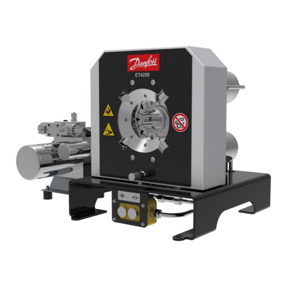
Page 17: Machine Description
Machine description Design and function Base machine (1) Crimping tool (2) Micrometer (3) Control console (4) Power unit (5) Manometer connection for pressure test (manometer measur- ing range: 0 – 400 bar) The crimping tool (1) is closed hydraulically, whereby the work piece is formed. - Page 18 Crimping tool The die system comprises base dies, intermediate dies (depending on the application) and crimping dies. All base dies are mounted on slide plates. The crimping dies and the intermediate dies, if present, are attached to the base dies (2). The intermediate dies are required if small work pieces are to be formed on a large machine.
-
Page 19: Operating Elements
Operating elements (1) Close tool button (2) Open tool button Depth stop (accessory) (1) Clamp (2) Clamp lever (3) Sleeve (4) Plunger (5) Pressure spring (6) Stop pin... -
Page 20: Forming Process
Forming process There is one type of forming: • Forming to a defined diameter Forming to a defined diameter This is the standard process for forming to produce hydraulic ho- ses. The crimping tool closes until it reaches a pre-set diameter, re- gardless of the required forming force. -
Page 21: Technical Data
S 3 L Technical data Machine Dimensions of machine 425 x 370 x 435 mm L x W x H Dimensions of power unit L x W 450 x 231 x 296 mm Machine weight approx. 110 kg Power unit weight approx. - Page 22 Work piece capacity " depending on the fitting SAE R12 / 4SP 1-part fittings ", depending on the fitting SAE R15 / 4SH 2-part fittings " depending on the fitting SAE R12 / 4SP 2-part fittings Industry 2" 90° bend ", depending on the fitting Die type Electrical connection...
- Page 23 Ambient conditions C – 35 Ambient temperature 45 % – 65 % Air humidity The * data are theoretical/computed values, or values measured on a prototype. Actual values may vary slightly, depending on the ma- chine.
-
Page 24: Transport And Commissioning
Transport and commissioning Transport The goods should be transported in the original packaging. During transport, the goods must be secured safely within the packaging. All applicable laws and regulations relating to securing loads shall be observed during transport. The machine must only be unloaded and transported with a crane. Lifting gear with a sufficient length, width and lifting capacity must be used. -
Page 25: Intermediate Storage Of Machine/Unit
WARNING! Danger from tilting machine! The machine may tilt if it is transported improperly. There is a risk of being injured. • Consider the machine's centre of gravity (1). • Lift the machine by the crimping tool. Thread the lifting belt with protective hose or fixed coating pur- suant to DIN EN 1492-1 with a width of 120 mm through the crimping tool. - Page 26 The workbench must be sufficiently solid and stable. Place the machine in a way so that it is easily accessible for main- tenance work from all sides. Check the machine for damage. Check the electric cables for damage. Train the operating staff and record training sessions in “Dec- laration of trained staff”, Section 9.
-
Page 27: Connecting The Hydraulic Unit
4.3.1 Connecting the hydraulic unit 4. Remove the protective caps on the hydraulic unit (1). 5. Remove the protective caps on the machine (2). 6. Connect the connections A, B and T with hose assemblies. 4.3.2 Filling hydraulic oil If the UNIFLEX forming machine was purchased without filled hyd- raulic oil, the suitable, new, clean and pre-filtered hydraulic oil has to be filled before commissioning (for oil type, please refer to "Technical data"... - Page 28 CAUTION! Risk of injuries! Contact with hydraulic oil and other consumables imposes a risk of injuries for the skin, eyes, respiratory and intestinal tracts! Hyd- raulic liquid spills impose a danger of slipping and falling! • Observe supplier's protection and safety instructions (see data sheet).
-
Page 29: Electrical Connection
4.3.3 Electrical connection WARNING! Risk by electrical voltage! There is a risk of electrocution near the live parts! • Work on electric systems may only be performed by qualified electricians or instructed and trained persons under the su- pervision of a qualified electrician. •... -
Page 30: Bleeding The Hydraulic System
Make sure that the power cable has been installed correctly and properly. Improper installation may result in excessive heating of the connection terminals and the power cable. A minimum of 88 Ah battery power of the vehicle is required. Do not use any gel batteries. - Page 31 CAUTION! Risk of injuries! Risk of injuries in case of contact of hydraulic oil with skin and eyes! • Observe supplier's protection and safety instructions (see data sheet). • Wear personal protection equipment. • Do not eat, drink or smoke when handling hydraulic oil. •...
- Page 32 The machine may only be pressurised slightly. Release pressure by activating the plungers A and/or B on the solenoid valve. WARNING! Risk of injuries! If the air ventilation cap is unscrewed excessively, it may be ejec- ted by the hydraulic system pressure and cause injuries, e.g. to the eyes.
- Page 33 10. Switch off the machine using the main switch and secure it against switching on unintentionally. 11. Mount the cover.
-
Page 34: Operation
Operation What you have to observe The operator has received the Operation Manual from the owner, has read and understood it and will observe it. Before starting and/or re-starting • Ensure sufficient illumination of the working area of the ma- chine/unit. -
Page 35: Operation Mode Buttons Control Panel
• Preferably form the workpiece in the centre of the crimping die length. Eccentric forming will result in a conical forming result and increased lopsided wear on the die system and the bea- ring plates. 5.3.2 Operation mode buttons control panel WARNING! Risk of squeezing! When the die system closes, there is a risk of getting squeezed... -
Page 36: Changing The Crimping Dies
the actual dimension and the specified dimension (see "Set- ting the forming dimension" in Section 5). WARNING! Risk of squeezing! When the die system closes, there is a risk of getting squeezed between the die and the workpiece. • Open the crimping tool only so much that the hose may be placed and/or removed easily. - Page 37 WARNING! Risk of squeezing! When the die system closes, there is a risk of getting squeezed between the dies. • Only replace the crimping dies when the machine is switched off. Use the supplied die wrench (4) to push and hold the locking bolt backward in the basic die (3).
-
Page 38: Changing The Crimping Dies With The Quick Die Change System (Only Profile 239)
After forming heavy fittings, the locking bolt may be slightly slug- gish. In this case, use a mallet to release the locking bolt by slightly hitting on the die wrench. 5.4.2 Changing the crimping dies with the quick die change system (only profile 239) Set micrometer to 0.0 mm position. - Page 39 WARNING! Risk of squeezing! When the die system closes, there is a risk of getting squeezed between the dies. • Take care that no parts of your body are inside the forming area when the crimping dies close. ATTENTION! Risk of damage to machinery! The retaining bolts and the crimping dies will be destroyed if the retaining bolts do not fit in the mounting hole of the base dies or intermediate dies.
-
Page 40: Adjusting The Depth Stop
ATTENTION! Risk of damage to machinery! If the crimping dies protrude beyond the base and intermediate dies during forming, the crimping dies, the intermediate dies and the machine will be damaged (see (X) in the figure). In the figure, the crimping die (2) is placed incorrectly. •... - Page 41 Mount the depth stop clamp (2) on the machine back using cy- linder bolts (3). WARNING! Risk of squeezing! There is risk of getting squeezed between the depth stop and the machine chassis when positioning the depth stop. • Do not touch the stop pin. •...
-
Page 42: Setting The Forming Dimension
Press the button to close the crimping tool until the crimp- ing dies are tight to the crimped sleeve. Disconnect machine from power supply and secure it against switching on unintentionally. Loosen the clamp lever (4). Push the sleeve with stop pin (1) towards the fitting. Tighten the clamping lever (4). -
Page 43: Forming Travel Limitation
Check the workpiece. If the dimension is reached: manufacture other identical work- pieces. If the dimension is not reached: Adjust difference on control and/or in the micrometer, repeat the forming process and check the workpiece. Forming travel limitation If the forming process is started outside the maximum forming range, see “Technical data”... -
Page 44: Emergency Stop
Emergency stop In case of an emergency Actuate the battery disconnection switch immediately in the event of an emergency. The crimping tool movement will be stopped. The drive unit is shut down. Restart after and emergency WARNING! Risk of injuries! The battery disconnection switch was probably activated due to the occurrence of a hazardous situation. -
Page 45: Maintenance
Maintenance Regular maintenance will ensure the continuous operation reliability of the device. What you have to observe This Section describes action to be taken by you as the fitter regu- larly to ensure the troublefree use of the machine/unit. • Maintenance work may only be performed by qualified mainte- nance staff (machine/unit fitters). - Page 46 Maintenance item Hydraulic system Hydraulic energy lines – hoses: Check for porosity and leaks. Hydraulic energy lines - bolted connections of hoses and pipes: Check for leaks. Hydraulic oil: Check oil level, add oil if required (see “Replacing hydraulic oil” in Section 6). Hydraulic oil: Replace Hydraulic hoses: Have replaced (DIN 20066) no later than six years after manufacture (see label).
-
Page 47: Hydraulic Oil Change
Hydraulic oil changes and wear part replacements must be recor- ded in the maintenance log! Hydraulic oil change CAUTION! Risk of injuries! Contact with hydraulic oil and other consumables imposes a risk of injuries for the skin, eyes, respiratory and intestinal tracts! Hyd- raulic liquid spills impose danger of slipping and falling! •... - Page 48 Disconnect machine from power supply and secure it against switching on unintentionally. Let the hydraulic oil cool down until the tank enclosure is warm to the touch. Open the air ventilation cap (1). Pump out hydraulic oil using an external pump. Add new hydraulic oil (see “Technical Data”...
-
Page 49: Checking And Replacing Slide Bearing Plates
Checking and replacing slide bearing plates Checking slide bearing plates Check slide bearing plates for wear, replace defective parts. The slide bearing plate (1) is new, the slide bearing plate (2) is worn. ATTENTION! Risk of damage to machinery! Worn slide bearing plates may cause damage to the machine and lead to inaccuracies of the forming dimension. - Page 50 Replacing slide bearing plates Open the crimping tool fully. Deactivate the machine on the main switch and secure it against unintentional restart. Loosen bolts (1) on clamping ring (2). Remove clamping ring (2). Pull out old slide bearing plate (3). Insert the new slide bearing plate (3).
-
Page 51: Micrometer Adjustment
Micrometer adjustment If the measured forming dimensions of the workpiece deviate from the forming dimensions of the crimping die when the micrometer is set to zero, the micrometer must be readjusted. Release the screws on the cover. Remove the cover (see “Annex” in Section 9). Loosen the counter-nut (1) of the contact screw (2). -
Page 52: Troubleshooting
Troubleshooting Error Cause Remedy Machine does not close/open Battery disconnection switch Actuate the battery disconnec- set to OFF tion switch Voltage incorrect Check voltage supply Insufficient amount of hydrau- Refill oil lic oil Power unit defective Check power unit Operation buttons defective Check operation buttons and replace, if required Machine forms unevenly/coni-... -
Page 53: Decommissioning, Disposal
Decommissioning, disposal WARNING! Risk by electrical voltage! There is a risk of electrocution near the live parts! • Shut down the machine/unit. • Disconnect the machine/unit from the power supply. CAUTION! Risk of injuries! Contact with hydraulic oil and other consumables imposes a risk of injuries for the skin, eyes, respiratory and intestinal tracts! Hy- draulic liquid spills impose danger of slipping and falling! •... -
Page 54: Dismantling
Dismantling This section describes activities to be performed by you as the op- erator to ensure the safe dismantling of the machine/unit. • The machine/unit may only be dismantled by entrusted and qualified staff. • Open the machine/unit completely. • Depressurise the machine/unit before dismantling it (deacti- vate the hydraulic pump and secure it against restart;... -
Page 55: Annex
Annex Individual machine/unit components may deviate in their features. Please indicate the serial number of the machine for spare part or- ders. -
Page 56: Accessories (Retrofittable)
Accessories (retrofittable) Accessories Part code Unit of delivery quan- tity Simple and quick die change system QDC 239.5 1 item Die deposit QDS 239 B 1 item QDS 239 C 1 item QDS 239 R 1 item TU-QDS crimping die deposit system TU-QDS F Basic 1 item TU-QDS F Shelf... -
Page 57: Spare Parts List
Spare parts list 9.2.1 Tool Item Quantity Part code Designation 264.191.0 Pressure plate, back 264.171.0 Pressure plate, front 263.390.3 Hydraulic cylinder 264.2 Base dies set 264.194.3 Ball nut 264.186.4 Sleeve 264.185.3 Bearing segment 264.196.4 Bearing plate, rear pressure plate 798.320003 T-groove nut... - Page 58 Item Quantity Part code Designation Cylinder screw with hexagon socket ISO 798.110088 4762 – M4x8 - galvanised 798.120068 Cylinder screw with hexagon socket DIN 4762 – M5x10 - 12.9 798.110103 Cylinder screw with hexagon socket ISO 4762 – M5x35 - galvanised Washer DIN EN ISO 7089 –...
-
Page 59: Mechanical Equipment
9.2.2 Mechanical equipment Item Quantity Part code Designation 8.12.041 Position switch 264.248.4 Mounting plate, roller switch... -
Page 60: Hydraulic Unit Dc
Item Quantity Part code Designation 245.515 Piston-type pressure switch 263.257.3 Protective plate, left side 263.241.3 Angle for switch 8.12.037 Mounted housing Z-15-GQ3 Limit switch 263.214.3 Tool holder 263.258.3 Protective plate, right side 263.255.3 Protective plate, top 263.241.3 Angle for switch 264.406 Switch 219.400.3... -
Page 61: Spare Parts Kit
Item Quantity Article code Designation 263.350 Hydraulic unit 12 V DC 263.354 Hydraulic unit 24 V DC 263.353 Way-valve 12 V DC 227.001 Way-valve 24 V DC DIN 125-1 - B 8.4 Washer DIN 934 - M8 Hexagon nut 300.001 Rubber buffer VKAM06S Sealing plug... -
Page 62: Retaining Bolt For Standard Crimping Dies (Depending On Crimping Die)
Retaining bolt for standard crimping dies (depending on crimping die) Crimping die profile Retaining bolt 262.104.4 262.129.3 239.041.4 239.041.4 (sw) 232.504.4 Ø96 / Ø103 232.505.4 220.502.4 245.114.4... -
Page 64: Hydraulic Diagram
Hydraulic diagram Electric diagram... -
Page 66: Maintenance Log
Maintenance log Remark Date Signature ... -
Page 67: Declaration Of Qualified Staff
Declaration of qualified staff I herewith declare that I have attended an internal training for the operation of the UNIFLEX machine and have been informed on all safety-related details. In addition I declare that I have read and un- derstood this Operation Manual completely. City Date Name...
Need help?
Do you have a question about the ET4250 and is the answer not in the manual?
Questions and answers