Table of Contents
Advertisement
Quick Links
Advertisement
Table of Contents

Related Manuals for Danfoss ET4300


Summary of Contents for Danfoss ET4300
- Page 2 Imprint Manufacturer: UNIFLEX-Hydraulik GmbH Robert-Bosch-Strasse 50-52 D-61184 Karben Germany Phone: +49 (0) 60 39 / 91 71 - 0 Fax: +49 (0) 60 39 / 91 71 - 181 This Operating Manual of the machine is a translation; the origi- nal is in German.
- Page 4 In accordance with EC Machinery Directive 2006/42/EC and UK-Sup- ply of Machinery (Safety) Regulations 2008. The following machine Danfoss ET4300 was developed, designed and manufactured in compliance with EC Directive 2006/42/EC and UK-Supply of Machinery (Safety) Regulations 2008, in the sole responsibility of...
-
Page 5: Table Of Contents
Contents About this document ..................8 1.1 Target groups ....................8 1.2 Storage ....................... 10 1.3 Name plate ....................10 1.4 Abbreviations ....................10 1.5 Voltage codes ..................... 10 Safety instructions .................... 11 2.1 Presentation of warnings ................11 2.2 Intended use ....................11 2.3 Product-specific risks .................. - Page 6 4.3.1 Filling hydraulic oil ................30 4.3.2 Electrical connection ................ 32 4.3.3 Bleeding the hydraulic system ............33 Operation ......................34 5.1 What you have to observe ................34 5.2 Start ......................34 5.3 Forming the workpiece ................35 5.3.1 Prerequisites ..................35 5.3.2 Operation mode buttons control panel ..........
- Page 7 9.4 Spare parts kit ..................... 63 9.5 Service tool ....................64 9.6 Retaining bolt for standard crimping dies (depending on crimping die)..65 9.7 Hydraulic diagram ..................67 9.8 Electric diagram ..................68 9.9 Maintenance log..................70 9.10 Declaration of qualified staff ................ 71...
-
Page 8: About This Document
About this document In this Operation Manual, the “forming machine Danfoss ET4300” is consistently referred to as machine. This Operation Manual includes important notes on how you operate your machine/unit safely, properly and economically. Use not in compliance with the intended purpose may result in hazard to the operator's health and life and/or in the risk of damage to/the machine/unit. - Page 9 • national provisions, occupational safety regulations and applica- ble environmental protection regulations are fully complied with; • persons working on the machine/unit are adequately qualified; • persons working on the machine/unit are suitable for operating the machine/unit; • the Operation Manual has been read and understood. One hard- copy of the Operation Manual must always be kept at a desig- nated place where the machine/unit is used.
-
Page 10: Storage
Storage The Operation Manual is part of the machine/unit and must be kept near the machine/unit at all times. Upon disposal of the machine/unit, the Operation Manual must also be handed over. Name plate The name plate is fixed near the power cable. Abbreviations Crimp Force Monitoring Manual Flow Divider... -
Page 11: Safety Instructions
Safety instructions Presentation of warnings Warning notes in the Operation Manual warn against risks involved with the handling of the machine/unit. Risk levels are identified as fol- lows: The signal word HAZARD identifies an imminent hazard resulting in HAZARD! serious injuries or death. This warning is supplemented by a triangu- lar hazard symbol. - Page 12 • use of eight identical original UNIFLEX dies with the same label or seven dies and one associated marking crimping die. • The machine must not be operated by persons not capable of operating the machine without any risk. These may include: ➢...
-
Page 13: Product-Specific Risks
Product-specific risks The machine/unit is designed in accordance with the latest state of technology. Nevertheless, the machine/unit may impose risks: 2.3.1 Risks imposed by mechanical equipment Risk of squeezing When the die system closes, there is a risk of getting squeezed between the die and the workpiece. -
Page 14: Risks Imposed By Noise
• Regularly check lines and bolted connections for leaks and visi- ble damage. Immediately remedy any damage detected. Repair work on the hydraulic system of the machine/unit or on its components may only be performed by UNIFLEX specialist staff. 2.3.4 Risks imposed by noise The noise level meter acc. -
Page 15: Safety
Never use water to extinguish a fire. For appropriate fire extinguishing action, please read the safety data sheet of the hydraulic oil supplier. Safety 2.4.1 Working area The working area is defined as the area 1 metre all around the ma- chine (shaded). -
Page 16: Emergency-Stop
2.4.2 Emergency-Stop The machine is fitted with an emergency-stop switch on the control panel. Immediately activate the emergency-stop switch (1) in cases of emergency. Remedy the cause of the emergency stop first before re-starting the machine. 2.4.3 Protection equipment Due to the variety of customer-specific workpieces, UNIFLEX is not capable of supplying additional standard protection equipment to- gether with the machine for the prevention of potential residual risks imposed by the machine. -
Page 17: Warning Signs On The Machine
The owner has to consider the need for adapted protection equip- ment before commissioning. If such need exists, the relevant protec- tion equipment has to be mounted before commissioning of the ma- chine. UNIFLEX will provide you with customized solutions for protection equipment upon request. - Page 18 Oiling / greasing prohibited on the die system Illegible or missing warning signs must immediately be replaced by the operator.
-
Page 19: Machine Description
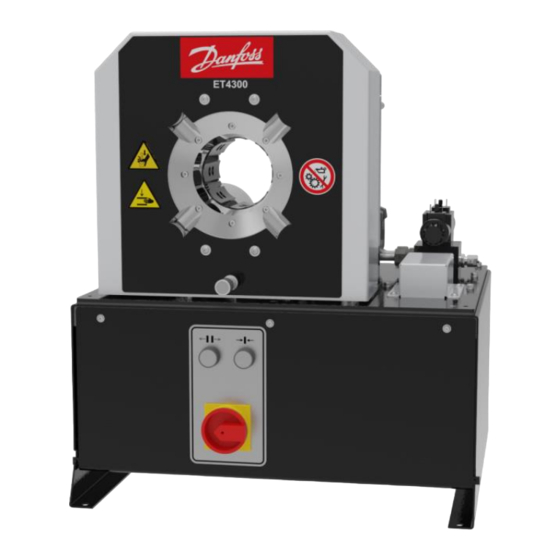
Machine description Design and function Base machine (1) Manometer connection for pressure test (manometer measuring range: 0 – 400 bar) (2) Hydraulic tank (with electric motor, pump) (3) Main switch/ Emergency-stop button (4) Control console (5) Micrometer (6) Crimping tool The crimping tool (6) is closed hydraulically, whereby the work piece is formed. -
Page 20: Accessories
Crimping tool The die system comprises base dies, intermediate dies (depending on the application) and crimping dies. All base dies are mounted on slide plates. The crimping dies and the intermediate dies, if present, are attached to the base dies (2). The intermediate dies are required if small work pieces are to be formed on a large machine. -
Page 21: Forming Process
Forming process There is one type of forming: • Forming to a defined diameter Forming to a defined diameter This is the standard process for forming to produce hydraulic hoses. The crimping tool closes until it reaches a pre-set diameter, regar- dless of the required forming force. -
Page 22: Operation And Display Elements
Operation and display elements (1) Close tool button (2) Main switch / emergency-stop button (3) Open tool button Depth stop (accessory) (1) Connection cable with plunger switch... - Page 23 (2) Clamp lever (3) Compression spring (4) Compression spring (5) Stop cone (6) Clamp (7) Bushing (8) Plunger + sleeve...
-
Page 24: Technical Data
Technical data Machine Dimensions L x W x H 592 x 545 x 672 mm Weight approx. 160 kg Control CONTROL A Operation mode S3-30% Noise level < 70 dB(A)* Protection class IP 40 Function Forming force 1800 kN / 180 t Max. - Page 25 Electrical connection See “Voltage code” in Section 1 Voltage rating Power rating 2,2 kW Back-up fuse 25 A delayed, preferably thermal fuses, if circuit breakers are used these should be of the class C type. Short circuit current lk3p 6,7 kA Short circuit current lp3p 9,7 kA Full load current of circuit...
- Page 26 We recommend industrial flooring which meets the following structural requirements Permanent floor loading Approx. 0.07 kg/mm Floor carrying capacity Min. 2500 kg/m Floor quality Evenness Max. unevenness 5 mm/m Inclination max. 5 mm/m Ambient conditions C – 35 Ambient temperature 45 % –...
-
Page 27: Transport And Commissioning
Transport and commissioning Transport The goods should be transported in the original packaging. During transport, the goods must be secured safely within the packaging. All applicable laws and regulations relating to securing loads shall be ob- served during transport. The machine must only be unloaded and transported with a crane. Lifting gear with a sufficient length, width and lifting capacity must be used. - Page 28 WARNING! Danger from falling loads! Risk of injury from falling loads. • Do not stand under suspended loads. WARNING! Danger from tilting machine! The machine may tilt if it is transported improperly. There is a risk of being injured. • Consider the machine's centre of gravity (1).
-
Page 29: Intermediate Storage Of Machine/Unit
Intermediate storage of machine/unit If the machine/unit cannot be mounted immediately upon delivery, it must be protected against: • Contamination, • Weather influences, • Mechanical damage. The machine/unit components may only be stored in closed rooms and under the following conditions: •... -
Page 30: Filling Hydraulic Oil
WARNING! Risk of injuries! Machine components might loosen during transport. Such com- ponents might be flung out during to the forming process. There is a risk of being injured. • Open and close the machine several times without any work- piece. - Page 31 CAUTION! Risk of injuries! Contact with hydraulic oil and other consumables imposes a risk of injuries for the skin, eyes, respiratory and intestinal tracts! Hy- draulic liquid spills impose a danger of slipping and falling! • Observe supplier's protection and safety instructions (see data sheet).
-
Page 32: Electrical Connection
2. Add hydraulic oil; for quantity and type, please refer to "Technical data" in Section 3. The oil level can be read on the dipstick of the air ventilation cap. The oil level should be at the centre of the marking. -
Page 33: Bleeding The Hydraulic System
ATTENTION! Risk of damage to machinery! Prolonged operation of the motor with an incorrect rotational di- rection or operating the machine without oil will destroy the hyd- raulic pump. • Make sure that the amount of hydraulic oil in the machine is sufficient before starting the machine. -
Page 34: Operation
Operation What you have to observe The operator has received the Operation Manual from the owner, has read and understood it and will observe it. Before starting and/or re-starting • Ensure sufficient illumination of the working area of the ma- chine/unit. -
Page 35: Forming The Workpiece
Forming the workpiece 5.3.1 Prerequisites Prerequisites for a correct forming process: • The die system and the workpiece are compatible. • The proper jaw system is correctly mounted in the tool. • The forming dimension is set correctly, please also refer to “Set- ting the forming dimension”, Section 5. - Page 36 WARNING! Risk of squeezing! When the die system closes, there is a risk of getting squeezed between the die and the workpiece. • Keep the feed opening for the workpiece as small as possi- ble. • Keep a minimum distance of 120 mm (A) to the die system. Manually position the pre-mounted workpiece in the tool.
-
Page 37: Changing The Crimping Dies With The Quick Die Change System (Only Profile 239)
5.3.3 Changing the crimping dies with the quick die change system (only profile 239) Set micrometer to 0.0 mm position. Open the crimping tool fully by activating the button. Push the eight pins of the quick die change system (1) into the front holes of the crimping dies (2). - Page 38 ATTENTION! Risk of damage to machinery! The retaining bolts and the crimping dies will be destroyed if the retaining bolts do not fit in the mounting hole of the base dies or intermediate dies. • Pay attention to the correct position of the quick die change system with crimping dies.
-
Page 39: Adjusting The Depth Stop
ATTENTION! Risk of damage to machinery! If the crimping dies protrude beyond the base and intermediate dies during forming, the crimping dies, the intermediate dies and the machine will be damaged (see (X) in the figure). In the figure, the crimping die (2) is placed incorrectly. •... - Page 40 Replace the screws (1) by the cylinder bolt, the washer and the circlip. Connect the cable (3) into the socket for the depth stop. WARNING! Risk of squeezing! There is risk of getting squeezed between the depth stop and the machine chassis when positioning the depth stop.
- Page 41 Insert the fitting in the correct position. Position the fitting within the crimping surfaces and at least 2 - 4 mm away from the end of the crimping die. Press the button to close the crimping tool until the crimping dies are tight to the crimped sleeve.
-
Page 42: Setting The Forming Dimension
Setting the forming dimension The forming dimension (X) must be set specifically for the workpiece. Read the forming dimension in the forming dimension table of the system supplier, e.g. Ø 17.4 mm. Select crimping dies with a smaller or the same diameter, e.g. Ø... -
Page 43: Stop
Stop Complete the forming process. Deposit the work piece outside the machine. Deactivate the main switch (1). Check the machine for contamination, leaks and external da- mage. Check the crimping tool and retaining bolts for contamination, damage and secure fitting. Check the oil level. -
Page 44: Emergency Stop
Emergency stop In case of an emergency Immediately deactivate the emergency-stop switch in cases of emergency. The crimping tool movement will be stopped. The drive unit is shut down. Restart after and emergency WARNING! Risk of injuries! The emergency-stop button was probably activated due to the occurrence of a hazardous situation. - Page 45 Vacuum the machine from metal abrasion (crimping scale) in the opened crimping tool, or use a soft cloth to clean it. For this pur- pose, remove the crimping dies and the intermediate dies.
-
Page 46: Maintenance
Maintenance Regular maintenance will ensure the continuous operation reliability of the device. What you have to observe This Section describes action to be taken by you as the fitter regularly to ensure the troublefree use of the machine/unit. • Maintenance work may only be performed by qualified mainte- nance staff (machine/unit fitters). - Page 47 Maintenance item Hydraulic system Hydraulic energy lines – hoses: Check for porosity and leaks. Hydraulic energy lines - bolted connections of hoses and pipes: Check for leaks. Hydraulic oil: Check oil level, add oil if required (see “Replacing hydraulic oil” in Section 6). Hydraulic oil: Replace Hydraulic hoses: Have replaced (DIN 20066) no later than six years after manufacture (see label).
-
Page 48: Hydraulic Oil Change
Hydraulic oil changes and wear part replacements must be recor- ded in the maintenance log! Hydraulic oil change CAUTION! Risk of injuries! Contact with hydraulic oil and other consumables imposes a risk of injuries for the skin, eyes, respiratory and intestinal tracts! Hyd- raulic liquid spills impose danger of slipping and falling! •... - Page 49 Disconnect machine from power supply and secure it against switching on unintentionally. Let the hydraulic oil cool down until the tank enclosure is warm to the touch. Open the air ventilation cap (1). Pump out hydraulic oil using an external pump. Add new hydraulic oil (see “Technical Data”...
-
Page 50: Checking And Replacing Slide Bearing Plates
Checking and replacing slide bearing plates Checking slide bearing plates Check slide bearing plates for wear, replace defective parts. The slide bearing plate (1) is new, the slide bearing plate (2) is worn. ATTENTION! Risk of damage to machinery! Worn slide bearing plates may cause damage to the machine and lead to inaccuracies of the forming dimension. - Page 51 Replacing slide bearing plates Open the crimping tool fully. Deactivate the machine on the main switch and secure it against unintentional restart. Loosen the hexagon socket head screws (1) on the clamping ring (2). Remove clamping ring (2). Pull out old slide bearing plate (3). Insert the new slide bearing plate (3).
-
Page 52: Micrometer Adjustment
Micrometer adjustment If the measured forming dimensions of the workpiece deviate from the forming dimensions of the crimping die when the micrometer is set to zero, the micrometer must be readjusted. Release the screws on the cover. Remove the cover (see “Annex” in Section 9). Loosen the counter-nut (1) of the contact screw (2). -
Page 53: Troubleshooting
Troubleshooting Error Cause Remedy Machine does not close/open Main switch is OFF Switch on the main switch Voltage incorrect Check voltage supply Power plug defective Check power plug and replace if necessary Rotational direction of electric Check rotation direction, cor- motor incorrect rect electrical connection Phase applied to neutral... -
Page 54: Decommissioning, Disposal
Decommissioning, disposal WARNING! Risk by electrical voltage! There is a risk of electrocution near the live parts! • Shut down the machine/unit. • Disconnect the machine/unit from the power supply. CAUTION! Risk of injuries! Contact with hydraulic oil and other consumables imposes a risk of injuries for the skin, eyes, respiratory and intestinal tracts! Hy- draulic liquid spills impose danger of slipping and falling! •... -
Page 55: Dismantling
CAUTION! Risk of injuries! Parts of the machine/unit may be under pressure and/or tension. Loosening components may impose a risk of injuries! • De-pressurize the machine/unit before performing any work and check for potential sources of hazard. Dismantling This section describes activities to be performed by you as the opera- tor to ensure the safe dismantling of the machine/unit. - Page 56 Return consumables, e.g. oils, greases, test media, to supplier - they are hazardous waste. Also observe the information given on the safety data sheet.
-
Page 57: Annex
Annex Individual machine/unit components may deviate in their features. Please indicate the serial number of the machine for spare part or- ders. -
Page 58: Machine Overview
Machine overview Accessories (retrofittable) Accessories Part code Quick die change system QDC 239.5 Die deposit QDS 239 B QDS 239 C QDS 239 R TU-QDS crimping die deposit system TU-QDS F Basic TU-QDS F Shelf TU-QDS F 239 l Depth stop TA S3.1/4.1 TA S3.1/4.1 A Mirror... -
Page 59: Spare Parts List
Spare parts list 9.3.1 Tool Item Quantity Part code Designation 264.191.0 Pressure plate, back 264.171.0 Pressure plate, front 264.390.3 Hydraulic cylinder 264.2 Set of base dies 264.184.3 Ball nut 264.186.4 Sleeve 264.185.3 Bearing segment 264.196.4 Bearing plate, rear pressure plate 798.320003 T-groove nut... -
Page 60: Mechanical Equipment
Item Quantity Part code Designation 798.110088 Cylinder screw with hexagon socket ISO 4762 – M4x8 - galvanised 798.120069 Cylinder screw with hexagon socket DIN 4762 – M5x10 - 12.9 798.110103 Cylinder screw with hexagon socket ISO 4762 – M5x35 - galvanised 798.210035 Washer DIN EN ISO 7089 –... -
Page 61: Hydraulic System
Item Quantity Part code Designation 263.252.3 Protective plate, right side 263.253.3 Protective plate, left side 264.213.3 Cover 219.400.3 Crimping micrometer 211.502.3 Round closing blank Uniflex 578.4 Oil prohibition sign 715.4 Squeezing risk warning sign 716.4 Hand injuries warning sign 9.3.3 Hydraulic system Item Quantity Part code... -
Page 62: Electric Equipment
Item Quantity Part code Designation 264.324.2 Tank seal 264.320 Hydraulic block, complete 235.326 Hydraulic block pressure limitation valve 239.516 Suction filter ½“ 227.001 NG 6 directional valve 24 V DC 264.321.3 Air ventilation cap with oil dipstick 263.351 Hydraulic pump 264.412 Electric engine No pic-... -
Page 63: Spare Parts Kit
Item Quantity Part code Designation 800.021 Transformer 8.06.077 Pushbutton frame 8.06.078 Contact block 1 make + 1 break with retainer 800.053 Main switch 8.06.001 Motor protection switch 6.3 - 10 A 8.06.002 Motor protection switch 10 - 16 A Item Quantity Part code Designation... -
Page 64: Service Tool
Service tool Quantity Part code Designation 264.550 Installation aid, ball nut (item 5) Installation aid, slide bearing plate (item 7) front pres- 264.560 sure plate... -
Page 65: Retaining Bolt For Standard Crimping Dies (Depending On Crimping Die)
Retaining bolt for standard crimping dies (depending on crimping die) Crimping die profile Retaining bolt 262.104.4 262.129.3 239.041.4 239.041.4 (sw) 232.504.4 Ø96 / Ø103 232.505.4 220.502.4... - Page 66 Crimping die profile Retaining bolt 245.114.4...
-
Page 67: Hydraulic Diagram
Hydraulic diagram... -
Page 68: Electric Diagram
Electric diagram 400V-50Hz-3Ph... - Page 69 380 V – 50/60 Hz – 3 phases...
-
Page 70: Maintenance Log
Maintenance log Remark Date Signature ... -
Page 71: Declaration Of Qualified Staff
9.10 Declaration of qualified staff I herewith declare that I have attended an internal training for the operation of the UNIFLEX machine and have been informed on all safety-related details. In addition I declare that I have read and under- stood this Operation Manual completely.
Need help?
Do you have a question about the ET4300 and is the answer not in the manual?
Questions and answers