Table of Contents
Advertisement
Quick Links
Advertisement
Table of Contents

Subscribe to Our Youtube Channel
Related Manuals for Danfoss ET5020


Summary of Contents for Danfoss ET5020
- Page 2 Imprint Manufacturer: UNIFLEX-Hydraulik GmbH Robert-Bosch-Strasse 50-52 D-61184 Karben Germany Phone: +49 (0) 60 39 / 91 71 - 0 Fax: +49 (0) 60 39 / 91 71 - 181 This Operating Manual of the machine is a translation; the origi- nal is in German.
- Page 4 In accordance with EC Machinery Directive 2006/42/EC and UK-Sup- ply of Machinery (Safety) Regulations 2008. The following machine Danfoss ET5020 was developed, designed and manufactured in compliance with EC Directive 2006/42/EC and UK-Supply of Machinery (Safety) Regulations 2008, in the sole responsibility of...
-
Page 5: Table Of Contents
Contents About this document ..................8 1.1 Target groups ....................8 1.2 Storage ....................... 10 1.3 Name plate ....................10 1.4 Abbreviations ....................10 Safety instructions .................... 11 2.1 Presentation of warnings ................11 2.2 Intended use ....................11 2.3 Product-specific risks .................. 13 2.3.1 Risks imposed by mechanical equipment ........ - Page 6 4.2 Intermediate storage of machine/unit ............34 4.3 Commissioning .................... 34 4.3.1 Filling hydraulic oil ................35 4.3.2 Electrical connection ................ 37 4.3.3 Bleeding the hydraulic system ............39 Operation ......................40 5.1 What you have to observe ................40 5.2 Activation .....................
- Page 7 9.2.3 Electric equipment ................71 9.3 Depth stop, manual ..................72 9.4 Depth stop, automatic ................. 73 9.5 Spare parts kit ..................... 74 9.6 Retaining bolt for standard crimping dies (depending on crimping die)..75 9.7 Hydraulic diagram ..................77 9.8 Electric diagram ..................
-
Page 8: About This Document
About this document In this Operation Manual, the “forming machine Danfoss ET5020” is consistently referred to as machine. This Operation Manual includes important notes on how you operate your machine/unit safely, properly and economically. Use not in compliance with the intended purpose may result in hazard to the operator's health and life and/or in the risk of damage to/the machine/unit. - Page 9 • national provisions, occupational safety regulations and applica- ble environmental protection regulations are fully complied with; • persons working on the machine/unit are adequately qualified; • persons working on the machine/unit are suitable for operating the machine/unit; • the Operation Manual has been read and understood. One hard- copy of the Operation Manual must always be kept at a desig- nated place where the machine/unit is used.
-
Page 10: Storage
Storage The Operation Manual is part of the machine/unit and must be kept near the machine/unit at all times. Upon disposal of the machine/unit, the Operation Manual must also be handed over. Name plate The name plate is fixed near the power cable. Abbreviations Crimp Force Monitoring Manual Flow Divider... -
Page 11: Safety Instructions
Safety instructions Presentation of warnings Warning notes in the Operation Manual warn against risks involved with the handling of the machine/unit. Risk levels are identified as fol- lows: The signal word HAZARD identifies an imminent hazard resulting in HAZARD! serious injuries or death. This warning is supplemented by a triangu- lar hazard symbol. - Page 12 • use of eight identical original UNIFLEX dies with the same label or seven dies and one associated marking crimping die. • The machine must not be operated by persons not capable of operating the machine without any risk. These may include: ➢...
-
Page 13: Product-Specific Risks
Product-specific risks The machine/unit is designed in accordance with the latest state of technology. Nevertheless, the machine/unit may impose risks: 2.3.1 Risks imposed by mechanical equipment Risk of squeezing When the die system closes, there is a risk of getting squeezed between the die and the workpiece. -
Page 14: Risks Imposed By Noise
• Regularly check lines and bolted connections for leaks and visi- ble damage. Immediately remedy any damage detected. Repair work on the hydraulic system of the machine/unit or on its components may only be performed by UNIFLEX specialist staff. 2.3.4 Risks imposed by noise The noise level meter acc. -
Page 15: Risks In Case Of Fire
2.3.7 Risks in case of fire The operating staff has to be familiar with the location as well as with operating the fire alarm and fighting means. Free access to this equipment must be ensured. Never use water to extinguish a fire. For appropriate fire extinguishing action, please read the safety data sheet of the hydraulic oil supplier. -
Page 16: Safety
Safety 2.4.1 Working area The working area is designed as the area 1 metre all around the ma- chine (shaded). • Keep the working area free from trip hazards • Use ducts for lines and cables • Provide good illumination •... -
Page 17: Emergency-Stop Button
2.4.2 Emergency-stop button The machine is fitted with an emergency-stop button on the control panel. Immediately activate the emergency-stop button (1) in cases of emer- gency. Remedy the cause of the emergency stop first before unlocking the emergency-stop button. Do not pull the emergency-stop button for unlocking it, but release it by rotating it. -
Page 18: Warning Signs On The Machine
UNIFLEX will provide you with customized solutions for protection equipment upon request. Please do not hesitate to address your per- sonal contact for consultation. Mounted safety equipment must not be removed, bypassed or avoided. 2.4.4 Warning signs on the machine Hand injury on the die system Risk of squeezing... - Page 19 Oiling / greasing prohibited on the die system Illegible or missing warning signs must immediately be replaced by the owner.
-
Page 20: Machine Description
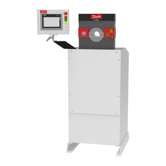
Machine description Design and function Basic machine (1) Crimping tool (2) Control cabinet (3) Unit (comprising electric motor, pump, control block) (4) Position encoder system (5) Control panel with buttons and control system CONTROL C.2 The crimping tool (1) is closed hydraulically, whereby the workpiece is formed. -
Page 21: Accessories
Data records may be saved in the item memory and recalled at any time in the control system. Depending on the operation mode, the ac- tual forming process is controlled via the buttons on the control panel (5), the depth stop or the dual foot switch. Crimping tool The die system comprises basic dies and crimping dies. -
Page 22: Forming Process
Forming process There are two types of forming process with different target parame- ters: • Forming to a defined diameter • Forming to a defined pressure Forming to a defined diameter This is the standard process for forming to produce hydraulic hoses. The crimping tool closes until it reaches a pre-set diameter, regar- dless of the required forming force. - Page 23 WARNING! Risk of injuries! In particular non-metal workpieces may by overstressed by the forming process so that this may result in a sudden failure. Chips or seriously accelerated workpiece parts impose a high risk po- tential for operators, individuals and objects, even outside the working area! •...
-
Page 24: Operation And Display Elements C.2
Operation and display elements C.2 (1) Emergency-stop button (2) Illuminated Motor on button (3) Motor off button (4) Illuminated foot switch (5) Illuminated Open tool button (6) Illuminated Close tool button (7) Locking lever / angle setting (8) control panel of CONTROL C.2 The illuminated buttons may be arranged the other way round, depending on the control version. -
Page 25: Electric Sockets
(1) LAN socket for connection with a network. Network connection options are set out in the description of the relevant optional packages. (2) 2 x USB sockets (for the use of memory media, callipers or bar- code scanners certified by UNIFLEX, only) Electric sockets (1) Main power switch (2) Socket for single foot switch... -
Page 26: Foot Pedal (Accessory)
Foot pedal (accessory) (1) Close machine pedal (2) Open machine pedal WARNING! Risk by fatiguing posture! A static posture may result in work-related musculosceletal disor- ders and reduce productivity. • Make sure that operators have sufficient periods of relief and recreation. -
Page 27: Depth Stop (Accessory)
Depth stop (accessory) (1) Angle clamp (2) Stop disc (3) Pressure spring (4) Clamp lever (5) Sleeve (6) Connection cable with plunger switch (7) Foot clamp (8) Clamp lever (9) Pipe (10) Cross clamp (11) Hollow profile Operation modes The control unit provides for the following operation modes for operat- ing the forming tool: •... - Page 28 is controlled manually via the buttons on the control panel or ex- ternal buttons (depth stop or dual foot switch): – Activate the button for closing and forming. The button is used for opening. – Dual foot switch The right foot switch is used for closing and forming. The left foot switch is used for opening.
- Page 29 The operation of the control system is described in a separate Op- eration Manual. This description is supplied with the machine.
-
Page 30: Technical Data
Technical data Machine Dimensions L x W x H 645 x 560 x 1450 mm Weight approx. 310 kg Control system CONTROL C.2 / IPC Operation mode S6-70% Noise level < 70 dB(A)* Degree of protection IP 40 Function Forming force 1320 kN / 135 t Max. - Page 31 Workpiece capacity SAE R13 1 Part Fitting 1 1/2", depending on fitting SAE R13 2 Part Fitting 1", depending on fitting SAE R12 2 Part Fitting 1 1/4", depending on fitting SAE R12 2 Part Fitting 1", depending on fitting Industry 2", without flange, depending on fit- ting...
- Page 32 Building prerequisites Permanent floor loading Approx. 0,07 kg/mm Floor carrying capacity Min. 2500 kg/m Floor quality Evenness Max. unevenness 5 mm/m Inclination max. 5 mm/m Ambient conditions C – 35 Ambient temperature 45% – 65% Air humidity The *data are theoretical/computed values, or values measured on a prototype.
-
Page 33: Transport And Commissioning
Transport and commissioning Transport The goods should be transported in the original packaging. During transport, the goods must be secured safely within the packaging. All applicable laws and regulations relating to securing loads shall be ob- served during transport. The machine/unit may only be unloaded and transported by means of a forklift, a lift truck or a crane. -
Page 34: Intermediate Storage Of Machine/Unit
WARNING! Danger from falling loads! Risk of injury from falling loads. • Do not stand under suspended loads. WARNING! Danger from tilting machine/unit! The machine/unit may tilt if it is transported improperly. There is a risk of being injured. • Consider the machine/unit's centre of gravity (1). -
Page 35: Filling Hydraulic Oil
WARNING! Risk by tilting machine! If not bolted to the floor, the machine may tilt. There is a risk of being injured. • Fix the machine on the floor. Use suitable bolts to fix the machine legs on the floor. Place the machine in a way so that it is easily accessible for main- tenance work from all sides. - Page 36 CAUTION! Risk of injuries! Contact with hydraulic oil and other consumables imposes a risk of injuries for the skin, eyes, respiratory and intestinal tracts! Hy- draulic liquid spills impose danger of slipping and falling! • Observe supplier's protection and safety instructions (see data sheet).
-
Page 37: Electrical Connection
Fill in hydraulic oil; for quantity and type, please refer to "Tech- nical data" in Section 3. The oil level can be read on the fill level indicator (3). The oil level should be at the centre of the fill level indicator. Close the bleed screw (2). - Page 38 Connect the voltage selection plug to the correct slot in the con- trol cabinet - Δ 230 V on connection (3), Υ 400 V on connection (2). Set the motor protection switch (1) as specified in Section 3, “Technical data”. The permissible voltage frequency ranges and the relevant motor protection setting are also indicated on the sticker in the control ca- binet door.
-
Page 39: Bleeding The Hydraulic System
Dismantle the control cabinet cover and check the electric motor rotational direction according to the arrow through the inspection window. Exchange outer cable (phases) of the connection, if re- quired. ATTENTION! Risk of damage to machinery! Extended operation of the motor with an incorrect rotational di- rection or operating the machine without oil will destroy the hyd- raulic pump. -
Page 40: Operation
Operation What you have to observe The operator has received the Operation Manual from the owner, has read and understood it and will observe it. Before starting and/or re-starting • Ensure sufficient illumination of the working area of the ma- chine/unit. -
Page 41: Forming The Workpiece
Forming the workpiece 5.3.1 Prerequisites Prerequisites for a correct forming process: • The die system and the workpiece match each other. • The proper jaw system is correctly mounted in the tool. • The forming dimension and the dies have been entered in the control system, please also refer to "Setting the forming dimen- sion"... - Page 42 WARNING! Risk of squeezing! When the die system closes, there is a risk of getting squeezed between the die and the workpiece. • Keep the feed opening for the workpiece as small as possi- ble. • Keep a minimum distance of 120 mm (A) to the die system. Manually position the pre-mounted workpiece in the tool.
-
Page 43: Remote Automatic Mode, Via Dual Foot Switch
5.3.3 Remote automatic mode, via dual foot switch WARNING! Risk of squeezing! When the die system closes, there is a risk of getting squeezed between the die and the workpiece. • Keep the feed opening for the workpiece as small as possi- ble. -
Page 44: Remote Automatic Mode, Via Depth Stop
actual dimension and the specified dimension (see "Setting the forming dimension" in Section 5). The operation mode Remote automatic via the dual foot switch is only functional if the plug of the dual foot switch is connected to the control cabinet. 5.3.4 Remote automatic mode, via depth stop WARNING! Risk of squeezing! -
Page 45: Changing The Crimping Dies With The Quick Die Change System (Only Profile 239)
Manual operation mode: Press the button to open the ma- chine when the forming process is completed. Semi-automatic operation mode: Wait until the hold time defi- ned in the control has expired; the tool will then open automati- cally. Remove the workpiece from the tool. Check the forming dimension after the first forming process. - Page 46 Rotate anti-clockwise and remove the crimping dies (2) from the deposit. Check the retaining bolts (3) of the crimping dies for damage. Hold the quick die change system with crimping dies in the cen- tre of the crimping tool. WARNING! Risk of squeezing! When the die system closes, there is a risk of getting squeezed between the dies.
-
Page 47: Adjusting The Depth Stop
ATTENTION! Risk of damage to machinery! If the crimping dies protrude beyond the basic and intermediate dies, the crimping dies, the intermediate dies and the machine will be damaged (see (X) in the figure). In the figure, the crimping die (2) is placed incorrectly. •... - Page 48 Mount the foot clamp (7) on the rear of the machine using cylin- der screw (6). WARNING! Risk of squeezing! There is risk of getting squeezed between the depth stop and the machine chassis when positioning the depth stop • Do not touch the stop in.
-
Page 49: Setting The Forming Dimension
Activate the illuminated foot pedal. The machine is closed automatically when the workpiece is pressed against the depth stop. Form the workpiece. Press the button to open the tool. Check the workpiece. If the workpiece meets the requirements: produce other identical workpieces. -
Page 50: Stop
Check the workpiece. If the dimension is reached: manufacture other identical workpie- ces. If the dimension is not reached: Adjust difference on control and/or in the micrometer, repeat the forming process and check the workpiece. Stop Complete the forming process. Deposit the work piece outside the machine. -
Page 51: Cleaning
Restart after and emergency WARNING! Risk of injuries! The emergency-stop button was probably activated due to the occurrence of a hazardous situation. A restart of the machine may cause injuries if the hazardous situation has not yet been remedied! • Remedy the hazardous situation before a restart. -
Page 52: Maintenance
Maintenance Regular maintenance will ensure the continuous operation reliability of the device. What you have to observe This Section describes action to be taken by you as the fitter regularly to ensure the troublefree use of the machine/unit. • Maintenance work may only be performed by qualified mainte- nance staff (machine/unit fitters). - Page 53 Maintenance item Hydraulic system Hydraulic energy lines – hoses: Check for porosity and leaks. Hydraulic energy lines - bolted connections of hoses and pipes: Check for leaks. Hydraulic oil: Check oil level, add oil if required (see “Replacing hydraulic oil” in Section 6). Hydraulic oil filter: Change according to control dis- play.
-
Page 54: Hydraulic Oil Change
Maintenance item Safety equipment Emergency-stop button: Check function Check permanently installed partitioning protection equipment and covers for completeness and correct installation. Check case foot switch for completeness. The case protects the pedals against unintentional activation. Warning signs on the machine: Check legibility (see "Warning signs on the machine"... - Page 55 ATTENTION! Risk of fire! Hydraulic liquid spray or spills imposes a risk of fire. • Avoid ignition sources (welding, cutting and soldering work) near the hydraulic oil filling. Deactivate the machine on the main switch and secure it against unintentional restart. Let the hydraulic oil cool down until the tank enclosure is warm to the touch.
-
Page 56: Checking And Replacing Slide Bearing Plates
14. Check oil level. The oil level should be at the centre of the fill level indicator; refill hydraulic oil, if required. Dispose of the oil in compliance with the applicable local environ- mental protection regulations. Checking and replacing slide bearing plates Checking slide bearing plates Check slide bearing plates for wear, replace defective parts. - Page 57 Open the crimping tool fully. Deactivate the machine on the main switch and secure it against unintentional restart. Loosen the hexagon socket screws (1) (four at the front and the back, each) and remove the protective plates (2). Loosen the hexagon socket screws (3) (eight at the front and the back, each) with adjusting washers and remove the guiding pla- tes (4).
-
Page 58: Replacement Of Relay/Opto-Coupler
Reassemble guiding plates and protective plates in the reverse order. 10. For this purpose, use grease to fix one adjusting washer, each, on the basedies before the guiding plates (4) are screwed on. 11. Perform a forming test run and check the formed sleeve. Shims, if any, have to be placed at the same location as before. - Page 59 Close flap.
-
Page 60: Troubleshooting
Troubleshooting Error Cause Remedy Machine does not close/open Main switch is OFF Activate the main switch Voltage incorrect Check voltage supply Power plug defective Check power plug and replace if necessary Rotational direction of electric Check rotation direction, cor- motor incorrect rect electrical connection Insufficient amount of hydrau- Refill oil... -
Page 61: Decommissioning, Disposal
Decommissioning, disposal WARNING! Risk by electrical voltage! There is a risk of electrocution near the live parts! • Shut down the machine/unit. • Disconnect the machine/unit from the power supply. CAUTION! Risk of injuries! Contact with hydraulic oil and other consumables imposes a risk of injuries for the skin, eyes, respiratory and intestinal tracts! Hy- draulic liquid spills impose danger of slipping and falling! •... -
Page 62: Dismantling
CAUTION! Risk of injuries! Parts of the machine/unit may be under pressure and/or tension. Loosening components may impose a risk of injuries! • De-pressurize the machine/unit before performing any work and check for potential sources of hazard. Dismantling This section describes activities to be performed by you as the opera- tor to ensure the safe dismantling of the machine/unit. - Page 63 Return consumables, e.g. oils, greases, test media, to supplier - they are hazardous waste. Also observe the information given on the safety data sheet.
-
Page 64: Annex
Annex Individual machine/unit components may deviate in their features. Please indicate the serial number of the machine for spare part or- ders. Accessories (retrofittable) Accessories Part code Quick die change system QDC 239.5 Die deposit QDS 239 B QDS 239 C QDS 239 R TU-QDS crimping die deposit system QDS-S.2 single row... -
Page 65: Spare Parts List
Spare parts list 9.2.1 Mechanical equipment Item Quantity Article code Designation 239.018.2 Upper yoke 239.019.2 Lower yoke 239.044.3 Beam 239.024.3 Tension rod... - Page 66 Item Quantity Article code Designation 239.300 Hydraulic cylinder 239.089.3 Tool plate 239.003.3 Basic dies 239.151 Pressure piece, spring-loaded 249.141 Compression spring 239.004.4 Lateral dies 239.008.4 Yoke disc 239.070.3 Oil collecting ring 6040 DU DU sleeves 239.010.4 Protective plate 239.011.4 Side bearing plate 239.012.4 Basic bearing plate 798.120006...
- Page 67 Position Number Article number Designation 255.1320.0 Chassis 255.103.4 Front panel HM 225 255.054.2 Cover 255.104.3 Protecting grating 239.020.3 Side cover HM 220 239.049.3 Protection cover 266.353 Oil inspection window 239.121.4 Position encoder angle 239.122.4 Position encoder angle SK 575.4 UNIFLEX sign...
- Page 68 Position Number Article number Designation 239.094.3 Blind plate 255.063.2 Gasket for vacuum plate 578.4 Oil prohibition sign 715.4 Squeezing risk warning sign 716.4 Warning of hand injuries sign 1.000 239.1520 Crimping tool, complete 1.001 1 set 239.14 Basic die set PB 239...
-
Page 69: Hydraulic System
9.2.2 Hydraulic system Item Quantity Article code Designation 239.220.2 Tank plate 264.325.3 Control block 239.308 Cartridge valve HM 220.3 227.001 Control valve... - Page 70 Item Quantity Article code Designation No fig. 220.916 Pressure sensor 24/30N2a-28 Hydraulic coupling 239.352 Pump 777.300 Pump carrier 777.301.3 Gasket GN 552-R3/4-A Bleed screw 239.517 Suction filter Re-suction filter 239.518 Double pipe nipple 238.604 Hydraulic hose 239.332 Hydraulic hose 255.062.2 Tank seal 238.619 Hose line...
-
Page 71: Electric Equipment
9.2.3 Electric equipment Item Quantity Article code Designation 807.700 CONTROL C.2 807.860 CONTROL IPC 807.415 Position encoder 8.06.100 Main power switch 888.621 Voltage selection unit 888.014 Motor protection combination... -
Page 72: Depth Stop, Manual
Item Quantity Article code Designation 807.318 Switching power supply 888.406 Passive interface 888.411 Relay 888.410 Opto-coupler 807.375 255.070.1 Electrical sheet, complete 807.453 Outside cable kit 238.011 Electric motor Depth stop, manual Item Quantity Part code Designation TA 220 Depth stop, manual, complete 239.008 Cross clamping piece with two clamping levers 239.009... -
Page 73: Depth Stop, Automatic
Item Quantity Part code Designation 239.011 Hollow profile 30x30x2 239.012 Pipe Ø 30x2 239.013 Circular plug 239.014 Square plug Depth stop, automatic Item Quantity Part code Designation TA HM 22x.3 C A Depth stop, automatic; complete 807.430 Plunger switch, complete 239.008 Cross clamping piece with two clamping levers 239.009... -
Page 74: Spare Parts Kit
Spare parts kit Quantity Part code Designation 239.1520 Replacement tool HM 220 239.4 Pressure spring 239.041.4 sw Retaining bolt, plastic (profile: 239 / 239L) 239.041.4 Retaining bolt, steel (profile: 239 / 239L) 239.151 Pressure spring screw(profile: 239) 239.8 Guiding plate set 239.7 Lateral die set 239.6... -
Page 75: Retaining Bolt For Standard Crimping Dies (Depending On Crimping Die)
Retaining bolt for standard crimping dies (depending on crimping die) Crimping die profile Retaining bolt 262.104.4 262.129.3 239.041.4 239.041.4 (sw) 232.504.4 Ø96 / Ø103 232.505.4 220.502.4... - Page 76 Crimping die profile Retaining bolt 245.114.4...
-
Page 77: Hydraulic Diagram
Hydraulic diagram... -
Page 78: Electric Diagram
Electric diagram... -
Page 87: Maintenance Log
Maintenance log Remark Date Signature ... -
Page 88: Declaration Of Qualified Staff
9.10 Declaration of qualified staff I herewith declare that I have attended an internal training for the operation of the UNIFLEX machine and have been informed on all safety-related details. In addition I declare that I have read and under- stood this Operation Manual completely.
Need help?
Do you have a question about the ET5020 and is the answer not in the manual?
Questions and answers