Table of Contents
Advertisement
Quick Links
Advertisement
Table of Contents

Related Manuals for Danfoss ET4100


Summary of Contents for Danfoss ET4100
- Page 2 Imprint Manufacturer: UNIFLEX-Hydraulik GmbH Robert-Bosch-Strasse 50-52 D-61184 Karben Germany Phone: +49 (0) 60 39 / 91 71 - 0 Fax: +49 (0) 60 39 / 91 71 - 181 This Operating Manual of the machine is a translation; the origi- nal is in German.
- Page 4 EC Declaration of Conformity In accordance with EC Machinery Directive 2006/42/EC. The following machine Danfoss ET4100 was developed, designed and manufactured in compliance with EC Directive 2006/42/EC, in the sole responsibility of UNIFLEX-Hydraulik GmbH Robert-Bosch-Strasse 50 - 52 D-61184 Karben The following standards, codes and specifications have been applied: •...
-
Page 5: Table Of Contents
Contents About this document................... 7 1.1 Target groups....................7 1.2 Storage ......................8 1.3 Name plate ....................9 1.4 Abbreviations ....................9 Safety instructions .................... 10 2.1 Presentation of warnings ................10 2.2 Intended use ....................10 2.3 Product-specific risks .................. 12 2.3.1 Risks imposed by mechanical equipment ........ - Page 6 5.3 Changing the crimping dies ................. 31 5.4 Setting the forming dimension ..............32 5.5 Completing the forming process ..............33 5.6 Emergency stop ................... 34 5.7 Cleaning ...................... 34 Maintenance ....................... 35 6.1 What you have to observe ................35 6.2 Maintenance schedule .................
-
Page 7: About This Document
About this document In this Operation Manual, the “forming machine Danfoss ET4100” is consistently referred to as machine. This Operation Manual includes important notes on how you operate your machine/unit safely, properly and economically. Use not in compliance with the intended purpose may result in hazard to the operator's health and life and/or in the risk of damage to/the machine/unit. -
Page 8: Storage
• persons working on the machine/unit are adequately qualified; • persons working on the machine/unit are suitable for operating the machine/unit; • the Operation Manual has been read and understood. One hard- copy of the Operation Manual must always be kept at a desig- nated place where the machine/unit is used. -
Page 9: Name Plate
Name plate The name plate is fixed on the machine back. Abbreviations Crimp Force Monitoring Manual Flow Divider Crimping dies Calibration crimping dies Pressure Force Control Pressure Force Monitoring Quick crimping die change system Intermediate dies... -
Page 10: Safety Instructions
Safety instructions Presentation of warnings Warning notes in the Operation Manual warn against risks involved with the handling of the machine/unit. Risk levels are identified as fol- lows: The signal word HAZARD identifies an imminent hazard resulting in HAZARD! serious injuries or death. This warning is supplemented by a triangu- lar hazard symbol. - Page 11 • use of eight identical original UNIFLEX dies with the same label or seven dies and one associated marking crimping die. • The machine must not be operated by persons not capable of operating the machine without any risk. These may include: ➢...
-
Page 12: Product-Specific Risks
Product-specific risks The machine/unit is designed in accordance with the latest state of technology. Nevertheless, the machine/unit may impose risks: 2.3.1 Risks imposed by mechanical equipment Risk of squeezing When the die system closes, there is a risk of getting squeezed between the die and the workpiece. -
Page 13: Risks Imposed By Substances
2.3.3 Risks imposed by substances Oils, greases and emulsions may penetrate the skin. When handling hazardous substances, oils and greases, the manufacturers' safety instructions have to be observed. Apply skin protection appropriate for the hazardous substances used. 2.3.4 Risks imposed by noise The noise level meter acc. -
Page 14: Safety
Safety 2.4.1 Working area The working area is defined as the area 1 metre all around the ma- chine (shaded). • Keep the working area free from trip hazards • Use ducts for lines and cables • Provide good illumination 2.4.2 Protection equipment Due to the variety of customer-specific workpieces, no additional standard protection equipment can be supplied with the machine that... - Page 15 large opening for being inserted into the forming machine. The pres- sure joining of insulators, structural steel and steel ropes, too, may re- quire special safeguards. The owner has to consider the need for adapted protection equip- ment before commissioning. If such need exists, the relevant protec- tion equipment has to be mounted before commissioning of the ma- chine.
-
Page 16: Warning Signs On The Machine
2.4.3 Warning signs on the machine Risk of crushing on the die system Risk of shearing on the die system Oiling / greasing prohibited on the die system Illegible or missing warning signs must immediately be replaced by the operator. -
Page 17: Machine Description
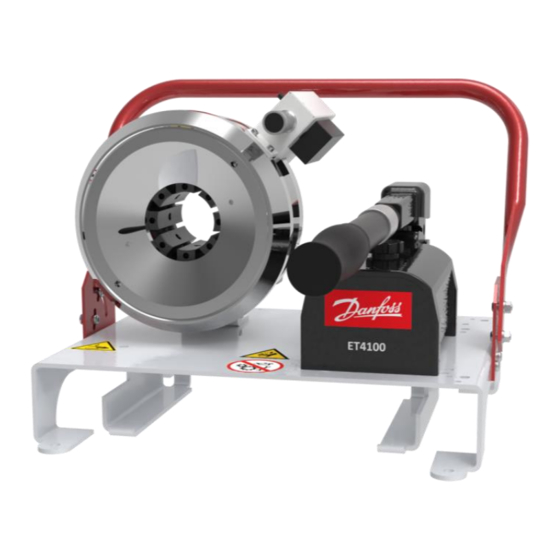
Machine description Design and function Base machine (1) Crimping tool (2) Micrometer (3) Signal lamp (4) Drainage valve hand wheel (5) Oil filling and drainage screw (6) Hydraulic hand pump (7) Pump handle The crimping tool (1) is closed hydraulically, whereby the work piece is formed. -
Page 18: Forming Process
The micrometer (2) is used to change the final diameter of the die system. Crimping tool The die system comprises base dies and crimping dies. All base dies are mounted on sliding plates (1). The crimping dies are plugged onto the base dies (3). After the forming process, the base dies are pressed apart by the pressure springs (2) when the tool opens. - Page 19 regardless of the required forming force. The required forming force may be up to the machine's maximum capacity. WARNING! Risk of injuries! In particular non-metal workpieces may by overstressed by the forming process so that this may result in a sudden failure. Chips or seriously accelerated workpiece parts impose a high risk po- tential for operators, individuals and objects, even outside the working area!
-
Page 20: Technical Data
Technical data Machine Dimensions L x W x H 500 x 420 x 440 mm Machine weight approx. 30 kg Operation mode Short-time duty S2 Function Forming force 900 kN / 90 t Max. forming range Ø crimping dies + 8 mm (max. - Page 21 Work piece capacity SAE R12 / 4SP 1 Part fittings 1 ¼ ", depending on the fitting SAE R15 / 4SH 2 part fittings 1", depending on the fitting Industry 1 ¼ " 90° bend 1", depending on the fitting Die type Hydraulic system Oil volume...
- Page 22 Ambient conditions C – 35 Ambient temperature 45 % – 65 % Air humidity The * data are theoretical/computed values, or values measured on a prototype. Actual values may vary slightly, depending on the ma- chine.
-
Page 23: Transport And Commissioning
Transport and commissioning Transport The goods should be transported in the original packaging. During transport, the goods must be secured safely within the packaging. All applicable laws and regulations relating to securing loads shall be ob- served during transport. The machine can only be transported manually. For machine weight, please refer to "Technical data"... -
Page 24: Intermediate Storage Of Machine/Unit
WARNING! Danger from increased load weights! The machine has a weight of over 25 kg. • Transport the machine with two persons. • Use transport aids. Lift the machine manually and transfer it to the installation site. Intermediate storage of machine/unit If the machine/unit cannot be mounted immediately upon delivery, it must be protected against: •... -
Page 25: Mounting The Telescopic Handle
Check the machine for damage. Check the hydraulic piping for damage. Train the operating staff and record training sessions in “Decla- ration of trained staff”, Section 9. WARNING! Risk of injuries! Machine components might loosen during transport. Such com- ponents might be flung out during to the forming process. There is a risk of being injured. -
Page 26: Filling Hydraulic Oil
4.4.1 Filling hydraulic oil The UNIFLEX forming machine is delivered with hydraulic oil filling. Check the oil level. CAUTION! Risk of injuries! A spare capacity of 25 % in the pump tank must be considered. • Refill oil with completely extended cylinder. CAUTION! Risk of injuries! Contact with hydraulic oil and other consumables imposes a risk... - Page 27 ATTENTION! Risk of fire! Hydraulic liquid spray or spills impose a risk of fire. • Avoid ignition sources (welding, cutting and soldering work) near the hydraulic oil filling. 1. Open the oil filling screw / bleed screw (1). 2. Add hydraulic oil; for quantity and type, please refer to "Technical data"...
-
Page 28: Operation
Operation What you have to observe The operator has received the Operation Manual from the owner, has read and understood it and will observe it. Before starting and/or re-starting • Ensure sufficient illumination of the working area of the machine. During operation •... -
Page 29: Hand Pump Operation Mode
5.2.2 Hand pump operation mode WARNING! Risk of squeezing! When the die system closes, there is a risk of getting squeezed between the die and the work piece. • Keep the feed opening for the workpiece as small as possi- ble. - Page 30 Hand pump 262.3013 The drainage valve hand wheel (1) must be closed for forming. Open the oil filling screw / bleed screw (2) by a quarter turn to balance the air pressure in the oil tank. Manually position the pre-mounted work piece in the tool. Hold the work piece with one hand during the forming process.
-
Page 31: Changing The Crimping Dies
WARNING! Risk of squeezing! When the die system closes, there is a risk of getting squeezed between the die and the work piece. • Open the crimping tool only so much that the hose may be in- serted and/or removed easily. Changing the crimping dies Positioning the crimping dies Completely open the crimping tool. -
Page 32: Setting The Forming Dimension
Always use a complete set of equal crimping dies with the same identification and diameter. One set comprises eight crimping dies or seven crimping dies and one matching marking die. Removing the crimping dies Completely open the crimping tool. Slowly open the drainage valve hand wheel. WARNING! Risk of squeezing! When the die system closes, there is a risk of getting squeezed... -
Page 33: Completing The Forming Process
Select crimping dies with a smaller or the same diameter, e.g. Ø 17 mm, Place the crimping dies in the tool. Set the control and/or micrometer to the requested dimension: Control system: Forming dimension diameter Micrometer: Workpiece forming dimension less crimping die di- ameter Form the workpiece. -
Page 34: Emergency Stop
Emergency stop In case of an emergency Immediately open the drainage valve hand wheel in cases of emer- gency. Restart after and emergency Remedy the cause of the emergency stop. Cleaning ATTENTION! Risk of damage to machinery! If the machine is cleaned with a steam jet or compressed air, dirt and water may ingress in the machine and cause serious da- mage. -
Page 35: Maintenance
Maintenance Regular maintenance will ensure the continuous operation reliability of the machine. What you have to observe This section describes activities to be performed by you as the opera- tor at regular intervals to ensure smooth operation of the machine. •... - Page 36 Maintenance item Hydraulic oil: Check oil level, add oil if re- quired (see “Replacing hydraulic oil” in Sec- tion 6). Hydraulic oil: Replace Hydraulic hoses: Have replaced (DIN 20066) no later than six years after manu- facture (see label). Make sure that replacement hoses are of equivalent quality (high-pressure hoses).
-
Page 37: Hydraulic Oil Change
Hydraulic oil changes and wear part replacements must be rec- orded in the maintenance log! Hydraulic oil change CAUTION! Risk of injuries! Contact with hydraulic oil and other consumables imposes a risk of injuries for the skin, eyes, respiratory and intestinal tracts! Hyd- raulic liquid spills impose danger of slipping and falling! •... - Page 38 Let the hydraulic oil cool down until the tank enclosure is warm to the touch. Open the oil filling screw (1). Pump out hydraulic oil using an external pump. Add new hydraulic oil (see “Technical Data” in Section 3). Close the oil filling screw (1). Do not operate the machine for a minimum of four hours so that the dirt particles in the system can settle.
-
Page 39: Checking And Replacing Slide Bearing Plates
Checking and replacing slide bearing plates Checking slide bearing plates Check slide bearing plates for wear, replace defective parts. The slide bearing plate (1) is new, the slide bearing plate (2) is worn. ATTENTION! Risk of damage to machinery! Worn slide bearing plates may cause damage to the machine and result in forming dimension inaccuracies. -
Page 40: Micrometer Adjustment
Loosen bolts (1) on bearing plate (2). Remove the worn bearing plate (2). Insert the new bearing plate (2). Replace all eight bearing plates in this manner. Tighten screws (1). Shims, if present, have to be inserted at the same position as be- fore. -
Page 41: Replacing The Battery
Adjust the contact screw (2). 1.6 revolutions of the contact screw correspond to 1 mm change in the forming dimension. Remount the enclosure/front panel. Test the crimping process and readjust if necessary. Replacing the battery Loosen the two bolts on the lateral battery box. Replace the battery. -
Page 42: Troubleshooting
Troubleshooting Error Cause Remedy Machine does not close/open Insufficient amount of hydrau- Refill oil lic oil Drainage valve hand wheel not Close drainage valve hand closed completely wheel Hand pump defective Check hand pump Hand pump cannot hold pres- Hydraulic bolted connections Check hydraulic bolted con- sure leak... -
Page 43: Decommissioning, Disposal
Decommissioning, disposal CAUTION! Risk of injuries! Contact with hydraulic oil and other consumables imposes a risk of injuries for the skin, eyes, respiratory and intestinal tracts! Hy- draulic liquid spills impose a danger of slipping and falling! • Observe supplier's protection and safety instructions (see data sheet). -
Page 44: Recycling
• Open the machine/unit completely. • Disconnect the machine/unit from the compressed air supply. • Depressurise the machine/unit before dismantling it (deactivate the hydraulic pump and secure it against restart; operate valve manually, if any; open bolted hydraulic connections slowly and carefully). -
Page 45: Annex
Annex Individual machine/unit components may deviate in their features. Please indicate the serial number of the machine for spare part or- ders. -
Page 46: Machine Overview
Machine overview... -
Page 47: Accessories (Retrofittable)
Accessories (retrofittable) Accessories Part code Camera set OCS 10.3 retro Lamp with magnetic base Universal table QDS 26x B Crimping die case PB 263 Crimping dies Please contact our Sales department for ordering accessories. -
Page 48: Spare Parts List
Spare parts list 9.3.1 Tool Item Quantity Part code Designation 262.010.1 Piston 262.212.2 Cylinder case 262.2 Gasket set S2 262.8 Base jaw set... - Page 49 Item Quantity Part code Designation 262.130 Pressure spring 262.036 Pressure spring screw 262.034 Pressure spring 262.015.2 Front plate 262.1015 Hollow piston tool 262.023.4 Guide pin 262.021.3 Bearing plate, front plate 262.371.4 Rotation lock holder 262.020.4 Piston bearing plate 262.025.4 Spacer plate...
-
Page 50: Mechanics And Pneumatics
9.3.2 Mechanics and Pneumatics Item Quantity Part code Designation 262.063.2 RAL 7035 Base plate 262.264.4 Mounting bracket 262.226.4 Bracket 262.232.3 RAL 7047 Protective cover 262.221.4 Limit switch holder... -
Page 51: Spare Parts Kit
Item Quantity Part code Designation 262.067.3 Clamp 262.066.4 Retaining plate 262.3013 Hand pump kit 262.510 Telescopic handle T 113 Pushbutton 888.428 Electroluminescent diode 173259 Block battery, 9 Volt No figure 213.410.01 Limit switch No figure 8.12.022 Battery clip 266.400.3 Crimping micrometer 211.502.3 Uniflex round closing blank 578.4... -
Page 52: Retaining Bolt For Standard Crimping Dies (Depending On Crimping Die)
Retaining bolt for standard crimping dies (depending on crimping die) Crimping die profile Retaining bolt 262.104.4 262.129.3 239.041.4 239.041.4 (sw) 232.504.4 Ø96 / Ø103 232.505.4 220.502.4... - Page 53 Crimping die profile Retaining bolt 245.114.4...
-
Page 54: Hydraulic Diagram
Hydraulic diagram... -
Page 55: Maintenance Log
Maintenance log Remark Date Signature ... -
Page 57: Declaration Of Qualified Staff
Declaration of qualified staff I herewith declare that I have attended an internal training for the operation of the machine and have been informed on all safety-rela- ted details. In addition I declare that I have read and understood this Operation Manual completely.
Need help?
Do you have a question about the ET4100 and is the answer not in the manual?
Questions and answers