Extraflame COMFORT P70 AIR H49 User Manual
Hide thumbs
Also See for COMFORT P70 AIR H49:
- Assembly instructions manual (6 pages) ,
- Instruction manual (44 pages) ,
- User manual (44 pages)

Related Manuals for Extraflame COMFORT P70 AIR H49


Summary of Contents for Extraflame COMFORT P70 AIR H49
- Page 1 PelleT sTOves UseR MANUAl COMFORT P70 AIR H49 MADE ITALY design & production 004281145- Rev 000...
- Page 2 APPLY TECHNICAL DATA LABEL ENGLISH...
-
Page 3: Table Of Contents
WarNINGS ............................................. 4 SafEty ............................................4 routINE MaINtENaNcE ......................................6 INStaLLatIoN ..........................................7 PREPARATIONS FOR MAINTENANCE ..........................................7 DEtaILS of INSErto coMfort P70 aIr H49 ................................9 INStaLLatIoN INSErto coMfort P70 aIr H49 ..............................10 GENERAl .....................................................10 MINIMuM ClEARANCE ................................................10 INSTAllATION ...................................................11 LoWEr fraME .......................................... -
Page 4: English
We thank you for having chosen our company; our product is a great heating solution developed from the most advanced technology with top quality machining and modern design, aimed at making you enjoy the fantastic sensation that the heat of a flame gives, in complete safety. Warnings This instructions manual is an integral part of the product: make sure that it always accompanies the appliance, even if transferred to another owner... - Page 5 RECEIVED INSTRUCTIONS ON SAFE USE OF THE APPLIANCE AND THAT THEY UNDERSTAND THE INHERENT DANGERS. Š THE GENERATOR MUST NOT BE USED BY PERSONS (INCLUDING CHILDREN) WITH REDUCED PHYSICAL, SENSORY AND MENTAL CAPACITIES OR WHO ARE UNSKILLED PERSONS, UNLESS THEY ARE SUPERVISED AND TRAINED REGARDING USE OF THE APPLIANCE BY A PERSON RESPONSIBLE FOR THEIR SAFETY.
-
Page 6: Routine Maintenance
(STRONG WIND, FREEzING) SAFETY SYSTEMS MAY INTERVENE THAT SWITCH THE GENERATOR OFF. IF THIS OCCURS, CONTACT THE TECHNICAL AFTER-SALES SERVICE AND ALWAYS DISABLE THE SAFETY SYSTEMS. Š IN THE EVENT THE FLUE CATCHES FIRE, USE SUITABLE SYSTEMS FOR SUFFOCATING THE FLAMES OR REQUEST HELP FROM THE FIRE BRIGADE. -
Page 7: Installation
InstallatIOn general The flue gas exhaust and hydraulic connections must be carried out by qualified personnel who must issue installation conformity documentation compliant with national standards. The installer must provide the owner or person acting for him, according to the legislation in force, with the declaration of conformity, supplied with: 1) the use and maintenance manual of the appliance and of the system components (such as for example, the smoke ducts, chimney, etc.);... - Page 8 In the presence of type B gas appliances with intermittent operation not intended for heating, they must have their own aeration and/or ventilation opening. The air inlets must meet the following requirements: Š they must be protected with grids, metal mesh, etc., but without reducing the net useful section; Š...
-
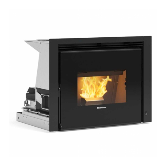
Page 9: Details Of Inserto Comfort P70 Air H49
DEtAIls oF INsERto CoMFoRt P70 AIR H49 Ambient air outlet Pellet hopper TA inlet Access to combustion chamber fuse 230V power supply and ash compartment Emergency module Rail Combustion air inlet fumes outlet Bulb thermostat rearm ENGLISH... -
Page 10: Installation Inserto Comfort P70 Air H49
INstAllAtIoN INsERto CoMFoRt P70 AIR H49 AssEMBly Must BE CARRIED out By quAlIFIED PERsoNNEl! GENERAl The insert is supplied with a sliding base in iron that allows it to be installed in a pre-existing chimney. This sliding base allows the insert to be removed easily to load the pellets inside the hopper and for any maintenance or cleaning at the end of the season. -
Page 11: Installation
INstAllAtIoN Open the door and release the latch using the poker supplied. Remove the 6 screws and release the chimney from the bottom and install the feed bracket. Fix the base to the existing flue pipe. AttENtIoN! REsPECt tHE 43MM HEIGHt FoR oPENING AND ClosING tHE INsERt CoRRECtly! ENGLISH... -
Page 12: Lower Frame
Fix the base to the kit if it is a new installation (optional kit). Block the rails with two screwdrivers and secure the flue pipe to the base with 6 screws. loWER FRAME The insert is equipped with a lower frame (optional assembly). To assemble it, see the instructions attached. Close the insert and block the latch. -
Page 13: Fresh Air Ducts
FREsH AIR DuCts for correct operation, air must be allowed to recirculate inside the structure that covers the insert in order to prevent the appliance from overheating. To guarantee this, just realise one or more openings in the lower and upper part of the covering. The following measurements must be respected: Š... -
Page 14: New Installation
NEW INstAllAtIoN EXAMPLE 1 EXAMPLE 2 A: Air convection outlet. Minimum section 120cm C: Air convection outlet. Minimum section 240cm B: air inlet from room. Minimum section 120cm D: air inlet from room. Minimum section 240cm for the insert to operate correctly, a minimum side of 20 mm and rear space of 12 mm must be guaranteed; the coatings must be made of non-flammable material. -
Page 15: Safety Latch
sAFEty lAtCH Use the poker supplied to perform the release/block operation. Use the holes on the two sides to remove the insert using pokers. Extraction of the insert allows both the pellets to be loaded inside the hopper and routine maintenance (cleaning the ash pipe at year end) or unscheduled maintenance (replacement of mechanical parts if the product should break) to be performed. -
Page 16: Extraction Of Insert And Pellet Loading
EXtRACtIoN oF INsERt AND PEllEt loADING Extraction of the insert allows both the pellets to be loaded inside the hopper and routine maintenance (cleaning the ash pipe at year end) or unscheduled maintenance (replacement of mechanical parts if the product should break) to be performed. To extract the insert, follow the procedure below: Open the fire door and slide the latch (using the poker supplied) to the unlocking position. -
Page 17: Optional Loading Accessories
oPtIoNAl loADING ACCEssoRIEs FRoNt PEllEt loADING KIt uPPER/sIDE PEllEt loADING KIt The optional pellet loading kit allows to load the pellets into the The optional pellet loading kit allows to load the pellets into the hopper from the front without having to remove the insert (which hopper without removing the insert from the installation opening would require the machine to be switched off ). -
Page 18: Emergency Module
emergency mODULe The stove is fitted with an emergency module located at the side, allowing the basic operation of the stove in the event the handheld remote is damaged or malfunctions. The functions that can be managed from the emergency module are: Key P1 Stove ignition/switch-off L1: Blue LED off:... -
Page 19: Radio Control
radio control configuration RAdIo conTRol devIce codIng pRocedURe: 1. disconnect the power supply to the stove. 2. press the keys at the same time until the RAdIo Id channel page appears 3. Using the buttons select the new RADIO ID channel (it is possible to select a RADIO ID channel between 0 and 63). 4. -
Page 20: Radio Control Device Features
radio control device featureS The radio control is fitted with an lcd backlit display. The display remains lit for 5 seconds. After a certain period of time, in order to minimise battery consumption, the display turns off (sleep mode). It turns on again after pressing the on/oFF key (6). CAUTION! do not place the radio control device in direct or indirect contact with water. -
Page 21: Display
diSplay SCREEN IN OPERATION STAND BY active chrono active Battery low power 1-5^ Time Tangential fan active Temperature detected in room Room SET THERMOSTAT set display text Tangential fan active in QUIET mode SCREEN WITH EXTERNAL THERMOSTAT CONNECTED TO THE TERMINAL “TA” Time Indicates the status of the contact of the external... -
Page 22: General Menu
general menu fUNCTION fUNCTION Scroll through parameters Back - exit key modify settings Ignition - switch-off key Access menu key MODE VENTILATION EASY SETUP CHRONO ENABLING CHRONO MODE PRG1 SETTINGS DATE/TIME PRG2 LANGUAGE PRG3 DISPLAY PRG4 STAND BY DELTA-T fIRST LOAD *STOVE STATUS DEGREES RESET... -
Page 23: First Ignition Settings
firSt ignition SettingS After connecting the power cord at the back of the generator, turn the switch (if any) to position (I). The switch is used to power the heat generator board. date/time This menu allows the date and time to be set. To set: oK >... -
Page 24: Operation And Logic
operation and logic ignition once the previously listed points have been checked, press key for three seconds to ignite the stove. during ignition, the stove will check for a flame for a period of 15 minutes. once the control temperature has been reached, the stove interrupts the ignition phase and switches to PREPARATION. -
Page 25: Modes
modeS This menu is used to set the operating logic of the machine for the power used. Range: (MANUAL, AUTOMATIC, AUX) By selecting MANUAL mode, the user can choose the heat output level delivered and the type of VENTILATION, according to his/her preferences. -
Page 26: Chrono
chrono This function allows stove ignition and switch-off to be automatically programmed. The factory setting for CHRONO is off. The chrono allows the programming of 4 time slots per day, which can be used every day of the week. in each time slot, it is possible to set the ignition and switch-off times, the days of use of the programmed time slot, the desired temperature (if automatic mode is used) and the set power. -
Page 27: Example
eXample chrono time Slot 02:00 08:00 16:30 23:00 manual 02:00 08:00 16:30 23:00 power Start 02:00 Time slot 1 power 5 Stop 23:00 02:00 08:00 16:30 23:00 Start 08:00 Time slot 2 power 1 02:00 08:00 16:30 23:00 Stop 16:30 22°... -
Page 28: Settings
SettingS Š DATE/TIME Š LANGUAGE See cHApTeR: commISSIonIng SeTTIngS. Š DEGREES diSplay The “DISPLAY" menu allows: Š Adjustment of display contrast. Š Activation/deactivation of backlight. Š enabling/disabling of acoustic signal. Š Setting of the timer to turn off the display backlight. Š... -
Page 29: Additional Thermostat Installation (Optional)
additional thermoStat inStallation (optional) The stove can control the room temperature through an additional thermostat (optional). After ignition (by pressing key 1 or in chrono mode), the stove will work to reach the set value on the thermostat, displaying WORk (closed contact) on the screen. -
Page 30: Radio Probe
The RADIO PROBE is an optional accessory that controls the temperature in the installation or ducting room without having to use wired sensors. For further details on its use and features, go to the website https://www.lanordica-extraflame.com/it depreSSure notice Allows the radio control buzzer to be activated for an acoustic warning if the door is opened. -
Page 31: Cleaning And Maintenance
Cleaning and maintenanCe always follow the instruCtions in Complete safety! Š Make sure that the power cord is unplugged because the generator May have been prograMMed to switch on. - Page 32 THE FOLLOWING IMAGES ARE FOR ILLUSTRATION PURPOSES burn pot and Combustion Chamber: Remove the burn pot completely from the Š relevant compartment. Once the flame guard (A) has been removed, Š vacuum the residue in the burn pot. Š Unblock all the holes in the burn pot using the supplied poker.
-
Page 33: Routine Maintenance Performed By Qualified Technicians
Qualified teChniCians routine maintenance must be performed at least once a year. - Page 34 heat exChanger ENGLISH...
- Page 35 routine maintenanCe THE IMAGES ARE FOR ILLUSTRATIVE PURPOSES. Fumes motor (dismantling and cleaning, flue pipe and "T” fitting). Gaskets, inspections, door (replace if necessary), burn pot and heat exchanger Combustion chamber and heat exchanger (full cleaning) including ignition plug pipe Hopper (complete emptying and cleaning).
-
Page 36: Displays
Displays upDate Reason Generator off START The START phase is in progress PELLET LOADING Continuous pellet feeding is in progress during the ignition state IGNITION The phase dedicated to ignition is in progress PREPARATION The flame stabilisation phase is in progress WORK The generator has reached operating capacity and is working on user settings MODULATION... -
Page 37: Disposal
Disposal InformatIon for management of electrIc and electronIc applIance waste contaInIng batterIes or accumulators This symbol, which is used on the product, batteries, accumulators or on the packaging or documents, means that at the end of its useful life, this product, the batteries and the accumulators included must not be collected, recycled or disposed of together with domestic waste. Improper management of electric or electronic waste or batteries or accumulators can lead to the leakage of hazardous substances contained in the product. - Page 38 ENGLISH...
- Page 39 ENGLISH...
- Page 40 CONTACT YOUR DEALER OR CONSULT THE SITE WWW.LANORDICA-EXTRAFLAME.COM The manufacturer reserves the right to vary the characteristics and the data reported in this pamphlet at any moment and without notice, in order to improve its products. 11/07/2022 004281145-000 MAN.UT. COMFORT P70 AIR H49...
Need help?
Do you have a question about the COMFORT P70 AIR H49 and is the answer not in the manual?
Questions and answers