
Subscribe to Our Youtube Channel
Related Manuals for mikroElektronika MIKROE-1575


Summary of Contents for mikroElektronika MIKROE-1575
- Page 1 mikromedia ™ for Tiva C Series ™ Compact multimedia development system rich with on-board peripherals TM4C123GH6PZ for all-round development on device...
- Page 2 TO OUR VALUED CUSTOMERS I want to express my thanks to you for being interested in our products and for having confidence in MikroElektronika. The primary aim of our company is to design and produce high quality electronic products and to constantly improve the performance thereof in order to better suit your needs.
-
Page 3: Table Of Contents
Table of Contents Introduction to mikromedia for Tiva C Series Programming with mikroProg programmer ™ ™ Package Contains 4. Reset Button Key Features 5. Crystal oscillator System Specification 6. MicroSD Card Slot 1. Power supply 7. Touch Screen Battery power supply 8. -
Page 4: Introduction To Mikromedia For Tiva ™ C Series
Introduction to mikromedia for Tiva C Series ™ mikromedia for Tiva C Series is a compact ™ development system with lots of on-board peripherals which allow development of devices with multimedia contents. The central part of the system is a 32-bit Cortex -M4 TM4C123GH6PZ microcontroller. -
Page 5: Package Contains
Package Contains Damage resistant mikromedia for Tiva C Series Two 1x26 male headers ™ protective box development system and one 1x5 header mikromedia for Tiva C Series mikromedia for Tiva C Series USB cable ™ ™ user’s guide schematic and pinout Page 5... -
Page 6: Key Features
Key Features RESET button Connection Pads TFT 320x240 display USB MINI-B connector Charge indication LED Li-Polymer battery connector Power indication LED 3.5mm headphone connector Power supply regulator VS1053 Stereo mp3 coder/decoder Tiva C Series ARM Cortex -M4 TM4C123GH6PZ ™ ® ™... -
Page 7: System Specification
System Specification power supply Via USB cable (5V DC) power consumption 56 mA with erased MCU (when on-board modules are inactive) board dimensions 81.2 x 60.5 mm (3.19 x 2.38 inch) weight ~50g (0.11lbs) CAUTION: Electrostatic Sensitive Device Permanent damage may occur on devices subjected to high energy electrostatic discharges which readily accumulate on the human body or test equipment and can discharge without detection. -
Page 8: Power Supply
1. Power supply USB power supply MINI-B You can power up the board using the cable provided in the package. On-board voltage regulators provide the appropriate voltage levels to each component on the Power LED (GREEN) board. will indicate the Figure 1-1: Connecting USB power supply presence of a power supply. - Page 9 AVCC VCC-3.3V VCC-3.3V VCC-1.8V HDR1 HDR2 VCC-SYS 2.2uF 10uF 100nF Vout 100K AP7331-ADJ VREF-1.8 VCC-1.8V 27K4 VCC-BAT 100K 100nF VCC-USB 100K VSENSE VCC-BAT 100K PMEG3010ER BATT CONN DMP2160UW VCC-3.3V VCC-3.3V VCC-3.3V VCC-BAT VCC-SYS M1X26 M1X26 VCC-3.3V VCC-3.3V VCC-3.3V VCC-BAT VCC-SYS CHARGE E7 10uF VCC-3.3V...
-
Page 10: Tm4C123Gh6Pz Microcontroller
2. TM4C123GH6PZ microcontroller The mikromedia for Tiva C Series development board comes ™ with the ARM® Cortex -M4 TM4C123GH6PZ microcontroller. ™ 32-bit This high-performance microcontroller with its integrated modules and in combination with other on-board modules is ideal for multimedia applications. Key microcontroller features - Up to 100 DMIPS... -
Page 11: Programming The Microcontroller
3. Programming the microcontroller Figure 3-1: TM4C123GH6PZ Cortex ® ™ Microcontroller The microcontroller can be programmed in two ways: Over USB mikroBootloader Using mikroProg for Tiva or other external programmers ™ Page 11... -
Page 12: Programming With Mikrobootloader
Programming with mikroBootloader step 1 – Connecting mikromedia The microcontroller is preprogrammed with USB HID Bootloader, which can be used to upload new device firmware. To transfer firmware .HEX file from a PC to an MCU you need to use the mik- roBootloader USB HID application, which can be downloaded from: www.mikroe.com/downloads/get/2090/ mikrobootloader_tiva_tm4c123gh6p_v130.zip... -
Page 13: Step 2 - Browsing For .Hex File
step 2 – Browsing for .HEX file step 3 – Selecting .HEX file Figure 3-3: Browse for HEX Figure 3-4: Selecting HEX Browse for HEX Click the button and from a Select the .HEX file using the Open dialog window. pop-up window (Figure 3.4) choose the .HEX file Click the Open... -
Page 14: Step 4 - Uploading .Hex File
step 4 – Uploading .HEX file Figure 3-5: Begin uploading Figure 3-6: Progress bar In order to upload the .HEX file click the Monitor the upload process via the progress bar. Begin uploading button. Page 14... -
Page 15: Step 5 - Finish Upload
step 5 – Finish upload Figure 3-7: Restarting MCU Figure 3-8: mikroBootloader ready for next job Click the button after uploading is finished. The board will be automatically reset and after 5 seconds your new program will execute. Page 15... -
Page 16: Programming With Mikroprog ™ Programmer
Programming with mikroProg programmer ™ mikroProg programmer mikroProg Suite for ARM software. The external The microcontroller can be programmed with the external ™ ™ ® programmer is connected to the development system via JTAG/SWD connector. mikroProg is a fast USB 2.0 programmer with hardware ™... - Page 17 HDR2 VDDC VDDC VCC-3.3V VDDC 100nF VDDC VDDC TM4C123GH6PZ AVCC 100nF USBVBUS/PB1 VCC-3.3V VCC-3.3V USBID/PB0 VDDA VREFA+ VREFA- 22pF 10uF 100nF GNDA OSC1 OSC0 TM4C123GH6PZ 22pF RESET# VCC-3.3V VCC-3.3VVCC-3.3V M1X26 100nF 100nF VCC-3.3V TMS-PC1 VBAT TCK-PC0 VCC-3.3V VCC-3.3V XOSC1 10pF TDO-PC3 GNDX TDI-PC2...
-
Page 18: Reset Button
4. Reset Button Figure 4-2: Frontal reset button mikromedia for Tiva C Series is equipped with a reset button, which is located at the top of the front side (Figure 4-2). If you want to ™ reset the circuit, press the reset button. It will generate a low voltage level on the microcontroller reset pin (input). In addition, a reset can be externally provided through pin 27 on side headers (Figure 4-3). - Page 19 AVCC VDDC VCC-3.3V VCC-3.3V VDDC VDDC 100nF TM4C123GH6PZ VDDC VDDC 100nF USBVBUS/PB1 HDR2 USBID/PB0 VDDA VCC-3.3V VCC-3.3V VCC-3.3V VREFA+ VREFA- 22pF GNDA OSC1 OSC0 TM4C123GH6PZ 10uF 100nF 100nF 22pF VCC-3.3V VCC-3.3V VCC-3.3V 100nF 100nF 100nF VBAT XOSC1 10pF GNDX XOSC0 VCC-3.3V VCC-3.3V VCC-3.3V...
-
Page 20: Crystal Oscillator
5. Crystal oscillator Figure 5-1: 16MHz crystal oscillator mikromedia for Tiva C Series is equipped with a 16MHz ™ crystal oscillator (X1) circuit that provides an external clock waveform to the microcontroller OSC0 and OSC1 pins. This base frequency is suitable for further clock multipliers and is ideal for generation of the necessary USB clock, which ensures proper operation of bootloader and your custom USB-based applications. - Page 21 AVCC VDDC VCC-3.3V VDDC VDDC 100nF TM4C123GH6PZ VDDC VDDC 100nF USBVBUS/PB1 USBID/PB0 VDDA VREFA+ VCC-3.3V VCC-3.3V VCC-3.3V VREFA- 22pF GNDA OSC1 OSC0 TM4C123GH6PZ 22pF 10uF 100nF 100nF VCC-3.3V VCC-3.3V VCC-3.3V VBAT 100nF 100nF 100nF XOSC1 10pF GNDX XOSC0 10pF VCC-3.3V VCC-3.3V VCC-3.3V 100nF...
-
Page 22: Microsd Card Slot
6. microSD Card Slot Figure 6-1: microSD card slot mikromedia for Tiva C Series contains a microSD card slot for using microSD cards in your projects. It enables you to store large ™ amounts of data externally, thus saving microcontroller memory. MicroSD cards use Serial Peripheral Interface (SPI) for communication with the microcontroller. - Page 23 AVCC VDDC VCC-3.3V VDDC VDDC VDDC VDDC VCC-3.3V VCC-3.3VVCC-3.3VVCC-3.3VVCC-3.3V TM4C123GH6PZ 100nF 100nF 10uF 100nF 100nF 100nF 100nF VCC-3.3V VCC-3.3V VCC-3.3V VCC-3.3V USBVBUS/PB1 USBID/PB0 VDDA VREFA+ 100nF 100nF 100nF 100nF VREFA- 22pF GNDA OSC1 OSC0 TM4C123GH6PZ decoupling 22pF capacitors VCC-MMC VCC-3.3V FERRITE VBAT XOSC1...
-
Page 24: Touch Screen
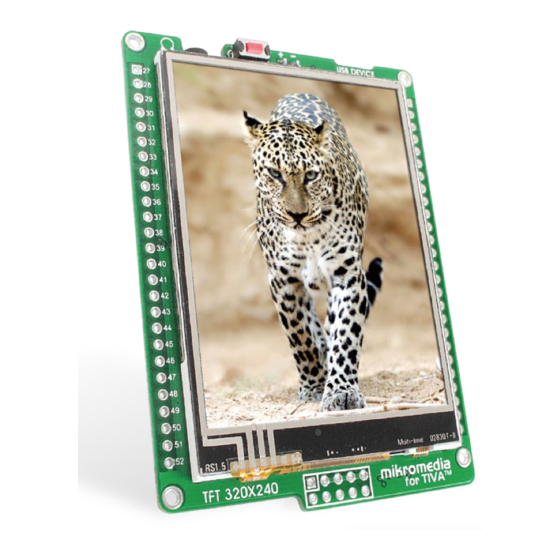
7. Touch Screen The development system features a TFT 320x240 display covered with a resistive touch panel. Together they form a functional unit called a touch screen. It enables data to be entered and displayed at the same time. The TFT display is capable of showing graphics in 262.144... - Page 25 VCC-SYS VCC-3.3V VCC-3.3V TFT1 AVCC VCC-3.3V LED-K VDDC LED-A1 LED-A2 LED-A3 BC846 LED-A4 LCD-BLED BC846 TM4C123GH6PZ LCD-RST RESET VSYNC HSYNC LCD-BLED VCC-3.3V DOTCLK BC846 ENABLE T-D7 DB17 10uF T-D6 USBVBUS/PB1 DB16 T-D5 USBID/PB0 DB15 T-D4 VDDA DB14 T-D3-PF3 VREFA+ DB13 VCC-3.3V VCC-3.3V T-D2-PF2...
-
Page 26: Audio Module
8. Audio Module mikromedia for Tiva C Series features a stereo audio codec VS1053. This module ™ enables audio reproduction by using stereo headphones connected to the system via a 3.5mm connector CN1. All functions of this module are controlled by the microcontroller over Serial Peripheral Interface (SPI). - Page 27 VDDC VDDC VDDC VDDC VCC-3.3V VCC-3.3VVCC-3.3VVCC-3.3VVCC-3.3V VCC-3.3V VCC-3.3V VCC-3.3V VCC-3.3V decoupling AVCC VCC-3.3V VDDC capacitors 100nF 100nF 10uF 100nF 100nF 100nF 100nF 100nF 100nF 100nF 100nF TM4C123GH6PZ HDR2 10uF VCC-1.8V VCC-3.3V 3.3nF 100K USBVBUS/PB1 USBID/PB0 VDDA 10uF VREFA+ VREFA- 22pF GNDA OSC1 OSC0...
-
Page 28: Usb Connection
9. USB connection Figure 9-1: Connecting USB cable to MINI-B USB connector Cortex -M4 TM4C123GH6PZ microcontroller has an integrated USB module, which ® ™ enables you to implement USB communication functionality to your mikromedia board. Connection with target USB host is done over MINI-B USB connector which is positioned next to the battery connector. Page 28... - Page 29 AVCC VDDC VCC-3.3V VCC-USB FERRITE R40 100 USB-DET VBUS USB-D_N USB-D_P USB-ID TM4C123GH6PZ 100K 10nF USB MINIB USB-DET USBVBUS/PB1 USB-ID USBID/PB0 USB-D_P VDDA USB-D_N VREFA+ VREFA- 22pF VDDC VDDC VDDC VDDC VCC-3.3V GNDA OSC1 OSC0 TM4C123GH6PZ 22pF 100nF 100nF 10uF VCC-3.3V VCC-3.3V VCC-3.3V...
-
Page 30: Accelerometer
10. Accelerometer Figure 10-1: Accelerometer module ADXL345 On-board accelerometer is used to measure acceleration in three axes: x, y and z. The accelerometer function is defined by the user in the program loaded into the microcontroller. Communication between the accelerometer and the microcontroller is performed via the interface. - Page 31 AVCC VDDC VCC-3.3V VCC-3.3V VCC-3.3V SCL0-PB2 TM4C123GH6PZ SDA0-PB3 ACC ADDRESS SDA0-PB3 VCC-3.3V SCL0-PB2 INT2 USBVBUS/PB1 INT1 USBID/PB0 VDDA ADXL345 VREFA+ VREFA- 22pF GNDA OSC1 VCC-3.3V VCC-3.3V OSC0 TM4C123GH6PZ 22pF 100nF 100nF decoupling capacitors VDDC VDDC VDDC VDDC VBAT XOSC1 10pF GNDX XOSC0 100nF...
-
Page 32: Flash Memory
11. Flash Memory Figure 11-1: Flash memory module Since multimedia applications are getting increasingly demanding, it is necessary to provide additional memory space to be used for storing more data. The flash memory module enables the microcontroller to use additional 8Mbit flash memory. - Page 33 AVCC VCC-3.3V VDDC VCC-3.3V VCC-3.3V 100nF TM4C123GH6PZ FLASH-CS# MISO0-PA4 HOLD SCK0-PA2 R12 27 MOSI0-PA5 M25P80 USBVBUS/PB1 USBID/PB0 decoupling VDDA capacitors VREFA+ VREFA- 22pF GNDA OSC1 VDDC VDDC VDDC OSC0 TM4C123GH6PZ 22pF 100nF VDDC VCC-3.3V VCC-3.3V VBAT XOSC1 10pF 100nF GNDX 10uF 100nF XOSC0...
-
Page 34: Pads
12. Pads VCC-SYS HDR1 AVCC VDDC VCC-3.3V AN-PD5 AN-PD6 AN-PD7 AN-PE3 AN-PE2 AN-PE1 TM4C123GH6PZ AN-PE0 INT-PH0 HDR2 INT-PH1 SCK1-PD0 LCD-BLED INT-PH2 INT-PH3 MISO1-PD2 SDA0-PB3 MOSI1-PD3 SCL0-PB2 SCL2-PG0 PWM-PH4 USBVBUS/PB1 SDA2-PG1 PWM-PH5 USBID/PB0 PWM-PH6 VDDA SCK1-PD0 VREF-1.8 PWM-PH7 VREFA+ MISO1-PD2 VREFA- 22pF MOSI1-PD3 GNDA... -
Page 35: Pinout
13. Pinout System power supply Reset pin VSYS Reference Ground Reference Ground left ch. audio out right ch. Analog Lines PWM lines Interrupt Lines Digital I/O lines Digital I/O lines UART Lines SCL2 SPI Lines C Lines SDA2 3.3V 3.3V power supply 3.3V power supply 3.3V Reference Ground... -
Page 36: Dimensions
14. Dimensions 81.15 3195 73.66 2900 63.5 2500 2.54 2.67 Legend 57.6 2268 69.3 2728 Page 36... -
Page 37: Mikromedia Accessories
15. mikromedia accessories We have prepared a set of extension boards pin-compatible with your mikromedia, which enable you to easily expand your board’s basic functionality. call them mikromedia shields. But we also offer other accessories, such as Li-polymer battery, stacking headers, wire jumpers and more. -
Page 38: What's Next
What’s next? You have now completed the journey through each and every feature of mikromedia for Тiva C Series board. You got to know its modules and ™ organization. Now you are ready to start using your new board. We are suggesting several steps which are probably the best way to begin. Find useful projects and tutorials on the Libstock website (http://www.libstock.com/). - Page 39 No part of this manual, including product and software described herein, may be reproduced, stored in a retrieval system, translated or transmitted in any form or by any means, without the prior written permission of MikroElektronika. The manual PDF edition can be printed for private or local use, but not for distribution.
- Page 40 If you want to learn more about our products, please visit our website at www.mikroe.com If you are experiencing some problems with any of our products or just need additional information, please place your ticket at www.mikroe.com/support If you have any questions, comments or business proposals, mikromedia for Tiva C Series Manual ver.
Need help?
Do you have a question about the MIKROE-1575 and is the answer not in the manual?
Questions and answers