VeriFone e355 Installation Manual
Hide thumbs
Also See for e355:
- User and best practices manual (78 pages) ,
- User manual (60 pages) ,
- Installation manual (43 pages)
Table of Contents
Advertisement
Quick Links
Advertisement
Table of Contents

Related Manuals for VeriFone e355


Summary of Contents for VeriFone e355
- Page 1 Installation Guide Verifone Part Number DOC087-063-EN-A, Revision A.2...
- Page 2 Verifone, Inc. The information contained in this document is subject to change without notice. Although Verifone has attempted to ensure the accuracy of the contents of this document, this document may include errors or omissions. The examples and sample programs are for illustration only and may not be suited for your purpose.
-
Page 3: Table Of Contents
Examining e355 Device Features........11... - Page 4 H AP T ER Verifone Service Returning a Device for Service........27 and Support Accessories and Documentation .
-
Page 5: Preface
REFACE This guide is your primary source of information for setting up the e355. Audience This guide is useful for anyone installing an e355 device. Basic descriptions of the device features are also provided. Organization This guide is organized as follows:... -
Page 6: Conventions And Acronyms
Europay MasterCard and VISA Liquid Crystal Display Light Emitting Diode Near Field Communication Merchandise Return Authorization MSAM Micromodule-Size Security Access Module Payment Card Industry PIN Entry Device Personal Identification Number Subscriber Identity Module Universal Serial Bus Verifone Part Number 355 I NSTALLATION UIDE... -
Page 7: Hapter
Device Overview This chapter provides a brief description of the e355. The e355 connects with various tablet devices for the next generation of PAYware Mobile enterprise. It supports the use of the SPP standard to connect between the e355 and tablet. -
Page 8: Features And Benefits
• The e355 size is easily able to be dropped in most pockets. An optional hands-free holster is available that fits the server’s or clerk’s belt so that the e355 can be quickly removed and easily handed to the customer. -
Page 9: Hapter
Examining e355 Device Features • Installing/Replacing an MSAM Card • Manually Starting and Resetting the e355 • Connecting the e355 to a Power Source or a Host Computer • Color Behavior • Using the Smart Card Reader • Using the Magnetic Stripe Reader •... -
Page 10: Usage Guidelines
Unpacking the Open the shipping carton and carefully inspect its contents for possible tampering Shipping Carton or shipping damage. The e355 is a secure product and any tampering may cause the device to cease to function properly. To unpack the... -
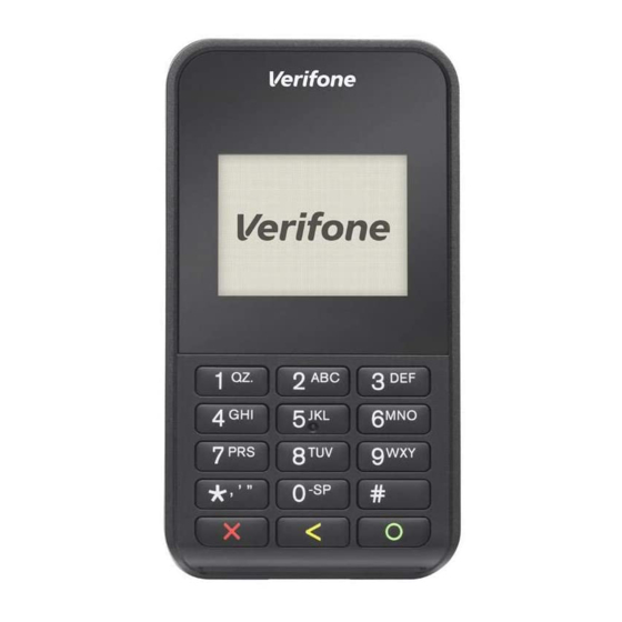
Page 11: Examining E355 Device Features
ETUP Examining e355 Device Features Remove the clear protective film from the unit. Do not use a unit that has been damaged or tampered with. The e355 comes CAUTION equipped with tamper-evident labels. If a label or component appears damaged or if the device appears to have been opened, please notify the shipping company and your Verifone representative or service provider immediately. - Page 12 • A Micro-USB port located on the right side for data connection and power charging. You can also use this connect the e355 to a computer using a standard USB to Micro-USB cable (VPN CBL000-049-01-A). (See Connecting...
-
Page 13: Back View
(See Using the Barcode Reader) Installing/Replacing When you first receive your e355, you may need to install an MSAM card or you an MSAM Card may need to replace an old card. Observe standard precautions when handling electrostatically sensitive devices. - Page 14 EVICE ETUP Examining e355 Device Features To install/replace Unplug any cables or chargers from the e355. MSAM Remove the screw from the battery cover. Slide the cover outwards, away from the device. Remove the battery by gently pulling the plastic tab to access the MSAM compartment.
-
Page 15: Manually Starting And Resetting The E355
ETUP Examining e355 Device Features Manually Starting To turn on the e355, press and hold the Enter key for at least five seconds. and Resetting the The Reset Button is located between the right Barcode Button and Power LED e355 Indicator. -
Page 16: Color Behavior
ETUP Examining e355 Device Features To Connect the e355 Connect the Micro-USB cable into the port located on the side of the e355. to a Host Computer Connect the other end of the Micro-USB cable into the host computer’s USB via Micro-USB port. -
Page 17: Using The Smart Card Reader
EVICE ETUP Examining e355 Device Features Using the Smart The smart card transaction procedure may vary from one application to another. Card Reader Verify the procedure with your application provider before performing a smart card transaction. To conduct a smart... -
Page 18: Using The Ctls Reader
IMAGE PLACEHOLDER ACTUAL ILLUSTRATION TO FOLLOW Figure 10 Using the CTLS reader Using the Barcode The Barcode buttons located on either side of the e355, activate the barcode Reader reader (see Figure 3). Press either button to scan barcodes. IMAGE PLACEHOLDER... -
Page 19: Examining E355 Frame Features
A Removable Module that serves as a locking attachment for the tablet and the e355 frame. • A Locking Screw on the upper left side of of the e355 Frame back panel to secure the tablet and the Removable Module. NOTE The locking screw is captive, which means that it cannot be fully removed from the slot. -
Page 20: Attaching The E355 Device To The E355 Frame
A Tablet Connector to connect the e355 Frame to an Apple, Android, or Windows tablet. Attaching the e355 The e355 can be used both as a standalone device or connected to an e355 Device to the e355 Frame. When a tablet is connected to e355 Frame, the payment application in the Frame tablet can utilize the e355 device to perform payment transactions. -
Page 21: Connecting The E355 Frame To A Power Source
Eject Button to the right. Carefully pull the tablet upwards to disengage it from the e355 Frame. Place the Removable Module back by guiding the pins to the slots on the e355 Frame. Turn the locking screws clockwise. - Page 22 EVICE ETUP Examining e355 Frame Features 355 I NSTALLATION UIDE...
-
Page 23: Hapter
Specifications This chapter discusses power requirements, dimensions, and other specifications of the e355 device. Power Charging via Micro-USB to computer system or Verifone-certified power adapter: 5 V DC, 2 A Temperature • Operating Temperature: -5° to 40°C (23° to 104°F) •... - Page 24 PECIFICATIONS External Dimensions 355 I NSTALLATION UIDE...
-
Page 25: Maintenance
Do not spray cleaners or other solutions directly onto the keypad or device display. Smart Card Do not attempt to clean the smart card reader. Doing so may void any warranty. Reader For smart card reader service, contact your Verifone distributor or service provider. 355 I NSTALLATION UIDE... - Page 26 AINTENANCE Smart Card Reader 355 I NSTALLATION UIDE...
- Page 27 NOTE representative for assistance regarding service, return, or replacement of devices and accessories. To return a device for Get the following information from the printed labels at the back of each e355 service to be returned: • Product ID, including the model and part number. For example, “e355” and “M087-XXX-XXX-XXX.”...
-
Page 28: And Support Accessories And Documentation
• Reference the model and part number in the Note box. NOTE One MRA number must be issued for each e355 you return to Verifone, even if you are returning several of the same model. Describe the problem(s). Provide the shipping address where the repaired or replacement unit must be returned. -
Page 29: Hapter
Device Display • Recharge the battery. Does Not Show • Connect the e355 into a known-good power supply (if available) to see if this Correct/ clears the problem. Readable Info • If the problem persists, contact your local Verifone representative for assistance. -
Page 30: Blank Display
ROUBLESHOOTING UIDELINES Blank Display Blank Display When the e355 display screen does not show correct or clearly readable information: • Check device power connection. • Remove and reapply power to the device. To do this, press and hold the power/reset button. - Page 31 ROUBLESHOOTING UIDELINES Transactions Fail To Process • Contact your Verifone distributor or service provider. 355 I NSTALLATION UIDE...
- Page 32 Verifone, Inc. 2099 Gateway Place, Suite 600 San Jose, CA, 95110 USA 1-800-VERIFONE www.verifone.com e355 Installation Guide Verifone Part Number DOC087-063-EN-A, Revision A.2...
- Page 33 Federal Communication Commission Interference Statement This device complies with Part 15 of the FCC Rules. Operation is subject to the following two conditions: (1) This device may not cause harmful interference, and (2) this device must accept any interference received, including interference that may cause undesired operation.
- Page 34 Radiation Exposure Statement: This device meets the government’s requirements for exposure to radio waves. This device is designed and manufactured not to exceed the emission limits for exposure to radio frequency (RF) energy set by the Federal Communications Commission of the U.S. Government. The exposure standard for wireless device employs a unit of measurement known as the Specific Absorption Rate, or SAR.
- Page 35 Industry Canada statement This device complies with Industry Canada license-exempt RSS standard(s). Operation is subject to the following two conditions: (1) this device may not cause interference, and (2) this device must accept any interference, including interference that may cause undesired operation of the device.
- Page 36 sélection de l'indicatif du pays est désactivée pour les produits commercialisés aux États-Unis et au Canada. Caution : (i) the device for operation in the band 5150-5250 MHz is only for indoor use to reduce the potential for harmful interference to co-channel mobile satellite systems; (ii) the maximum antenna gain permitted for devices in the bands 5250-5350 MHz and 5470-5725 MHz shall comply with the e.i.r.p.
Need help?
Do you have a question about the e355 and is the answer not in the manual?
Questions and answers