Grundfos LC 108 Installation And Operating Instructions Manual
Hide thumbs
Also See for LC 108:
- Installation and operating instructions manual (54 pages) ,
- Installation and operating instructions manual (204 pages)
Table of Contents
Advertisement
Advertisement
Table of Contents

Related Manuals for Grundfos LC 108


Summary of Contents for Grundfos LC 108
- Page 1 GRUNDFOS INSTRUCTIONS LCD 108 Installation and operating instructions...
- Page 2 Declaration of Conformity We, Grundfos, declare under our sole responsibility that the product LC/LCD 108, to which this declaration relates, is in conformity with these Council directives on the approximation of the laws of the EC member states: — Machinery Directive (98/37/EC).
-
Page 3: Table Of Contents
CONTENTS 1.1 Applications The LCD 108 enables: Page • control of two pumps based on signals from float switches, General Applications • automatic pump changeover (even distribution of operating Variants hours on both pumps), • selection of automatic test run during long periods of inactivity Location and mounting Location (every 24 hours),... -
Page 4: Location
Note: Cables of up to 100 metres can be connected between the Float switches placed in an explosion hazard area controller and the float switches. must be connected via an EEx barrier, e.g. Grundfos number 96440300. The EEx barrier must not be installed in the explosion hazard area. -
Page 5: Setting
Note: Float switches of the same type as Grundfos product At this setting, the start-up is delayed within the range number 96003332 or 96003695, i.e. float switches with from 0 to 255 sec. (random) after the electricity supply gold-plated contacts suitable for low voltages and currents (40 V/ has been switched on when the liquid level is 100 mA), must be used. - Page 6 AC/DC selector: The AC/DC selector switch for electrodes and/or float switches is placed as shown in fig. 3. Fig. 3 Operation with electrodes and float switches: Selector switch in position AC: It is possible to connect 3 13-18 VAC electrodes (1 as reference electrode) and 2 float switches.
-
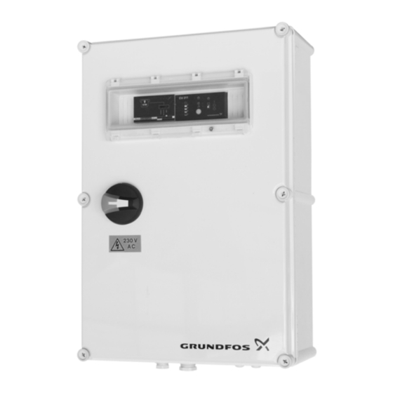
Page 7: Control Panel
The table below shows the situations which may occur if the 3.3 Control panel normal electricity supply to the LCD 108 fails and a back-up Parallel operation with 3 float switches, pages 23 and 24. battery is connected: Figure 4 shows the control panel of the CU 212 module. = the indicator light is off. -
Page 8: Reset Button And On-Off-Auto Selector Switch
Float switches placed in an explosion hazard area position 0. must be connected via an EEx barrier, e.g. Grundfos Any external voltage connected to the system must number 96440300. be switched off before work is started. -
Page 9: Setting
Note: Float switches of the same type as Grundfos product • Switch 4, starting delay and automatic test run number 96003332 or 96003695, i.e. float switches with (only in the case of battery back-up): gold-plated contacts suitable for low voltages and currents (40 V/ When the DIP switch setting is changed, the controller must 100 mA), must be used. -
Page 10: Control Panel
AC/DC selector: 4.3 Control panel The AC/DC selector switch for electrodes and/or float switches is Parallel operation with 4 float switches, pages 25 and 26. placed as shown in fig. 6. Figure 7 shows the control panel of the CU 212 module. 2 3 4 CU 212 Fig. -
Page 11: Battery Back-Up Functions
4.4 Battery back-up functions Parallel operation with 4 float switches, pages 25 and 26. If a back-up battery for CU 212 (accessory for certain variants) is installed, the following functions will be carried out if the normal electricity supply to the LCD 108 fails (see also the illustrations below): •... -
Page 12: Reset Button And On-Off-Auto Selector Switch
4.5 Reset button and ON-OFF-AUTO selector switch Parallel operation with 4 float switches, pages 25 and 26. The reset button is a push-button for manual resetting of alarm signals to external alarm devices and the built-in buzzer (i.e. not for resetting of the alarm memory as this is reset by means of the ON-OFF-AUTO selector switch, see position OFF ( )). -
Page 13: Systems For 100 % Standby Operation
Furthermore, the cables into the explosion hazard area must be laid in accordance with local regulations. Note: Float switches of the same type as Grundfos product number 96003332 or 96003695, i.e. float switches with gold-plated contacts suitable for low voltages and currents (40 V/100 mA), must be used. - Page 14 • Switch 4, starting delay and automatic test run AC/DC selector: (only in the case of battery back-up): The AC/DC selector switch for electrodes and/or float switches is When the DIP switch setting is changed, the controller must placed as shown in fig. 9. be switched off for at least 1 minute! At this setting, the start-up is delayed within the range from 0 to 255 sec.
-
Page 15: Control Panel
5.3 Control panel 5.4 Battery back-up functions 100 % standby operation, pages 25 and 26. 100 % standby operation, pages 25 and 26. Figure 10 shows the control panel of the CU 212 module. If a back-up battery for CU 212 (accessory for certain variants) is installed, the following functions will be carried out if the normal electricity supply to the LCD 108 fails (see also the illustrations 2 3 4... -
Page 16: Reset Button And On-Off-Auto Selector Switch
5.5 Reset button and ON-OFF-AUTO selector switch 100 % standby operation, pages 25 and 26. The reset button is a push-button for manual resetting of alarm signals to external alarm devices and the built-in buzzer (i.e. not for resetting of the alarm memory as this is reset by means of the ON-OFF-AUTO selector switch, see position OFF ( )). -
Page 17: System For Full-Control Operation
Furthermore, the cables into the explosion hazard area must be laid in accordance with local regulations. Note: Float switches of the same type as Grundfos product number 96003332 or 96003695, i.e. float switches with gold-plated contacts suitable for low voltages and currents (40 V/100 mA), must be used. - Page 18 • Switch 4, starting delay and automatic test run • Switch 10, automatic restarting: (only in the case of battery back-up): When the DIP switch setting is changed, the controller must When the DIP switch setting is changed, the controller must be switched off for at least 1 minute! be switched off for at least 1 minute! This setting enables automatic restarting after the PTC...
-
Page 19: Control Panel
6.3 Control panel 6.4 Battery back-up functions Full-control operation, pages 29 and 30. Full-control operation, pages 29 and 30. Figure 13 shows the control panel of the CU 212 module. If a back-up battery for CU 212 (accessory for certain variants) is installed, the following functions will be carried out if the normal electricity supply to the LCD 108 fails (see also the illustrations 2 3 4... -
Page 20: Reset Button And On-Off-Auto Selector Switch
6.5 Reset button and ON-OFF-AUTO selector switch Full-control operation, pages 29 and 30. The reset button is a push-button for manual resetting of alarm signals to external alarm devices and the built-in buzzer (i.e. not for resetting of the alarm memory as this is reset by means of the ON-OFF-AUTO selector switch, see position OFF ( )). -
Page 21: Start-Up
However, it is advisable to carry out minor checks of the LCD 108 7. Start-up controller, pump pits, tanks, pumps, etc. at suitable intervals. Before starting any work on pumps used to pump These checks should be carried out by authorized personnel. liquids which could be constituted as being •... -
Page 22: Fault Finding Chart
2. In case such waste collection service does not exist or cannot handle the materials used in the product, please deliver the product or any hazardous materials from it to your nearest Grundfos company or service workshop. Subject to alterations. - Page 23 Fig. A1 max. 230V max. 2A 1 2 3 4 5 6 7 8 9 10 LC 108 Ext.
- Page 24 Fig. A2 1 2 3 4 5 6 7 8 9 10 max. 230V max. 2A LCD 108 Ext. L1 L2 L3 N PE...
- Page 25 Fig. B1 max. 230V max. 2A...
- Page 26 Fig. B2 max. 230V max. 2A LCD 108 L1 L2 L3 N PE...
- Page 27 Fig. C1 max. 230V max. 2A 1 2 3 4 5 6 7 8 9 10 LCD 108 Ext.
- Page 28 Fig. C2 1 2 3 4 5 6 7 8 9 10 max. 230V max. 2A LCD 108 Ext. L1 L2 L3 N PE...
- Page 29 Fig. D1 max. 230V max. 2A 1 2 3 4 5 6 7 8 9 10 LCD 108 Ext.
- Page 30 Fig. D2 1 2 3 4 5 6 7 8 9 10 max. 230V max. 2A LCD 108 L1 L2 L3 N PE...
- Page 31 Tel.: +43-6246-883-0 Telefax: +49-(0) 211 929 69-3799 Veluwezoom 35 Turkey Telefax: +43-6246-883-30 e-mail: infoservice@grundfos.de 1326 AE Almere GRUNDFOS POMPA San. ve Tic. Ltd. Sti. Service in Deutschland: Postbus 22015 Belgium Gebze Organize Sanayi Bölgesi e-mail: kundendienst@grundfos.de 1302 CA ALMERE N.V. GRUNDFOS Bellux S.A.
- Page 32 Being responsible is our foundation Thinking ahead makes it possible Innovation is the essence 97502178 0609 www.grundfos.com...
Need help?
Do you have a question about the LC 108 and is the answer not in the manual?
Questions and answers