Juniper QFX5120 Series Hardware Manual
Hide thumbs
Also See for QFX5120 Series:
- Hardware manual (321 pages) ,
- Quick start manual (20 pages) ,
- Manual (15 pages)
Table of Contents
Advertisement
Advertisement
Table of Contents
Troubleshooting

Related Manuals for Juniper QFX5120 Series


Summary of Contents for Juniper QFX5120 Series
- Page 1 QFX5120 Switch Hardware Guide Published 2019-10-15...
- Page 2 END USER LICENSE AGREEMENT The Juniper Networks product that is the subject of this technical documentation consists of (or is intended for use with) Juniper Networks software. Use of such software is subject to the terms and conditions of the End User License Agreement (“EULA”) posted at https://support.juniper.net/support/eula/.
-
Page 3: Table Of Contents
Table of Contents About the Documentation | xi Documentation and Release Notes | xi Using the Examples in This Manual | xi Merging a Full Example | xii Merging a Snippet | xiii Documentation Conventions | xiii Documentation Feedback | xvi Requesting Technical Support | xvi Self-Help Online Tools and Resources | xvii Creating a Service Request with JTAC | xvii... - Page 4 QFX5120 Fan Module Status | 36 Management Port LEDs on QFX5120 Switches | 37 Network Port LEDs on QFX5120 Switches | 38 QFX5120 Cooling System | 41 QFX5120 Cooling System | 42 QFX5120 Models and Airflow Direction | 43 QFX5120 Models with Front-to-Back Airflow | 45 QFX5120 Models with Back-to-Front Airflow | 47 Positioning the Switch | 48 QFX5120 Fan Module Status | 49...
- Page 5 Clearance Requirements for Airflow and Hardware Maintenance for QFX5120 Switches | 71 QFX5120 Network Cable and Transceiver Planning | 73 Pluggable Transceivers Supported on QFX5120 Switches | 73 SFP28 Direct Attach Copper Cables for QFX5120 Switches | 74 Cable Specifications | 75 Standards Supported by These Cables | 75 QSFP28 Direct Attach Copper Cables for QFX5120 Switches | 76 Cable Specifications | 76...
- Page 6 Connecting the QFX5120 to External Devices | 110 Connecting a Device to a Network for Out-of-Band Management | 110 Connecting a Device to a Management Console by Using an RJ-45 Connector | 111 Configuring Junos OS on the QFX5120 | 112 QFX5120 Default Configuration | 113 Connecting and Configuring a QFX5120 Switch | 113 Maintaining Components...
- Page 7 Contacting Customer Support and Returning the Chassis or Components Returning a QFX5120 Chassis or Components | 151 Returning a QFX5120 Switch or Component for Repair or Replacement | 151 Locating the Serial Number on a QFX5120 Switch or Component | 152 Listing the Switch and Components Details with the CLI | 152 Locating the Chassis Serial Number ID Label on a QFX5120 Switch | 152 Locating the Serial Number ID Labels on FRUs in a QFX5120 Switch | 153...
- Page 8 viii Radiation from Open Port Apertures Warning | 177 Laser and LED Safety Guidelines and Warnings | 178 General Laser Safety Guidelines | 178 Class 1 Laser Product Warning | 179 Class 1 LED Product Warning | 180 Laser Beam Warning | 181 Maintenance and Operational Safety Guidelines and Warnings | 181 Battery Handling Warning | 183 Jewelry Removal Warning | 184...
- Page 9 European Community | 211 Israel | 211 Japan | 211 Korea | 212 Tawain | 212 United States | 212 Nonregulatory Environmental Standards | 213...
-
Page 10: About The Documentation
If the information in the latest release notes differs from the information in the documentation, follow the product Release Notes. Juniper Networks Books publishes books by Juniper Networks engineers and subject matter experts. These books go beyond the technical documentation to explore the nuances of network architecture, deployment, and administration. -
Page 11: Merging A Full Example
If the example configuration contains the top level of the hierarchy (or multiple hierarchies), the example is a full example. In this case, use the load merge command. If the example configuration does not start at the top level of the hierarchy, the example is a snippet. In this case, use the load merge relative command. -
Page 12: Merging A Snippet
xiii Merging a Snippet To merge a snippet, follow these steps: 1. From the HTML or PDF version of the manual, copy a configuration snippet into a text file, save the file with a name, and copy the file to a directory on your routing platform. For example, copy the following snippet to a file and name the file ex-script-snippet.conf. - Page 13 Table 1: Notice Icons Icon Meaning Description Informational note Indicates important features or instructions. Caution Indicates a situation that might result in loss of data or hardware damage. Warning Alerts you to the risk of personal injury or death. Laser warning Alerts you to the risk of personal injury from a laser.
- Page 14 Table 2: Text and Syntax Conventions (continued) Convention Description Examples Italic text like this Represents variables (options for Configure the machine’s domain which you substitute a value) in name: commands or configuration [edit] statements. root@# set system domain-name domain-name Text like this Represents names of configuration To configure a stub area, include statements, commands, files, and...
-
Page 15: Documentation Feedback
URL or page number, and software version (if applicable). Requesting Technical Support Technical product support is available through the Juniper Networks Technical Assistance Center (JTAC). If you are a customer with an active Juniper Care or Partner Support Services support contract, or are... -
Page 16: Self-Help Online Tools And Resources
JTAC hours of operation—The JTAC centers have resources available 24 hours a day, 7 days a week, 365 days a year. Self-Help Online Tools and Resources For quick and easy problem resolution, Juniper Networks has designed an online self-service portal called the Customer Support Center (CSC) that provides you with the following features: Find CSC offerings: https://www.juniper.net/customers/support/... -
Page 17: Overview
C HAPTER Overview QFX5120 System Overview | 21 QFX5120 Chassis | 32 QFX5120 Cooling System | 41 QFX5120 Power System | 49... -
Page 19: Qfx5120 System Overview
QFX5120 System Overview IN THIS SECTION QFX5120 Switches Hardware Overview | 21 QFX5120 Switch Models | 28 Identifying QFX5120 Switch Models | 30 Chassis Physical Specifications for QFX5120 Switches | 31 Field-Replaceable Units in QFX5120 Switches | 32 QFX5120 Switches Hardware Overview IN THIS SECTION Benefits of the QFX5120 Switch | 22 QFX5120 Hardware | 22... -
Page 20: Benefits Of The Qfx5120 Switch
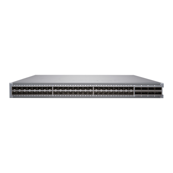
Two variants of the QFX5120 switches are available— 32-port and 48-port switches, with AC and DC power supplies and with different airflow directions. The QFX5120-48Y switch offers two models featuring AC power supplies with front-to-back or back-to-front airflow, and two models featuring DC power supplies with front-to-back or back-to-front airflow. - Page 21 Figure 2 on page 23 shows the rear view of the QFX5120-32C switch. Figure 2: QFX5120-32C - Rear View Figure 3 on page 23 shows the front view of the QFX5120-48Y switch. Figure 3: QFX5120-48Y - Front View Figure 4 on page 23 shows the front view of the QFX5120-48Y switch.
- Page 22 NOTE: The SFP-T transceivers are supported only on top or bottom ports, upto a maximum of 24 ports. The SFP28 speed can be applied only for individual quads (four ports). The speed cannot be configured for a single port. The native 25-G ports available from port 0 through port 47 and can operate in 1-G, 10-G, or 25-G speeds based on the configuration set at the quad level.
- Page 23 Figure 6 on page 25 shows the front panel of a QFX5120-48Y switch. Figure 6: Front Panel of a QFX5120-48Y Switch SFP ports QSFP ports — — Figure 8 on page 25 shows the rear panel of a QFX5120-32C switch with AC power supplies. Figure 7: Rear Panel of a QFX5120-32C Switch with AC Power Supplies AC power supply in slot 0, AC power supply in slot Fan modules...
- Page 24 Figure 9 on page 26 shows the rear view of a QFX5120-48Y switch with DC Power Supplies. Figure 9: Rear Panel of a QFX5120-48Y Switch with DC Power Supplies Figure 10 on page 26 shows the components on the rear panel of a QFX5120-48Y switch with DC Power Supplies.
-
Page 25: System Software
AIR IN (AFI) label. supplies (1+1 redundancy). System Software Juniper Networks QFX Series Ethernet Switches run Junos OS™ operating system (Junos OS), which provides Layer 2 and Layer 3 switching, routing, and security services. QFX5120 Power System QFX5120-48Y switches support two AC or DC power supplies with different airflow directions. Power supplies for the QFX5120 switch are fully redundant, load-sharing, and hot-removable and hot-insertable FRUs. -
Page 26: Qfx5120 Switch Models
CAUTION: Verify that the airflow direction on the power supply handle matches the direction of airflow in the chassis. Ensure that each power supply you install in the chassis has the same airflow direction. If you install power supplies with two different airflow directions, Junos OS raises an alarm. - Page 27 Table 4: QFX5120 Switch Models and Shipped Components (continued) Product Numbers Ports Power Supply Airflow QFX5120-48Y-AFO2 48 SFP28 Front-to-back—air intake to cool the chassis is 8 QSFP28 through the vents on the front panel of the chassis, and hot air exhausts through the vents on the rear panel of the chassis.
-
Page 28: Identifying Qfx5120 Switch Models
Identifying QFX5120 Switch Models Purpose Identify the model number of your QFX5120 switch. Action Check the value of the FRU Model Number field in the Routing Engine section in the output of the show chassis hardware extensive CLI command. user@switch> show chassis hardware extensive .. -
Page 29: Chassis Physical Specifications For Qfx5120 Switches
The labels on the fan modules and the power supplies indicate the direction of airflow they provide within the chassis when installed in the switch. AIR IN (AFI) labels indicate back-to-front airflow, and AIR OUT (AFO) labels indicate front-to-back airflow. The DC in the model number indicates that the switch model works on DC power supply. -
Page 30: Field-Replaceable Units In Qfx5120 Switches
NOTE: If you have a Juniper J-Care service contract, register any addition, change, or upgrade of hardware components at https://www.juniper.net/customers/support/tools/updateinstallbase/. Failure to do so can result in significant delays if you need replacement parts. This note does not apply if you replace existing components with the same type of component. - Page 31 QFX5120 Cooling System IN THIS SECTION QFX5120 Models with Front-to-Back Airflow | 33 QFX5120 Models with Back-to-Front Airflow | 34 Positioning the Switch | 36 QFX5120 Fan Module Status | 36 QFX5120 Models with Front-to-Back Airflow In the QFX5120 switch models that have front-to-back airflow, the air intake to cool the chassis is through the vents on the front panel of the switch, and hot air exhausts through the vents on the rear panel.
- Page 32 Figure 12: Front-to-Back Airflow Through QFX5120-48Y Switch Chassis Ports FRUs You must install only power supplies that have AIR OUT (AFO) labels in switches in which the fan modules have AIR OUT (AFO) labels. QFX5120 Models with Back-to-Front Airflow In the QFX5120 switch models that have back-to-front airflow, the air intake to cool the chassis is through the vents on the rear panel, and hot air exhausts through the vents on the front panel of the switch.
- Page 33 Figure 13: Back-to-Front Airflow Through a QFX5120-32C Switch Chassis Ports FRUs Figure 14 on page 35 shows the back-to-front airflow through the QFX5120-48Y switch chassis. Figure 14: Back-to-Front Airflow Through QFX5120-48Y Switch Chassis Ports FRUs You must install only power supplies that have AIR IN (AFI) labels in switches in which the fan modules have AIR IN (AFI) labels.
- Page 34 CAUTION: The system raises an alarm if a fan module fails or if the ambient temperature inside the chassis rises above the acceptable range. If the temperature inside the chassis rises above the threshold temperature, the system shuts down automatically. Positioning the Switch In a switch with front-to-back airflow, indicated by the label AIR OUT (AFO) on the fan modules and power supplies, hot air exhausts through the vents on the rear panel of the switch.
- Page 35 Management Port LEDs on QFX5120 Switches The two management port LEDs on the rear panel of a QFX5120 switch have two LEDs that indicate link activity and status of the management port. Figure 15 on page 37 shows the location of management port on QFX5120-32C.
- Page 36 Table 8: Link/Activity LED on the Management Port on QFX5120 Switches (continued) Color State and Description Status Green/Amber Indicates the speed. The speed indicators are: Off— Either the port speed is 10 M or the link is down. Amber— Link speed is 100 Mbps. Green—...
- Page 37 Figure 18: LEDs on the SFP+ Network Ports (QFX5120-32C) Status LED that denotes port 32 Status LED that denotes port 33 — — Figure 19 on page 39 shows the LEDs on the QSFP28 network ports on QFX5120-48Y. Figure 19: LEDs on the QSFP28 Network Ports (QFX5120-48Y) Network Port LEDs.
- Page 38 ports and the other three denote the channelized ports. See Table 9 on page 40 to know about the different link activity LEDs on QSFP28 Network ports. Table 9: Status LED on QSFP28 Ports Position Color State Description 1–4 Unlit The port is administratively disabled, there is no power, the link is down, or there is a fault.
-
Page 39: Qfx5120 Cooling System
Table 11: Status LED on SFP28 and SFP+ Uplink Ports Color State and Description Status Green Indicates the speed. The speed indicators are: Blinking green—1 Gbps and 10 Gbps Steadily green—25 Gbps QFX5120 Cooling System IN THIS SECTION QFX5120 Cooling System | 42 QFX5120 Models and Airflow Direction | 43 QFX5120 Models with Front-to-Back Airflow | 45 QFX5120 Models with Back-to-Front Airflow | 47... -
Page 40: Qfx5120 Cooling System
QFX5120 Cooling System QFX5120-48Y switches are shipped with five fan modules (4+1 redundancy) preinstalled at the rear of the chassis. QFX5120-32C switches are shipped with six fan modules (5+1 redundancy) preinstalled at the rear of the chassis. These fan modules are designed for one of the two available airflow directions (Airflow In or Airflow Out). - Page 41 Airflow in the Fan Model Number Power Supply Module Module Power Supplies QFX5120-32C-AFO The switch ships Juniper Gold Front-to-back—air For switches that with six fan intake to cool the have fan modules modules and two chassis is through with the AIR OUT...
- Page 42 Airflow in the Fan Model Number Power Supply Module Module Power Supplies QFX5120-32C-AFI The switch ships Juniper Azure Blue Back-to-front—air For switches that with six fan intake to cool the have fan modules modules and two chassis is through with the AIR IN...
- Page 43 AIR OUT label. the vents on the rear panel of the chassis. QFX5120-48Y-DC-AFI2 The switch ships Juniper Azure Blue Back-to-front—air For switches that with five fan intake to cool the have fan modules modules and two chassis is through...
- Page 44 Figure 11 on page 33 shows the front-to back airflow through the QFX5120-32C switch chassis. Figure 23: Front-to-Back Airflow Through QFX5120-32C Switch Chassis Ports FRUs Figure 12 on page 34 shows the front-to-back airflow through the QFX5120-48Y switch chassis. Figure 24: Front-to-Back Airflow Through QFX5120-48Y Switch Chassis Ports FRUs You must install only power supplies that have AIR OUT labels in switches in which the fan modules have...
-
Page 45: Qfx5120 Models With Back-To-Front Airflow
QFX5120 Models with Back-to-Front Airflow In the QFX5120 switch models that have back-to-front airflow, the air intake to cool the chassis is through the vents on the rear panel and hot air exhausts through the vents on the front panel of the switch. Figure 13 on page 35 shows the back-to-front airflow through QFX5120-32C switch chassis. -
Page 46: Positioning The Switch
Figure 26: Back-to-Front Airflow Through QFX5120-48Y Switch Chassis Ports FRUs You must install only power supplies that have AIR IN labels in switches in which the fan modules have AIR IN labels. Do not mix power supplies and fan modules with different airflow labels (AIR IN and AIR OUT) in the same chassis. -
Page 47: Qfx5120 Fan Module Status
In data center deployments, position the switch in such a manner that the AIR IN labels on switch components are next to the cold aisle, and AIR OUT labels on switch components are next to the hot aisle. QFX5120 Fan Module Status Each switch has a status LED for each fan module next to the fan module slot on the rear panel of the chassis. -
Page 48: Ac Power Supply In Qfx5120 Switches
QFX5120 DC Power Specifications | 60 DC Power Supply LEDs in QFX5120 Switches | 60 AC Power Supply in QFX5120 Switches IN THIS SECTION AC Power Supply Specifications for QFX5120 Switches | 50 AC Power Supply Airflow | 51 QFX5120 switches support two AC or DC power supplies with different airflow directions. Power supplies for the QFX5120 switch are fully redundant, load-sharing, and hot-removable and hot-insertable FRUs. -
Page 49: Ac Power Supply Airflow
Figure 28 on page 51 shows the AC power supply for a QFX5120-48Y switch. Figure 28: AC Power Supply for a QFX5120-48Y Switch AC Power Supply Airflow Each power supply is cooled by its own internal cooling system. The power supplies either have labels on the handles that indicate the direction of airflow or they have color-coded handles with a fan icon. -
Page 50: Ac Power Supply Specifications For Qfx5120 Switches
Juniper Gold JPSU-650W-AC-AI Back to front Juniper Azure Blue AC Power Supply Specifications for QFX5120 Switches QFX5120 switches support 650 W AC power supplies. The tables in this topic provides power supply specification of AC power supplies used in an QFX5120... -
Page 51: Ac Power Cord Specifications For Qfx5120 Switches
Table 15: Power Supply Specifications for QFX5120-32C Switches (continued) AC input line frequency 50–60 Hz AC input current rating 6A at 100 VAC 3.8A at 240 VAC Typical Power Consumption 380W Maximum power 515W Table 16 on page 53shows the power supply specifications for QFX5120-48Y switches. Table 16: Power Supply Specifications for QFX5120-48Y Switches Item Specification... - Page 52 AC power cord specifications for the countries and regions listed in the table. Table 17: AC Power Cord Specifications Country/Region Electrical Specifications Plug Standards Juniper Model Number Argentina 250 VAC, 10 A, 50 Hz IRAM 2073 Type RA/3 CBL-EX-PWR-C13-AR Australia...
-
Page 53: Ac Power Supply Leds In Qfx5120 Switches
Table 17: AC Power Cord Specifications (continued) Country/Region Electrical Specifications Plug Standards Juniper Model Number Taiwan 125 VAC, 11 A and 15 A, NEMA 5-15P Type N5-15P CBL-EX-PWR-C13-TW 50 Hz United Kingdom 250 VAC, 10 A, 50 Hz BS 1363/A Type BS89/13... - Page 54 Table 18: AC Power Supply LED on a QFX5120-32C Switch Color State Description Unlit The power supply is disconnected from power, or power is not coming into the power supply. Green On Steadily The power supply is sending out power correctly. Blinking The power supply is in standby mode.
-
Page 55: Dc Power Supply In Qfx5120 Switches
Table 19: AC Power Supply LEDs on QFX5120-48Y Switches Color State Description AC OK Unlit The power supply is disconnected from power, or power is not coming into the power supply. Green On steadily Power is coming into the power supply. DC OK Unlit The power supply is disconnected from... -
Page 56: Characteristics Of A Dc Power Supply
The DC power supply in QFX5120 switches is a hot-insertable and hot-removable field-replaceable unit (FRU): You can install it without powering off the switch or disrupting the switching function. All the QFX5120 switches that are powered by DC power supplies are shipped with one DC power supply pre-installed in the rear panel of the switches. -
Page 57: Dc Power Supply Airflow
Table 20: Details of the DC Power Supplies in QFX5120 Switches Details 650 W DC Power Supply Model number JPSU-650-DC-AFO JPSU-650-DC-AFI Field-replaceable unit (FRU) type Hot-insertable and hot-removable Power supply weight 2.43 lb (1.1 kg) Minimum installed in chassis Maximum installed in chassis Power supply slots Install in power supply slots labeled PSU 0 and PSU 1 in the rear panel of the chassis. -
Page 58: Qfx5120 Dc Power Specifications
Table 21: Airflow Direction in DC Power Supply Models for QFX5120 Switches Label on Power Model Supply Direction of Airflow JPSU-650-DC-AFO AIR OUT (AFO) Front-to-back—that is, air intake to cool the chassis is through the vents on the front panel of the chassis and hot air exhausts through the vents on the rear panel of the chassis. - Page 59 Figure 34: DC Power Supply Faceplate on a QFX5120-48Y Switch Input LED Fault LED — — Output LED — CAUTION: The V+ terminals are shunted internally together, as are the V- terminals. The same polarity terminal can be wired together from the same source to provide an additional current path in a higher power chassis.
- Page 60 Table 23: DC Power Supply LEDs on a QFX5120-48Y Switch (continued) Name Color State Description Fault Amber On steadily An error has been detected in the power supply. Replace the power supply as soon as possible. To maintain proper airflow through the chassis, leave the power supply installed in the chassis until you are ready to replace...
-
Page 61: Site Planning, Preparation, And Specifications
C HAPTER Site Planning, Preparation, and Specifications Site Preparation Checklist for QFX5120 Switches | 65 QFX5120 Site Guidelines and Requirements | 66 QFX5120 Network Cable and Transceiver Planning | 73 QFX5120 Management Cable Specifications and Pinouts | 81... -
Page 63: Site Preparation Checklist For Qfx5120 Switches
Site Preparation Checklist for QFX5120 Switches The checklist in Table 24 on page 65 summarizes the tasks you need to perform to prepare a site for installing a QFX5120 switch. Table 24: Site Preparation Checklist Item or Task For More Information Performed by Date Environment... -
Page 64: Qfx5120 Site Guidelines And Requirements
Table 24: Site Preparation Checklist (continued) Item or Task For More Information Performed by Date Cables Acquire cables and connectors: Determine the number of cables needed based on your planned configuration. Review the maximum distance allowed for each cable. Choose the length of the cable based on the distance between the hardware components being connected. - Page 65 Follow these environmental guidelines: The site must be as dust-free as possible, because dust can clog air intake vents and filters, reducing the efficiency of the switch cooling system. Maintain ambient airflow for normal switch operation. If the airflow is blocked or restricted, or if the intake air is too warm, the switch might overheat, leading to the switch temperature monitor shutting down the device to protect the hardware components.
-
Page 66: General Site Guidelines
General Site Guidelines Efficient device operation requires proper site planning and maintenance and proper layout of the equipment, rack or cabinet (if used), and wiring closet. To plan and create an acceptable operating environment for your device and prevent environmentally caused equipment failures: Keep the area around the chassis free from dust and conductive material, such as metal flakes. -
Page 67: Rack Requirements For Qfx5120 Switches
Table 26: Site Electrical Wiring Guidelines (continued) Site Wiring Factor Guidelines Radio frequency To reduce or eliminate RFI from your site wiring, do the following: interference Use a twisted-pair cable with a good distribution of grounding conductors. If you must exceed the recommended distances, use a high-quality twisted-pair cable with one ground conductor for each data signal when applicable. -
Page 68: Cabinet Requirements For Qfx5120 Switches
Table 27: Rack Requirements for the QFX5120 Switch (continued) Rack Requirement Guidelines Mounting bracket hole spacing The holes in the mounting brackets are spaced at 1 U (1.75 in. or 4.45 cm), so that the switch can be mounted in any rack that provides holes spaced at that distance. -
Page 69: Clearance Requirements For Airflow And Hardware Maintenance For Qfx5120 Switches
Table 28 on page 71 provides the cabinet requirements and specifications for the QFX5120 switch. Table 28: Cabinet Requirements for the QFX5120 Switch Cabinet Requirement Guidelines Cabinet size and clearance The minimum cabinet size for accommodating a QFX5120 switch is 36 in. (91.4 cm) deep. - Page 70 Leave at least 6 in. (15.2 cm) clearance on the left of the chassis for installing the grounding lug. Leave at least 24 in. (61 cm) clearance in front of and behind the switch for service personnel to remove and install hardware components. Figure 35: QFX5120-48Y Switch - Clearance Requirements for Airflow and Hardware Maintenance If you’re installing a QFX5120-32C Switch, note that the dimensions for the grounding lug are different (see...
-
Page 71: Qfx5120 Network Cable And Transceiver Planning
Figure 36: QFX5120-32C Switch - Clearance Requirements for Airflow and Hardware Maintenance 24.0 in. (61 cm) 20.29 in. (51.53 cm) 24.0 in. (61 cm) Clearance required Clearance required for maintenance for maintenance Ports FRUs 17.26 in. 17.26 Top view (44 cm) (44 cm) 21.59 in. -
Page 72: Sfp28 Direct Attach Copper Cables For Qfx5120 Switches
Juniper Networks with your Juniper Networks device. CAUTION: If you face a problem running a Juniper Networks device that uses a third-party optic or cable, the Juniper Networks Technical Assistance Center (JTAC) can help you diagnose the source of the problem. Your JTAC engineer might recommend that you check the third-party optic or cable and potentially replace it with an equivalent Juniper Networks optic or cable that is qualified for the device. -
Page 73: Cable Specifications
CAUTION: If you face a problem running a Juniper Networks device that uses a third-party optic or cable, the Juniper Networks Technical Assistance Center (JTAC) can help you diagnose the source of the problem. Your JTAC engineer might recommend that you check the third-party optic or cable and potentially replace it with an equivalent Juniper Networks optic or cable that is qualified for the device. -
Page 74: Qsfp28 Direct Attach Copper Cables For Qfx5120 Switches
Juniper Networks device. CAUTION: If you face a problem running a Juniper Networks device that uses a third-party optic or cable, the Juniper Networks Technical Assistance Center (JTAC) can help you diagnose the source of the problem. Your JTAC engineer might recommend that you check the third-party optic or cable and potentially replace it with an equivalent Juniper Networks optic or cable that is qualified for the device. -
Page 75: Cable Specifications For Qsfp+ And Qsfp28 Transceivers On Qfx5120 Switches
The 40-Gigabit Ethernet QSFP+ and 100-Gigabit Ethernet QSFP28 transceivers that are used in QFX5120 switches use 12-ribbon multimode fiber crossover cables with female MPO/UP, MPO/UPC, or MPO/APC connectors. The fiber can be either OM3 or OM4. These cables are not sold by Juniper Networks. CAUTION: To maintain agency approvals, use only a properly constructed, shielded cable. -
Page 76: Calculating The Fiber-Optic Cable Power Budget For Qfx Series Switches
Table 29: QSFP+ and QSFP28 MPO Cable Signals (continued) Fiber Signal Rx1 (Receive) Rx0 (Receive) Table 30 on page 78 shows the pin-to-pin connections for proper polarity Table 30: QSFP+ and QSFP28 MPO Fiber-Optic Crossover Cable Pinouts Calculating the Fiber-Optic Cable Power Budget for QFX Series Switches Calculate the fiber-optic data link's power budget when planning fiber-optic cable layout and distances to ensure that fiber-optic connections have sufficient power for correct operation. -
Page 77: Calculating The Fiber-Optic Cable Power Margin For Qfx Series Switches
worst-case analysis to provide a margin of error, even though all the parts of an actual system do not operate at the worst-case levels. To calculate the worst-case estimate for the fiber-optic cable power budget (P ) for the link: 1. - Page 78 To calculate the worst-case estimate for the power margin (P ) for the link: 1. Determine the maximum value for link loss (LL) by adding estimated values for applicable link-loss factors; for example, use the sample values for various factors as provided in Table 31 on page 80 (here, the link is 2 km long and multimode, and the power margin (P...
-
Page 79: Qfx5120 Management Cable Specifications And Pinouts
Console Port Connector Pinout Information The console port on a Juniper Networks device is an RS-232 serial interface that uses an RJ-45 connector to connect to a console management device. The default baud rate for the console port is 9600 baud. -
Page 80: Rj-45 Management Port Connector Pinout Information
No Connection RJ-45 Management Port Connector Pinout Information Table 33 on page 82 provides the pinout information for the RJ-45 connector for the management port on Juniper Networks devices. Table 33: RJ-45 Management Port Connector Pinout Information Signal Description TRP1+ Transmit/receive data pair 1 TRP1—... -
Page 81: Rj-45 To Db-9 Serial Port Adapter Pinout Information
Table 33: RJ-45 Management Port Connector Pinout Information (continued) Signal Description TRP4— Transmit/receive data pair 4 RJ-45 to DB-9 Serial Port Adapter Pinout Information The console port is an RS-232 serial interface that uses an RJ-45 connector to connect to a management device such as a PC or a laptop. - Page 82 Table 35: SFP Network Port Connector Pinout Information Signal Description VeeT Module transmitter ground TX_Fault Module transmitter fault TX_Disable Transmitter disabled 2-wire serial interface data line SCL- 2-wire serial interface clock MOD_ABS Module absent Rate select RX_LOS Receiver loss of signal indication VeeR Module receiver ground VeeR...
- Page 83 Table 36: SFP+ and SFP28 Network Port Connector Pinout Information Signal Description VeeT Module transmitter ground TX_Fault Module transmitter fault TX_Disable Transmitter disabled 2-wire serial interface data line SCL- 2-wire serial interface clock MOD_ABS Module absent Rate select 0, optionally controls SFP+ module receiver RX_LOS Receiver loss of signal indication Rate select 1, optionally controls SFP+ transmitter...
- Page 84 Table 37: QSFP+ and QSFP28 Network Port Connector Pinout Information Signal TX2n TX2p TX4n TX4p ModSelL LPMode_Reset VccRx RX3p RX3n RX1p RX1n RX2n...
- Page 85 Table 37: QSFP+ and QSFP28 Network Port Connector Pinout Information (continued) Signal RX2p RX4n RX4p ModPrsL IntL VccTx Vcc1 Reserved TX3p TX3n TX1p TX1n...
-
Page 86: Initial Installation And Configuration
C HAPTER Initial Installation and Configuration Unpacking and Mounting the QFX5120 Switch | 91 Connecting the QFX5120 to Power | 98 Connecting the QFX5120 to the Network | 106 Connecting the QFX5120 to External Devices | 110 Configuring Junos OS on the QFX5120 | 112... -
Page 88: Unpacking And Mounting The Qfx5120 Switch
Unpacking and Mounting the QFX5120 Switch IN THIS SECTION Unpacking the Switch | 91 Parts Inventory (Packing List) for a QFX5120 Switch | 92 Registering Products—Mandatory for Validating SLAs | 93 Mounting a QFX5120 Switch on Four Posts of a Rack or Cabinet | 93 Unpacking the Switch QFX5120 switches are shipped in a cardboard carton, secured with foam packing material. -
Page 89: Parts Inventory (Packing List) For A Qfx5120 Switch
The parts shipped depend on the switch model you order. If any part in the packing list is missing, contact your customer service representative or contact Juniper customer care from within the U.S. or Canada by telephone at 1-888-314-5822. For international-dial or direct-dial options in countries without toll-free numbers, see https://www.juniper.net/support/requesting-support.html... -
Page 90: Registering Products-Mandatory For Validating Slas
You must provide the appropriate mounting screws for mounting the switch on a rack or a cabinet. Registering Products—Mandatory for Validating SLAs Register all new Juniper Networks hardware products and changes to an existing installed product using the Juniper Networks website to activate your hardware replacement service-level agreements (SLAs). CAUTION:... - Page 91 NOTE: To ensure that the protective earthing terminal is accessible through the opening in the rear mounting bracket: Ensure that the rack is 27.5-in. (70-cm) through 30.5-in. (77.5-cm) deep if you are mounting the switch flush with the rack front on four posts of a rack. Ensure that the rack is 29.5-in.
- Page 92 To mount a QFX5120 switch on four posts of a rack: 1. Place the switch on a flat, stable surface. 2. Align the side mounting rails along the side panels of the switch chassis. Align the two holes in the rear of the side mounting rails with the two holes on the rear of the side panels.
- Page 93 Figure 41: Attaching the Side Mounting Rail to a QFX5120-32C Switch Chassis 5. One person should grasp both sides of the switch, lift the switch, and position it in the rack, aligning the holes of the side mounting rails with the threaded holes in the front post of the rack. Align the bottom hole in both the front mounting brackets with a hole in each rack rail, making sure that the chassis is level.
- Page 94 8. Attach the rear mounting brackets to the rear post by using the appropriate screws for your rack. Tighten the screws. See Figure 44 on page 97 Figure 45 on page 97 Figure 44: Connecting Rear Mounting Brackets to a QFX5120-48Y Switch Figure 45: Connecting Rear Mounting Brackets to a QFX5120-32C Switch 9.
-
Page 95: Connecting The Qfx5120 To Power
Connecting the QFX5120 to Power IN THIS SECTION Connecting Earth Ground to a QFX5120 Switch | 98 Connecting AC Power to a QFX5120 Switch | 99 Connecting DC Power to a QFX5120 Switch | 101 Connecting Earth Ground to a QFX5120 Switch To connect earth ground to a switch: 1. -
Page 96: Connecting Ac Power To A Qfx5120 Switch
Figure 47: Connecting a Grounding Cable to a QFX5120-32C Switch 3. Secure the grounding lug to the protective earthing terminal with the washers and screws. 4. Dress the grounding cable and ensure that it does not touch or block access to other switch components. WARNING: Ensure that the cable does not drape where people could trip over it. - Page 97 CAUTION: Before you connect power to the switch, a licensed electrician must attach a cable lug to the grounding and power cables that you supply. A cable with an incorrectly attached lug can damage the switch (for example, by causing a short circuit). To meet safety and electromagnetic interference (EMI) requirements and to ensure proper operation, you must connect the chassis to earth ground before you connect it to power.
-
Page 98: Connecting Dc Power To A Qfx5120 Switch
Figure 48: Connecting Power to an AC-Powered QFX5120-48Y Switch Figure 49: Connecting Power to an AC-Powered QFX5120-32C Switch 6. The switch powers on as soon as power is provided to the power supply. There is no power switch on the device. 7. - Page 99 and running. You can install replacement power supplies in the two slots next to the fan modules without powering off the switch or disrupting the switching function. WARNING: A DC-powered QFX5120-48Y is intended for installation only in a restricted access location. NOTE: The battery returns of the DC power supply must be connected as an isolated DC return (DC-I).
- Page 100 plant, you can use a multimeter to verify the resistance of the –48V and RTN DC cables to chassis ground: The cable with very low resistance (indicating a closed circuit) to chassis ground is positive (+) and will be installed on the V+ (return) DC power input terminal. The cable with very high resistance (indicating an open circuit) to chassis ground is negative (–) and will be installed on the V–...
- Page 101 source (A) to one power supply and connect source (B) to the second power supply. This configuration provides the commonly deployed A/B feed redundancy for the system. The terminal block of the power supply has four terminals labeled V+, V+, V–, and V– for connecting DC power source cables labeled positive (+) and negative (–).
- Page 102 Figure 50: DC Power Supply Faceplate of a QFX5120-48Y Switch Shunt negative input terminals (+RTN) ESD grounding point — — Shunt positive input terminals (-48V) Fault LED — — Terminal block Output LED — — Ejector lever Input LED — —...
-
Page 103: Connecting The Qfx5120 To The Network
Installing a Transceiver | 106 Connecting a Fiber-Optic Cable | 109 Installing a Transceiver The transceivers for Juniper Networks devices are hot-removable and hot-insertable field-replaceable units (FRUs). You can remove and replace them without powering off the device or disrupting the device functions. - Page 104 Juniper Networks with your Juniper Networks device. CAUTION: If you face a problem running a Juniper Networks device that uses a third-party optic or cable, the Juniper Networks Technical Assistance Center (JTAC) can help you diagnose the source of the problem. Your JTAC engineer might recommend that you check the third-party optic or cable and potentially replace it with an equivalent Juniper Networks optic or cable that is qualified for the device.
- Page 105 WARNING: Do not leave a fiber-optic transceiver uncovered except when inserting or removing a cable. The rubber safety cap keeps the port clean and prevents accidental exposure to laser light. 4. If the port in which you want to install the transceiver is covered with a dust cover, remove the dust cover and save it in case you need to cover the port later.
-
Page 106: Connecting A Fiber-Optic Cable
Connecting a Fiber-Optic Cable Before you begin to connect a fiber-optic cable to an optical transceiver installed in a device, ensure that you have taken the necessary precautions for safe handling of lasers (see “Laser and LED Safety Guidelines and Warnings” on page 178). -
Page 107: Connecting The Qfx5120 To External Devices
Connecting the QFX5120 to External Devices IN THIS SECTION Connecting a Device to a Network for Out-of-Band Management | 110 Connecting a Device to a Management Console by Using an RJ-45 Connector | 111 Connecting a Device to a Network for Out-of-Band Management You can monitor and manage these devices by using a dedicated management channel. - Page 108 Figure 55: Connecting a Device to a Network for Out-of-Band Management Connecting a Device to a Management Console by Using an RJ-45 Connector You can configure and manage these devices by using a dedicated management channel. Each device has a console port to which you can connect an Ethernet cable with an RJ-45 connector. Use the console port to connect the device to the console server or management console.
-
Page 109: Configuring Junos Os On The Qfx5120
NOTE: If your laptop or PC does not have a DB-9 male connector pin and you want to connect your laptop or PC directly to the device, use a combination of the RJ-45 to DB-9 female adapter supplied with the device and a USB to DB-9 male adapter. You must provide the USB to DB-9 male adapter. -
Page 110: Qfx5120 Default Configuration
QFX5120 Default Configuration Each QFX5120 switch is programmed with a factory default configuration that contains the values set for each configuration parameter when a switch is shipped. The default configuration file sets values for system parameters such as the system log and file messages. When you commit changes to the configuration, a new configuration file is created that becomes the active configuration. - Page 111 Stop Bits—1 DCD State—Disregard Also gather the following information: Name the switch will use on the network Domain name the switch will use IP address and prefix length information for the Ethernet interface IP address of a default switch IP address of a DNS server Password for the root user This procedure connects the switch to the network, but does not enable it to forward traffic.
- Page 112 [edit] root@# set system root-authentication encrypted-password encrypted-password [edit] root@# set system root-authentication ssh-dsa public-key [edit] root@# set system root-authentication ssh-rsa public-key 6. Configure the name of the switch. If the name includes spaces, enclose the name in double quotation marks (“ ”). [edit] root@# set system host-name host-name 7.
- Page 113 [edit] root@# set interfaces em0 unit 0 family inet address address/prefix-length 11. Configure the IP address of a backup router, which is used only while the routing protocol is not running. [edit] root@# set system backup-router address 12. Configure the IP address of a DNS server. [edit] root@# set system name-server address 13.
- Page 114 em0 { unit 0 { family inet { address address/prefix-length; 16. Commit the configuration to activate it on the switch. [edit] root@# commit 17. (Optional) Configure additional properties by adding the necessary configuration statements. Then commit the changes to activate them on the switch. [edit] root@switch# commit 18.
-
Page 115: Maintaining Components
C HAPTER Maintaining Components Maintaining the QFX5120 Cooling System | 121 Maintaining the QFX5120 Power System | 124 Maintaining Transceivers | 129 Maintaining Fiber-Optic Cables | 138... -
Page 117: Maintaining The Qfx5120 Cooling System
Maintaining the QFX5120 Cooling System IN THIS SECTION Removing a Fan Module from a QFX5120 Switch | 121 Installing a Fan Module in a QFX5120 Switch | 122 Removing a Fan Module from a QFX5120 Switch The fan module in QFX5120 switches is a hot-removable and hot-insertable field-replaceable unit (FRU) installed in the rear panel of the switch: You can remove and replace it without powering off the switch or disrupting switch functions. -
Page 118: Installing A Fan Module In A Qfx5120 Switch
5. Install the replacement fan. 6. Tighten the captive screws on the faceplate of the fan module by using your fingers. If you are unable to tighten the captive screws by using your fingers, use the screwdriver. Figure 59: Removing a Fan Module from a QFX5120 Switch NOTE: Both the fan modules must be installed and operational for optimal functioning of the switch. - Page 119 NOTE: The fan module slots are located between the Management ports and PSUs. NOTE: If you have a Juniper J-Care service contract, register any addition, change, or upgrade of hardware components at https://www.juniper.net/customers/support/tools/updateinstallbase/ Failure to do so can result in significant delays if you need replacement parts. This note does not apply if you replace existing components with the same type of component.
-
Page 120: Maintaining The Qfx5120 Power System
Figure 60: Installing a Fan Module in a QFX5120-48Y Switch Figure 61: Installing a Fan Module in the QFX5120-32C Switch Maintaining the QFX5120 Power System IN THIS SECTION Removing Power Supply from a QFX5120 Switch | 124 Connecting AC Power to a QFX5120 Switch | 126 Removing Power Supply from a QFX5120 Switch All QFX5120 switches are shipped from the factory with two power supplies. - Page 121 Before you remove a power supply from a QFX5120, ensure that you have taken the necessary precautions to prevent electrostatic discharge (ESD) damage (see “Prevention of Electrostatic Discharge Damage” on page 191). Ensure that you have the following parts and tools available to remove a power supply from a QFX5120: ESD grounding strap Antistatic bag or an antistatic mat Phillips (+) screwdriver, number 2 (not provided)
-
Page 122: Connecting Ac Power To A Qfx5120 Switch
5. Slide the ejector lever toward the handle until it stops. 6. Grasp the power supply handle and pull firmly to slide the power supply halfway out of the chassis. 7. Place one hand under the power supply to support it and slide it completely out of the chassis. Take care not to touch power supply components, pins, leads, or solder connections. - Page 123 Ensure that you have taken the necessary precautions to prevent electrostatic discharge (ESD) damage (see “Prevention of Electrostatic Discharge Damage” on page 191). Ensure that you have connected the switch chassis to earth ground. CAUTION: Before you connect power to the switch, a licensed electrician must attach a cable lug to the grounding and power cables that you supply.
- Page 124 Figure 64: Connecting Power to an AC-Powered QFX5120-48Y Switch Figure 65: Connecting Power to an AC-Powered QFX5120-32C Switch 6. The switch powers on as soon as power is provided to the power supply. There is no power switch on the device. 7.
-
Page 125: Maintaining Transceivers
Installing a Transceiver | 134 Installing a QSFP28 Transceiver | 136 Removing a Transceiver The transceivers for Juniper Networks devices are hot-removable and hot-insertable field-replaceable units (FRUs). You can remove and replace them without powering off the device or disrupting device functions. - Page 126 3. Label the cable connected to the transceiver so that you can reconnect it correctly. WARNING: Do not look directly into a fiber-optic transceiver or into the ends of fiber-optic cables. Fiber-optic transceivers and fiber-optic cables connected to transceivers emit laser light that can damage your eyes. WARNING: Do not leave a fiber-optic transceiver uncovered except when inserting or removing a cable.
- Page 127 5. To remove an SFP, SFP+, XFP, or a QSFP+ transceiver: a. By using your fingers, pull open the ejector lever on the transceiver to unlock the transceiver. CAUTION: Before removing the transceiver, make sure that you open the ejector lever completely until you hear it click.
-
Page 128: Removing A Qsfp28 Transceiver
8. Place the dust cover over the empty port or install the replacement transceiver. Removing a QSFP28 Transceiver The transceivers for Juniper Networks devices are hot-removable and hot-insertable field-replaceable units (FRUs). You can remove and replace them without powering off the device or disrupting the device functions. - Page 129 4. Disconnect the cable from the transceiver. Immediately cover the transceiver and the end of the cable with a rubber safety cap. CAUTION: Do not leave a fiber-optic transceiver uncovered except when inserting or removing a cable. The safety cap keeps the port clean and prevents accidental exposure to laser light.
-
Page 130: Installing A Transceiver
Juniper Networks with your Juniper Networks device. CAUTION: If you face a problem running a Juniper Networks device that uses a third-party optic or cable, the Juniper Networks Technical Assistance Center (JTAC) can help you diagnose the source of the problem. Your JTAC engineer might recommend that you check the third-party optic or cable and potentially replace it with an equivalent Juniper Networks optic or cable that is qualified for the device. - Page 131 3. Check to see whether the transceiver is covered with a rubber safety cap. If it is not, cover the transceiver with a rubber safety cap. WARNING: Do not leave a fiber-optic transceiver uncovered except when inserting or removing a cable. The rubber safety cap keeps the port clean and prevents accidental exposure to laser light.
-
Page 132: Installing A Qsfp28 Transceiver
Juniper Networks with your Juniper Networks device. CAUTION: If you face a problem running a Juniper Networks device that uses a third-party optic or cable, the Juniper Networks Technical Assistance Center (JTAC) can help you diagnose the source of the problem. Your JTAC engineer might recommend that you check the third-party optic or cable and potentially replace it with an equivalent Juniper Networks optic or cable that is qualified for the device. - Page 133 To install a QSFP28 transceiver (see Figure 69 on page 137): 1. Wrap and fasten one end of the ESD wrist strap around your bare wrist, and connect the other end of the strap to the ESD point on the switch. 2.
-
Page 134: Maintaining Fiber-Optic Cables
CAUTION: Do not let fiber-optic cable hang free from the connector. Do not allow fastened loops of cable to dangle, which stresses the cable at the fastening point. CAUTION: Avoid bending fiber-optic cable beyond its minimum bend radius. An arc smaller than a few inches in diameter can damage the cable and cause problems that are difficult to diagnose. -
Page 135: Disconnecting A Fiber-Optic Cable
Do not let fiber-optic cables hang free from the connector. Do not allow fastened loops of cables to dangle, which stresses the cables at the fastening point. Disconnecting a Fiber-Optic Cable Juniper Networks devices have field-replaceable unit (FRU) optical transceivers to which you can connect fiber-optic cables. -
Page 136: Maintaining Fiber-Optic Cables
The rubber safety cap keeps the port clean and prevents accidental exposure to laser light. 4. Cover the fiber-optic cable connector with the rubber safety cap. Maintaining Fiber-Optic Cables Fiber-optic cables connect to optical transceivers that are installed in Juniper Networks devices. To maintain fiber-optic cables:... - Page 137 When you unplug a fiber-optic cable from a transceiver, place rubber safety caps over the transceiver and on the end of the cable. Anchor fiber-optic cables to prevent stress on the connectors. When attaching a fiber-optic cable to a transceiver, be sure to secure the fiber-optic cable so that it does not support its own weight as it hangs to the floor.
-
Page 138: Troubleshooting Hardware
C HAPTER Troubleshooting Hardware Troubleshooting QFX5120 Components | 145... -
Page 140: Troubleshooting Qfx5120 Components
Troubleshooting QFX5120 Components IN THIS SECTION Understanding Alarms | 145 Interface Alarm Messages | 146 Creating an Emergency Boot Device | 147 Understanding Alarms The QFX series switches support different alarm types and severity levels. Table 39 on page 145 provides a list of alarm terms and definitions that may help you in monitoring the device. -
Page 141: Interface Alarm Messages
Table 39: Alarm Terms and Definitions (continued) Term Definition Alarm types Alarms include the following types: Chassis alarm—Predefined alarm triggered by a physical condition on the device such as a power supply failure or excessive component temperature. Interface alarm—Alarm you configure to alert you when an interface link is down. Applies to ethernet, fibre-channel, and management-ethernet interfaces. -
Page 142: Creating An Emergency Boot Device
In the following procedure, we assume that you are creating the emergency boot device on a switch. You can create the emergency boot device on another Juniper Networks switch or router, or any PC or laptop that supports Linux. The steps you take to create the emergency boot device vary, depending on the device. - Page 143 root@device% dd if=/var/tmp/install-media-host-usb-ex-4e-flex-x86-64-18.3R1.10-secure.img 11006+1 records in 11006+1 records out 180332544 bytes transferred in 71.764266 secs (2512846 bytes/sec) 6. Log out of the shell: root@device% exit % exit user@device>...
-
Page 144: Contacting Customer Support And Returning The Chassis Or Components
C HAPTER Contacting Customer Support and Returning the Chassis or Components Returning a QFX5120 Chassis or Components | 151... -
Page 146: Returning A Qfx5120 Chassis Or Components
Packing a QFX5120 Switch or Component for Shipping | 155 Returning a QFX5120 Switch or Component for Repair or Replacement If you need to return a switch or hardware component to Juniper Networks for repair or replacement, follow this procedure: 1. -
Page 147: Locating The Serial Number On A Qfx5120 Switch Or Component
Locating the Serial Number ID Labels on FRUs in a QFX5120 Switch | 153 If you are returning a switch or hardware component to Juniper Networks for repair or replacement, you must locate the serial number of the switch or component. You must provide the serial number to the Juniper Networks Technical Assistance Center (JTAC) when you contact them to obtain Return Materials Authorization (RMA). -
Page 148: Locating The Serial Number Id Labels On Frus In A Qfx5120 Switch
Figure 71: Location of the Chassis Serial Number ID Label on QFX5120-48Y Switches Chassis Serial Number — Locating the Serial Number ID Labels on FRUs in a QFX5120 Switch The power supplies and fan module installed in QFX5120 switches are field-replaceable units (FRUs). For each of these FRUs, you must remove the FRU from the switch chassis to see the FRU’s serial number ID label. -
Page 149: Contacting Customer Support To Obtain Return Material Authorization
Figure 74: Location of the Serial Number ID Label on the Fan Module Used in a QFX5120-48Y Switch Contacting Customer Support to Obtain Return Material Authorization If you are returning a device or hardware component to Juniper Networks for repair or replacement, obtain a Return Material Authorization (RMA) number from Juniper Networks Technical Assistance Center (JTAC). -
Page 150: Packing A Qfx5120 Switch Or Component For Shipping
Packing QFX5120 Switch Components for Shipping | 157 Packing a QFX5120 Switch for Shipping If you need to transport the switch to another location or return the switch to Juniper Networks, you need to pack the switch securely in its original packaging to prevent damage during transportation. - Page 151 1. On the console or other management device connected to the switch, enter the CLI operational mode and issue the following command to shut down the switch software: user@switch> request system halt Wait until a message appears on the console confirming that the operating system has halted. 2.
-
Page 152: Packing Qfx5120 Switch Components For Shipping
7. Place the top portion of the packaging foam on top of the switch. 8. If you are returning accessories or field-replaceable units (FRUs) with the switch, pack them as instructed “Packing QFX5120 Switch Components for Shipping” on page 157. 9. - Page 153 C HAPTER Safety and Compliance Information General Safety Guidelines and Warnings | 161 Definitions of Safety Warning Levels | 162 Qualified Personnel Warning | 164 Warning Statement for Norway and Sweden | 165 Fire Safety Requirements | 165 Installation Instructions Warning | 167 Chassis and Component Lifting Guidelines | 167 Restricted Access Warning | 169 Ramp Warning | 171...
- Page 154 Action to Take After an Electrical Accident | 191 Prevention of Electrostatic Discharge Damage | 191 AC Power Electrical Safety Guidelines | 193 AC Power Disconnection Warning | 194 DC Power Electrical Safety Guidelines | 195 DC Power Disconnection Warning | 196 DC Power Grounding Requirements and Warning | 198 DC Power Wiring Sequence Warning | 200 DC Power Wiring Terminations Warning | 203...
-
Page 155: General Safety Guidelines And Warnings
General Safety Guidelines and Warnings The following guidelines help ensure your safety and protect the device from damage. The list of guidelines might not address all potentially hazardous situations in your working environment, so be alert and exercise good judgment at all times. Perform only the procedures explicitly described in the hardware documentation for this device. -
Page 156: Definitions Of Safety Warning Levels
Always ensure that all modules, power supplies, and cover panels are fully inserted and that the installation screws are fully tightened. Definitions of Safety Warning Levels The documentation uses the following levels of safety warnings (there are two Warning formats): NOTE: You might find this information helpful in a particular situation, or you might overlook this important information if it was not highlighted in a Note. - Page 157 WARNING: This symbol means danger. You are in a situation that could cause bodily injury. Before you work on any equipment, be aware of the hazards involved with electrical circuitry and be familiar with standard practices for preventing accidents. Waarschuwing Dit waarschuwingssymbool betekent gevaar. U verkeert in een situatie die lichamelijk letsel kan veroorzaken.
-
Page 158: Qualified Personnel Warning
Varning! Denna varningssymbol signalerar fara. Du befinner dig i en situation som kan leda till personskada. Innan du utför arbete på någon utrustning måste du vara medveten om farorna med elkretsar och känna till vanligt förfarande för att förebygga skador. Qualified Personnel Warning WARNING: Only trained and qualified personnel should install or replace the device. -
Page 159: Warning Statement For Norway And Sweden
In addition, you should establish procedures to protect your equipment in the event of a fire emergency. Juniper Networks products should be installed in an environment suitable for electronic equipment. We recommend that fire suppression equipment be available in the event of a fire in the vicinity of the equipment and that all local fire, safety, and electrical codes and ordinances be observed when you install and operate your equipment. - Page 160 To keep warranties effective, do not use a dry chemical fire extinguisher to control a fire at or near a Juniper Networks device. If a dry chemical fire extinguisher is used, the unit is no longer eligible for coverage under a service agreement.
-
Page 161: Installation Instructions Warning
Installation Instructions Warning WARNING: Read the installation instructions before you connect the device to a power source. Waarschuwing Raadpleeg de installatie-aanwijzingen voordat u het systeem met de voeding verbindt. Varoitus Lue asennusohjeet ennen järjestelmän yhdistämistä virtalähteeseen. Attention Avant de brancher le système sur la source d'alimentation, consulter les directives d'installation. - Page 162 Up to 39.7 lb (18 kg): One person. 39.7 lb (18 kg) to 70.5 lb (32 kg): Two or more people. 70.5 lb (32 kg) to 121.2 lb (55 kg): Three or more people. Above 121.2 lbs (55 kg): Material handling systems (such as levers, slings, lifts and so on) must be used. When this is not practical, specially trained persons or systems must be used (riggers or movers).
-
Page 163: Restricted Access Warning
Restricted Access Warning... - Page 164 WARNING: This unit is intended for installation in restricted access areas. A restricted access area is an area to which access can be gained only by service personnel through the use of a special tool, lock and key, or other means of security, and which is controlled by the authority responsible for the location.
-
Page 165: Ramp Warning
de servicio mediante la utilización de una herramienta especial, cerradura con llave, o algún otro medio de seguridad, y que está bajo el control de la autoridad responsable del local. Varning! Denna enhet är avsedd för installation i områden med begränsat tillträde. Ett område med begränsat tillträde får endast tillträdas av servicepersonal med ett speciellt verktyg, lås och nyckel, eller annan säkerhetsanordning, och kontrolleras av den auktoritet som ansvarar för området. - Page 166 De onderstaande richtlijnen worden verstrekt om uw veiligheid te verzekeren: De Juniper Networks switch moet in een stellage worden geïnstalleerd die aan een bouwsel is verankerd. Dit toestel dient onderaan in het rek gemonteerd te worden als het toestel het enige in het rek is.
- Page 167 Les directives ci-dessous sont destinées à assurer la protection du personnel: Le rack sur lequel est monté le Juniper Networks switch doit être fixé à la structure du bâtiment. Si cette unité constitue la seule unité montée en casier, elle doit être placée dans le bas.
- Page 168 Para garantizar su seguridad, proceda según las siguientes instrucciones: El Juniper Networks switch debe instalarse en un bastidor fijado a la estructura del edificio. Colocar el equipo en la parte inferior del bastidor, cuando sea la única unidad en el mismo.
- Page 169 Följande riktlinjer ges för att trygga din säkerhet: Juniper Networks switch måste installeras i en ställning som är förankrad i byggnadens struktur.
-
Page 170: Grounded Equipment Warning
Grounded Equipment Warning WARNING: The device is intended to be grounded. During normal use, ensure that you have connected earth ground to the chassis. Waarschuwing Deze apparatuur hoort geaard te worden Zorg dat de host-computer tijdens normaal gebruik met aarde is verbonden. Varoitus Tämä... -
Page 171: Radiation From Open Port Apertures Warning
Radiation from Open Port Apertures Warning WARNING: Because invisible radiation might be emitted from the aperture of the port when no fiber cable is connected, avoid exposure to radiation and do not stare into open apertures. Waarschuwing Aangezien onzichtbare straling vanuit de opening van de poort kan komen als er geen fiberkabel aangesloten is, dient blootstelling aan straling en het kijken in open openingen vermeden te worden. -
Page 172: Laser And Led Safety Guidelines And Warnings
Class 1 LED Product Warning | 180 Laser Beam Warning | 181 Juniper Networks devices are equipped with laser transmitters, which are considered a Class 1 Laser Product by the U.S. Food and Drug Administration and are evaluated as a Class 1 Laser Product per EN 60825-1 requirements. -
Page 173: Class 1 Laser Product Warning
Class 1 Laser Product Warning WARNING: Class 1 laser product. Waarschuwing Klasse-1 laser produkt. Varoitus Luokan 1 lasertuote. Attention Produit laser de classe I. Warnung Laserprodukt der Klasse 1. Avvertenza Prodotto laser di Classe 1. Advarsel Laserprodukt av klasse 1. Aviso Produto laser de classe 1. -
Page 174: Class 1 Led Product Warning
Class 1 LED Product Warning WARNING: Class 1 LED product. Waarschuwing Klasse 1 LED-product. Varoitus Luokan 1 valodiodituote. Attention Alarme de produit LED Class I. Warnung Class 1 LED-Produktwarnung. Avvertenza Avvertenza prodotto LED di Classe 1. Advarsel LED-produkt i klasse 1. Aviso Produto de classe 1 com LED. -
Page 175: Laser Beam Warning
Laser Beam Warning WARNING: Do not stare into the laser beam or view it directly with optical instruments. Waarschuwing Niet in de straal staren of hem rechtstreeks bekijken met optische instrumenten. Varoitus Älä katso säteeseen äläkä tarkastele sitä suoraan optisen laitteen avulla. Attention Ne pas fixer le faisceau des yeux, ni l'observer directement à... - Page 176 Operating Temperature Warning | 187 Product Disposal Warning | 189 While performing the maintenance activities for devices, observe the following guidelines and warnings:...
-
Page 177: Battery Handling Warning
Battery Handling Warning WARNING: Replacing a battery incorrectly might result in an explosion. Replace a battery only with the same or equivalent type recommended by the manufacturer. Dispose of used batteries according to the manufacturer's instructions. Waarschuwing Er is ontploffingsgevaar als de batterij verkeerd vervangen wordt. Vervang de batterij slechts met hetzelfde of een equivalent type dat door de fabrikant aanbevolen is. -
Page 178: Jewelry Removal Warning
Jewelry Removal Warning... - Page 179 WARNING: Before working on equipment that is connected to power lines, remove jewelry, including rings, necklaces, and watches. Metal objects heat up when connected to power and ground and can cause serious burns or can be welded to the terminals. Waarschuwing Alvorens aan apparatuur te werken die met elektrische leidingen is verbonden, sieraden (inclusief ringen, kettingen en horloges) verwijderen.
-
Page 180: Lightning Activity Warning
Varning! Tag av alla smycken (inklusive ringar, halsband och armbandsur) innan du arbetar på utrustning som är kopplad till kraftledningar. Metallobjekt hettas upp när de kopplas ihop med ström och jord och kan förorsaka allvarliga brännskador; metallobjekt kan också sammansvetsas med kontakterna. Lightning Activity Warning WARNING: Do not work on the system or connect or disconnect cables during periods... -
Page 181: Operating Temperature Warning
Operating Temperature Warning... - Page 182 6 in. (15.2 cm) of clearance around the ventilation openings. Waarschuwing Om te voorkomen dat welke switch van de Juniper Networks router dan ook oververhit raakt, dient u deze niet te bedienen op een plaats waar de maximale aanbevolen omgevingstemperatuur van 40°...
-
Page 183: Product Disposal Warning
Varning! Förhindra att en Juniper Networks switch överhettas genom att inte använda den i ett område där den maximalt rekommenderade omgivningstemperaturen på 40° C överskrids. Förhindra att luftcirkulationen inskränks genom att se till att det finns fritt utrymme på minst 15,2 cm omkring ventilationsöppningarna. -
Page 184: General Electrical Safety Guidelines And Warnings
General Electrical Safety Guidelines and Warnings WARNING: Certain ports on the device are designed for use as intrabuilding (within-the-building) interfaces only (Type 2 or Type 4 ports as described in GR-1089-CORE) and require isolation from the exposed outside plant (OSP) cabling. To comply with NEBS requirements and protect against lightning surges and commercial power disturbances, the intrabuilding ports must not be metallically connected to interfaces that connect to the OSP or its wiring. -
Page 185: Action To Take After An Electrical Accident
Operate the device within marked electrical ratings and product usage instructions. To ensure that the device and peripheral equipment function safely and correctly, use the cables and connectors specified for the attached peripheral equipment, and make certain they are in good condition. You can remove and replace many device components without powering off or disconnecting power to the device, as detailed elsewhere in the hardware documentation for this device. - Page 186 Always use an ESD wrist strap when you are handling components that are subject to ESD damage, and make sure that it is in direct contact with your skin. If a grounding strap is not available, hold the component in its antistatic bag (see Figure 75 on page 192) in one hand and touch the exposed, bare metal of the device with the other hand immediately before...
-
Page 187: Ac Power Electrical Safety Guidelines
AC Power Electrical Safety Guidelines CAUTION: For devices with AC power supplies, an external surge protective device (SPD) must be used at the AC power source. The following electrical safety guidelines apply to AC-powered devices: Note the following warnings printed on the device: “CAUTION: THIS UNIT HAS MORE THAN ONE POWER SUPPLY CORD. -
Page 188: Ac Power Disconnection Warning
AC Power Disconnection Warning WARNING: Before working on the device or near power supplies, unplug all the power cords from an AC-powered device. Waarschuwing Voordat u aan een frame of in de nabijheid van voedingen werkt, dient u bij wisselstroom toestellen de stekker van het netsnoer uit het stopcontact te halen. Varoitus Kytke irti vaihtovirtalaitteiden virtajohto, ennen kuin teet mitään asennuspohjalle tai työskentelet virtalähteiden läheisyydessä. -
Page 189: Dc Power Electrical Safety Guidelines
DC Power Electrical Safety Guidelines A DC-powered device is equipped with a DC terminal block that is rated for the power requirements of a maximally configured device. Incorporate an easily accessible disconnect device into the facility wiring. Be sure to connect the ground wire or conduit to a solid office earth ground. -
Page 190: Dc Power Disconnection Warning
DC Power Disconnection Warning... - Page 191 WARNING: Before performing any of the DC power procedures, ensure that power is removed from the DC circuit. To ensure that all power is off, locate the circuit breaker on the panel board that services the DC circuit, switch the circuit breaker to the OFF position, and tape the device handle of the circuit breaker in the OFF position.
-
Page 192: Dc Power Grounding Requirements And Warning
corrente contínua e coloque-o na posição OFF (Desligado), segurando nessa posição a manivela do interruptor do disjuntor com fita isoladora. ¡Atención! Antes de proceder con los siguientes pasos, comprobar que la alimentación del circuito de corriente continua (CC) esté cortada (OFF). Para asegurarse de que toda la alimentación esté... - Page 193 WARNING: When you install the device, the ground connection must always be made first and disconnected last. Waarschuwing Bij de installatie van het toestel moet de aardverbinding altijd het eerste worden gemaakt en het laatste worden losgemaakt. Varoitus Laitetta asennettaessa on maahan yhdistäminen aina tehtävä ensiksi ja maadoituksen irti kytkeminen viimeiseksi.
-
Page 194: Dc Power Wiring Sequence Warning
DC Power Wiring Sequence Warning... - Page 195 WARNING: Wire the DC power supply using the appropriate lugs. When connecting power, the proper wiring sequence is ground to ground, +RTN to +RTN, then –48 V to –48 V. When disconnecting power, the proper wiring sequence is –48 V to –48 V, +RTN to +RTN, then ground to ground.
- Page 196 último. Observe que el alambre de tierra se debe conectar siempre primero y desconectar por último. ¡Atención! Wire a fonte de alimentação de DC Usando os talões apropriados na extremidade da fiação. Ao conectar a potência, a seqüência apropriada da fiação é moída para moer, +RTN a +RTN, então –48 V a –48 V.
-
Page 197: Dc Power Wiring Terminations Warning
DC Power Wiring Terminations Warning... - Page 198 WARNING: When stranded wiring is required, use approved wiring terminations, such as closed-loop or spade-type with upturned lugs. These terminations must be the appropriate size for the wires and must clamp both the insulation and conductor. Waarschuwing Wanneer geslagen bedrading vereist is, dient u bedrading te gebruiken die voorzien is van goedgekeurde aansluitingspunten, zoals het gesloten-lus type of het grijperschop type waarbij de aansluitpunten omhoog wijzen.
- Page 199 hacia arriba. Estos terminales deberán ser del tamaño apropiado para los cables que se utilicen, y tendrán que sujetar tanto el aislante como el conductor. Varning! När flertrådiga ledningar krävs måste godkända ledningskontakter användas, t.ex. kabelsko av sluten eller öppen typ med uppåtvänd tapp. Storleken på dessa kontakter måste vara avpassad till ledningarna och måste kunna hålla både isoleringen och ledaren fastklämda.
-
Page 200: Multiple Power Supplies Disconnection Warning
Multiple Power Supplies Disconnection Warning WARNING: The network device has more than one power supply connection. All connections must be removed completely to remove power from the unit completely. Waarschuwing Deze eenheid heeft meer dan één stroomtoevoerverbinding; alle verbindingen moeten volledig worden verwijderd om de stroom van deze eenheid volledig te verwijderen. -
Page 201: Tn Power Warning
TN Power Warning WARNING: The device is designed to work with a TN power system. Waarschuwing Het apparaat is ontworpen om te functioneren met TN energiesystemen. Varoitus Koje on suunniteltu toimimaan TN-sähkövoimajärjestelmien yhteydessä. Attention Ce dispositif a été conçu pour fonctionner avec des systèmes d'alimentation Warnung Das Gerät ist für die Verwendung mit TN-Stromsystemen ausgelegt. - Page 202 BSMI CNS 13438 Taiwan Radiated and Conducted Emissions (at 10 Meter) KN 32 and KN 35 Korea Radiated Emission and Immunity Characteristics (at 10 Meter) KN 61000 Korea Immunity Test IEC/EN 61000 Immunity Test TEC/SD/DD/EMC-221/05/OCT-16 (Supersedes No. TEC/EMI/TEL-001/01/FEB-09) India EMC standard Juniper Inductive GND (JIG)
-
Page 203: Compliance Statements For Emc Requirements For The Qfx Series
Compliance Statements for EMC Requirements for the QFX Series IN THIS SECTION QFX 5120 | 209 Canada | 210 European Community | 211 Israel | 211 Japan | 211 Korea | 212 Tawain | 212 United States | 212 Nonregulatory Environmental Standards | 213 This topic describes the EMC requirements for the QFX Series. -
Page 204: Canada
KN 32 and KN 35 Korea Radiated Emission and Immunity Characteristics (at 10 Meter) KN 61000 Korea Immunity Test TEC/SD/DD/EMC-221/05/OCT-16 (Supersedes No. TEC/EMI/TEL-001/01/FEB-09) India EMC standard Juniper Inductive GND (JIG) Canada This Class A digital apparatus complies with Canadian ICES-003. -
Page 205: European Community
European Community This is a Class A product. In a domestic environment this product may cause radio interference in which case the user may be required to take adequate measures. Israel Translation from Hebrew–Warning: This product is Class A. In residential environments, the product may cause radio interference, and in such a situation, the user may be required to take adequate measures. -
Page 206: Korea
Korea Korean Class A Warning The preceding translates as follows: This equipment is Industrial (Class A) electromagnetic wave suitability equipment and seller or user should take notice of it, and this equipment is to be used in the places except for home. Tawain Chinese Class A warning The preceding translates as follows:... -
Page 207: Nonregulatory Environmental Standards
Nonregulatory Environmental Standards These QFX Series product SKUs are designed to be Network Equipment Building System (NEBS) compliant: QFX3008-I QFX3600-I QFX3600 QFX3500 QFX5100 QFX5110 QFX5200-32C QFX10002-36Q and QFX10002-72Q QFX10008 QFX10016 Those device product SKUs are designed to meet the following NEBS compliance standards: SR-3580 NEBS Criteria Levels (Level 3 Compliance) GR-1089-CORE, Issue 6: EMC and Electrical Safety—Generic Criteria for Network Telecommunications Equipment...
Need help?
Do you have a question about the QFX5120 Series and is the answer not in the manual?
Questions and answers