
Related Manuals for Juniper QFX Series


Summary of Contents for Juniper QFX Series
- Page 1 QFX5110 Switch Hardware Guide Modified: 2019-04-02 Copyright © 2019, Juniper Networks, Inc.
- Page 2 END USER LICENSE AGREEMENT The Juniper Networks product that is the subject of this technical documentation consists of (or is intended for use with) Juniper Networks software. Use of such software is subject to the terms and conditions of the End User License Agreement (“EULA”) posted at https://support.juniper.net/support/eula/.
-
Page 3: Table Of Contents
QFX5110 Chassis Status LEDs ........37 Copyright © 2019, Juniper Networks, Inc. - Page 4 RJ-45 Management Port Connector Pinout Information ....76 Console Port Connector Pinouts for the QFX Series ....76...
- Page 5 QFX5110 Troubleshooting Resources Overview ..... . . 125 QFX Series Alarm Messages Overview ......126 Chassis Alarm Messages .
- Page 6 Radiation from Open Port Apertures Warning ......149 Laser and LED Safety Guidelines and Warnings for the QFX Series ... 149 Class 1M Laser Product Warning .
- Page 7 QFX5110 Agency Approvals ......... . 168 Agency Approvals for the QFX Series ....... 168 Compliance Statements for EMC Requirements for the QFX Series .
- Page 8 QFX5110 Switch Hardware Guide viii Copyright © 2019, Juniper Networks, Inc.
- Page 9 Figure 31: QFX5110 Virtual Chassis with all QFX5110 Members ....102 Figure 32: QFX5110 Virtual Chassis with QFX5110 and QFX5100 Members ..102 Copyright © 2019, Juniper Networks, Inc.
- Page 10 Safety and Compliance Information ....... . 137 Figure 46: Placing a Component into an Antistatic Bag ....159 Copyright © 2019, Juniper Networks, Inc.
- Page 11 Table 31: RJ-45 Management Port Connector Pinout Information ... . . 76 Table 32: Console Port Connector Pinouts for the QFX Series ....77...
- Page 12 Table 39: Chassis Alarm Messages ........127 Copyright © 2019, Juniper Networks, Inc.
-
Page 13: About The Documentation
® To obtain the most current version of all Juniper Networks technical documentation, see the product documentation page on the Juniper Networks website at https://www.juniper.net/documentation/ If the information in the latest release notes differs from the information in the documentation, follow the product Release Notes. -
Page 14: Merging A Full Example
For example, copy the following snippet to a file and name the file . Copy the file to the directory ex-script-snippet.conf ex-script-snippet.conf /var/tmp on your routing platform. commit { file ex-script-snippet.xsl; } Copyright © 2019, Juniper Networks, Inc. -
Page 15: Documentation Conventions
Alerts you to the risk of personal injury from a laser. Indicates helpful information. Best practice Alerts you to a recommended use or implementation. Table 2 on page xvi defines the text and syntax conventions used in this guide. Copyright © 2019, Juniper Networks, Inc. -
Page 16: Table 2: Text And Syntax Conventions
Indention and braces ( { } ) Identifies a level in the configuration [edit] hierarchy. routing-options { static { route default { ; (semicolon) Identifies a leaf statement at a nexthop address; configuration hierarchy level. retain; GUI Conventions Copyright © 2019, Juniper Networks, Inc. -
Page 17: Documentation Feedback
Requesting Technical Support Technical product support is available through the Juniper Networks Technical Assistance Center (JTAC). If you are a customer with an active Juniper Care or Partner Support Services support contract, or are covered under warranty, and need post-sales technical support, you can access our tools and resources online or open a case with JTAC. -
Page 18: Self-Help Online Tools And Resources
QFX5110 Switch Hardware Guide Self-Help Online Tools and Resources For quick and easy problem resolution, Juniper Networks has designed an online self-service portal called the Customer Support Center (CSC) that provides you with the following features: Find CSC offerings: https://www.juniper.net/customers/support/ Search for known bugs: https://prsearch.juniper.net/... -
Page 19: Overview
QFX5110 Field-Replaceable Units on page 25 QFX5110 Hardware Overview The QFX5110 line of switches is Juniper Network’s versatile fixed-chassis solution for hybrid cloud deployments. The small form-factor data center switches are designed for either core or aggregation environments with high performance and low latency. -
Page 20: Qfx5110 Models Overview
For a QFX5100 switch to participate in a QFX5110 Virtual Chassis, the switch must have the same software version and image installed as the software running on the QFX5110 switches in the Virtual Chassis. You do not need to configure mixed mode. In a QFX5110 Copyright © 2019, Juniper Networks, Inc. -
Page 21: Overview
Virtual Chassis, we recommend to use QFX5110 switches in the master and backup Routing Engine roles, and QFX5100 switches only in the line card role. A leaf device in a QFX5110 VCF (Junos OS Release 17.3R1 and later). Copyright © 2019, Juniper Networks, Inc. -
Page 22: Qfx5110-48S Hardware
(QSFP+) or 20 ports of QSFP+ and 4 ports of high-density 100-Gigabit Ethernet quad small form-factor pluggable solution (QSFP28). Each QSFP+ port can operate as a native 40-Gigabit Ethernet port, or as four independent 10-Gigabit Ethernet ports when Copyright © 2019, Juniper Networks, Inc. -
Page 23: System Software
Figure 2: QFX5110-32Q Port Panel System Software QFX Series devices use the Junos operating system (OS), which is installed on a QFX5110 switch’s 64-GB internal solid-state flash drive. The same Junos OS code base that runs on QFX5110 switches also runs on all Juniper Networks EX Series switches, and M Series, MX Series, and T Series routers. -
Page 24: Qfx5110 Hardware Models
4 QSFP28 QFX5110-32Q-AFO 32 QSFP+ Air Out (ports-to-FRUs) 4 QSFP28 QFX5110-32Q-AFI 32 QSFP+ Air In (FRUs-to-ports) 4 QSFP28 QFX5110-32Q-DC-AFO 32 QSFP+ Air Out (ports-to-FRUs) 4 QSFP28 QFX5110-32Q-DC-AFI 32 QSFP+ Air In (FRUs-to-ports) 4 QSFP28 Copyright © 2019, Juniper Networks, Inc. -
Page 25: Understanding Hardware Redundancy Of Qfx5110 Components And Functionality
CAUTION: Replace a failed power supply with a blank panel or new power supply within one minute of removal to prevent chassis overheating. The Copyright © 2019, Juniper Networks, Inc. -
Page 26: Qfx5110 Port Panels
“Removing a Transceiver” on page 113. NOTE: If you have a Juniper Care service contract, you can register any addition, change, or upgrade of hardware components at . Failure https://www.juniper.net/customers/support/tools/updateinstallbase/ to do so can result in significant delays if you need replacement parts. This note does not apply if you replace existing components with the same type of component. -
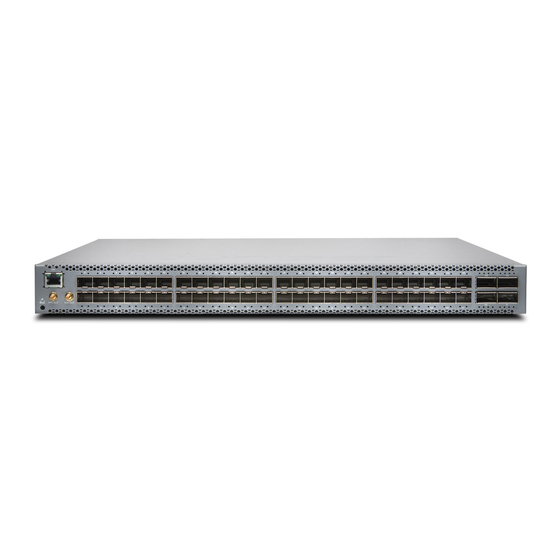
Page 27: Qfx5110-48S Port Panel
Figure 3: QFX5110-48S Port Panel 1— Electrostatic discharge (ESD) terminal 4— 4 QSFP28 ports 2— RJ-45 connection to grandmaster clock 5— Output clock at 10 Mhz 3— 48 SFP+ ports 6— 1 pulse per second (PPS) output connection Copyright © 2019, Juniper Networks, Inc. -
Page 28: Network Ports
To connect QFX5110 switches as members in a QFX5110 Virtual Chassis, you need a pair of dedicated ports on each switch and cables that link each member in the Virtual Chassis into a ring topology. Each member in the ring has at least one direct Virtual Chassis port Copyright © 2019, Juniper Networks, Inc. -
Page 29: Qfx5110-32Q Port Panel
(VCP) connection to a upstream and downstream member. QFX5110 switches are recommended in the master, backup, or line card role. You may only mix QFX5100 members with QFX5110 members in a QFX5110 Virtual Chassis; no other QFX Series or EX Series switches are supported. See “Connecting QFX5110 and QFX5100 Members in... -
Page 30: Network Ports
System mode–Flexi-pic mode is replaced by non-oversubscribed mode. The Flexible PIC Concentrator (FPC) no longer reboots when the system mode changes. Auto-sense–-The ports auto-sense the transceiver and set the port speed to match. Copyright © 2019, Juniper Networks, Inc. -
Page 31: Table 5: Default Behavior Of 100 Gigabit Ethernet Ports
Because there can be a slight loss of data while the FPC reboots, we recommend that you only configure the changes during a maintenance window for this release. Copyright © 2019, Juniper Networks, Inc. -
Page 32: Virtual Chassis And Virtual Chassis Fabric
(VCP) connection to a upstream and downstream member. QFX5110 switches are recommended in the master, backup, or line card role. You may only mix QFX5100 members with QFX5110 members in a QFX5110 Virtual Chassis; no other QFX Series or EX Series switches are supported. See “Connecting QFX5110 and QFX5100 Members in... -
Page 33: Table 6: Qfx5110-48 Access Port And Uplink Led Locations
Table 8: Network Port LEDs on QSFP28 Ports on a QFX5110 Position Color State Description 1–4 Unlit The port is administratively disabled, there is no power, the link is down, or there is a fault. Copyright © 2019, Juniper Networks, Inc. -
Page 34: Qfx5110 Management Panel
The management panel of the QFX5110 is found on the field-replaceable unit (FRU) end of the switch, as shown in Figure 5 on page 35. See Figure 6 on page 35 for FRUs and management panel detail. Copyright © 2019, Juniper Networks, Inc. -
Page 35: Figure 5: Qfx5110 Switch, Fru End
Ethernet (VME) interface for spine members in a VCF. See “Connecting a Device to a Network for Out-of-Band Management” on page NOTE: If both C0 ports are cabled, the copper C0 has priority over the fiber C0. C1–Use the SFP connector for 1000BASE-X. Copyright © 2019, Juniper Networks, Inc. -
Page 36: Qfx5110 Management Port Leds
A link is established, and there is link activity. Status Unlit Either the port speed is 10 M or the link is down. Green On steadily The port speed is 1000 M. Amber On steadily The port speed is 100 M. Copyright © 2019, Juniper Networks, Inc. -
Page 37: Qfx5110 Chassis Status Leds
LEDs on a QFX5110, their colors and states, and the status they indicate. You can view the colors of the three LEDs remotely through the CLI by issuing the operational mode command show chassis lcd Copyright © 2019, Juniper Networks, Inc. -
Page 38: Table 10: Chassis Status Leds On A Qfx5110 Switch
Junos OS boots properly. SYS–System Unlit The switch is powered off or halted. Green On steadily Junos OS for QFX Series is loaded on the switch. Green Blinking The switch is participating as: A member in a QFX Virtual Chassis... -
Page 39: Qfx5110 Cooling System
Related QFX5110 Field-Replaceable Units on page 25 Documentation USB Port Specifications for the QFX Series on page 83 QFX5110 Cooling System QFX5110 Cooling System and Airflow Description on page 39 QFX5110 Fan Module LED on page 44... -
Page 40: Fan Modules
Table 11 on page 41 lists the available fan module product SKUs and the direction of airflow in them. Copyright © 2019, Juniper Networks, Inc. -
Page 41: Table 11: Fan Modules In The Qfx5110
AIR IN on switch components are next to the cold aisle, and labels on switch AIR OUT components are next to the hot aisle. See Figure 10 on page 42 through Figure 13 on page Copyright © 2019, Juniper Networks, Inc. -
Page 42: Figure 10: Air In Airflow Through The Qfx5110-48S
QFX5110 Switch Hardware Guide Figure 10: Air In Airflow Through the QFX5110-48S Figure 11: Air Out Airflow Through the QFX5110-48S Copyright © 2019, Juniper Networks, Inc. -
Page 43: Switch
Fan modules are also either color-coded azure blue for airflow in or gold for airflow out. If the fan module has a label instead of being color-coded, ensure that labels ( AIR IN AIR OUT Copyright © 2019, Juniper Networks, Inc. -
Page 44: Qfx5110 Fan Module Led
LED next to the fan module. Figure 14: Fan Module LED in a QFX5110 Switch RESET 1— Fan LED Table 12 on page 45 describes the function of the fan tray LED. Copyright © 2019, Juniper Networks, Inc. -
Page 45: Qfx5110 Power System
(FRU) when the second power supply is installed and running. You can install replacement power supplies in the two slots next to the fan modules without powering off the switch or disrupting the switching function. Copyright © 2019, Juniper Networks, Inc. -
Page 46: Figure 15: Ac Power Supply In Qfx5110 Switches
Verify that the airflow direction on the power supply handle matches the direction of airflow in the chassis. Ensure that each power supply you install in the chassis has the same airflow direction. If you install power Copyright © 2019, Juniper Networks, Inc. -
Page 47: Qfx5110 Ac Power Specifications
The coupler is type C13 as described by International Electrotechnical Commission (IEC) standard 60320. The plug at the male end of the power cord fits into the power source outlet that is standard for your geographical location. Copyright © 2019, Juniper Networks, Inc. -
Page 48: Qfx5110 Ac Power Supply Leds
CG_CBL-C13-06-SZ CBL-EX-PWR-C13-SZ United Kingdom 250 VAC, 10 A, 50 Hz BS 1363 CG_CBL-C13-06--UK CBL-EX-PWR-C13-UK QFX5110 AC Power Supply LEDs Figure 17 on page 49 shows the location of the LEDs on the power supply. Copyright © 2019, Juniper Networks, Inc. -
Page 49: Qfx5110 Dc Power Supply Description
You can install replacement power supplies in the two slots next to the fan modules without powering off the switch or disrupting the switching function. The DC power supply in QFX5110 is 650 W with dual feeds for power resiliency. Copyright © 2019, Juniper Networks, Inc. -
Page 50: Figure 18: Dc Power Supply For The Qfx5110
Figure 19: DC Power Supply Faceplate on a QFX5110 1— Shunt negative input terminals (-48V) 5— ESD grounding point 2— Shunt positive input terminals (+RTN) 6— Fault LED 3— Terminal block 7— Output LED 4— Security latch 8— Input LED Copyright © 2019, Juniper Networks, Inc. -
Page 51: Qfx5110 Dc Power Specifications
DC input current rating –8.2 A at 39 VDC Idle power consumption QFX5110-48S 150 W QFX5110-32Q 250 W Typical power consumption QFX5110-48S 190 W QFX5110-32Q 280 W Maximum power consumption QFX5110-48S 248 W QFX5110-32Q 335 W Copyright © 2019, Juniper Networks, Inc. -
Page 52: Qfx5110 Dc Power Supply Leds
An error has been detected in the power supply. Replace the power supply as soon as possible. To maintain proper airflow through the chassis, leave the power supply installed in the chassis until you are ready to replace it. Copyright © 2019, Juniper Networks, Inc. - Page 53 Chapter 1: Overview Related Connecting the QFX5110 to Power on page 95 Documentation General Safety Guidelines and Warnings on page 138 General Electrical Safety Guidelines and Warnings on page 157 Copyright © 2019, Juniper Networks, Inc.
- Page 54 QFX5110 Switch Hardware Guide Copyright © 2019, Juniper Networks, Inc.
-
Page 55: Chapter 2 Site Planning, Preparation, And Specifications
Verify that environmental factors such as “QFX5110 Environmental temperature and humidity do not exceed switch Requirements and Specifications” tolerances. on page 56 Power Measure the distance between external power sources and switch installation site. Copyright © 2019, Juniper Networks, Inc. -
Page 56: Qfx5110 Site Guidelines And Requirements
QFX5110 Chassis Physical Specifications on page 60 QFX5110 Rack Requirements on page 61 QFX5110 Environmental Requirements and Specifications The switch must be installed in a rack or cabinet. It must be housed in a dry, clean, well-ventilated, and temperature-controlled environment. Copyright © 2019, Juniper Networks, Inc. -
Page 57: Site Planning, Preparation, And Specifications
Designed to comply with Zone 4 earthquake requirements per NEBS GR-63-CORE, Issue 3. NOTE: Install QFX Series devices only in restricted areas, such as dedicated equipment rooms and equipment closets, in accordance with Articles 110-16, 110-17, and 110-18 of the National Electrical Code, ANSI/NFPA 70. -
Page 58: General Site Guidelines
Use a twisted-pair cable with a good distribution of grounding conductors. If you must exceed the recommended distances, use a high-quality twisted-pair cable with one ground conductor for each data signal when applicable. Copyright © 2019, Juniper Networks, Inc. -
Page 59: Qfx5110 Chassis Grounding Cable And Lug Specifications
Before connecting the switch to earth ground, review the following information: The grounding lug required is a Panduit LCD10-10A-L or equivalent (not provided). The grounding lug provided accommodates 14–10 AWG (2–5.3 mm²) stranded wire. Copyright © 2019, Juniper Networks, Inc. -
Page 60: Qfx5110 Clearance Requirements For Airflow And Hardware Maintenance
30 in. (76.2 cm) in front of the rack or cabinet and 24 in. (61 cm) behind the rack or cabinet. QFX5110 Chassis Physical Specifications The QFX5110 models are rigid sheet-metal structures that houses the hardware components. Table 23 on page 61 summarizes the physical specifications of the QFX5110. Copyright © 2019, Juniper Networks, Inc. -
Page 61: Qfx5110 Rack Requirements
Mounting bracket hole spacing The holes in the mounting brackets are spaced at 1 U (1.75 in. or 4.45 cm), so that the switch can be mounted in any rack that provides holes spaced at that distance. Copyright © 2019, Juniper Networks, Inc. -
Page 62: Qfx5110 Deployment In A Virtual Chassis Or Virtual Chassis Fabric
Planning a Virtual Chassis Fabric Deployment on page 67 Planning a Virtual Chassis Deployment using QFX Devices You can deploy QFX Series switches as members in three types of Virtual Chassis: QFX Virtual Chassis (QFX3500, QFX3600, QFX5100, and EX4300) QFX5110 Virtual Chassis (QFX5110 and QFX5100) QFX5200 Virtual Chassis (QFX5200-32C only) Copyright ©... -
Page 63: Valid Configurations For A Qfx Virtual Chassis
An all EX4300 member is simply considered an EX4300 Virtual Chassis. See Understanding EX Series Virtual Chassis. If the QSFP+ interfaces are not available for VCP, 10-Gigbit interfaces can be used. Copyright © 2019, Juniper Networks, Inc. -
Page 64: Valid Configurations For A Qfx5110 Virtual Chassis
Environment Evaluate the provisioning options Configuring a QFX Series Virtual Chassis and determine the configuration method that applies to your deployment. Power Copyright © 2019, Juniper Networks, Inc. - Page 65 Maintenance for a QFX3600 or QFX3600-I Device Clearance Requirements for Airflow and Hardware Maintenance for a QFX3500 Device Clearance Requirements for Airflow and Hardware Maintenance for an EX4600 Switch Clearance Requirements for Airflow and Hardware Maintenance for EX4300 Switches Copyright © 2019, Juniper Networks, Inc.
-
Page 66: Virtual Chassis Fabric Hardware Overview
Site Preparation Checklist for a QFX3500 Device Site Preparation Checklist for EX4300 Switches Virtual Chassis Fabric Hardware Overview The Juniper Networks Virtual Chassis Fabric (VCF) spine-and-leaf architecture supports two types of hardware configurations based on the switch model used as the spine in the VCF. -
Page 67: Planning A Virtual Chassis Fabric Deployment
A Virtual Chassis Fabric (VCF) architecture supports up to 20 interconnected devices that are managed as a logical single device. Supported platforms vary depending on the QFX Series switch chosen for the spine. See Understanding Virtual Chassis Fabric Components and “Virtual Chassis Fabric Hardware Overview”... - Page 68 Rack Requirements for a QFX3600 or QFX3600-I Device Cabinet Requirements for a QFX3600 or QFX3600-I Device Rack Requirements for a QFX3500 Device Cabinet Requirements for a QFX3500 Device Rack Requirements for EX4300 Switches Cabinet Requirements for EX4300 Switches Copyright © 2019, Juniper Networks, Inc.
-
Page 69: Qfx5110 Network Cable And Transceiver Planning
Determining Transceiver Support for the QFX5110 on page 69 Cable Specifications for QSFP+ and QSFP28 Transceivers on page 70 Understanding QFX Series Fiber-Optic Cable Signal Loss, Attenuation, and Dispersion on page 72 Calculating Power Budget and Power Margin for Fiber-Optic Cables on page 73 Determining Transceiver Support for the QFX5110 The port panel of the QFX5110-48S supports 48 logical 10-Gigabit Ethernet ports. -
Page 70: Cable Specifications For Qsfp+ And Qsfp28 Transceivers
Cable Specifications for QSFP+ and QSFP28 Transceivers The 40-Gigabit Ethernet QSFP+ and 100-Gigabit Ethernet QSFP28 transceivers that are used in QFX Series switches use 12-ribbon multimode fiber crossover cables with female MPO/UPC connectors. The fiber can be either OM3 or OM4. These cables are not sold by Juniper Networks. -
Page 71: Table 28: Qsfp+ Mpo Fiber-Optic Crossover Cable Pinouts
Table 27: QSFP+ and QSFP28 Optical Module Receptacle Pinouts (continued) Fiber Signal Tx1 (Transmit) Tx2 (Transmit) Tx3 (Transmit) Unused Unused Unused Unused Rx3 (Receive) Rx2 (Receive) Rx1 (Receive) Rx0 (Receive) Table 28: QSFP+ MPO Fiber-Optic Crossover Cable Pinouts Copyright © 2019, Juniper Networks, Inc. -
Page 72: Dispersion
To determine the power budget and power margin needed for fiber-optic connections, you need to understand how signal loss, attenuation, and dispersion affect transmission. The QFX Series uses various types of network cables, including multimode and single-mode fiber-optic cables. Signal Loss in Multimode and Single-Mode Fiber-Optic Cables on page 72... -
Page 73: Calculating Power Budget And Power Margin For Fiber-Optic Cables
You can use the to find information about Hardware Compatibility Tool the pluggable transceivers supported on your Juniper Networks device. To calculate the power budget and power margin, perform the following tasks: Calculating Power Budget for Fiber-Optic Cable on page 73... -
Page 74: Calculating Power Margin For Fiber-Optic Cable
(0.5 dB). The power margin (P ) is calculated as follows: – LL = 13 dB – 2 km (1 dB/km) – 5 (0.5 dB) – 2 (0.5 dB) – 0.5 dB Copyright © 2019, Juniper Networks, Inc. -
Page 75: Qfx5110 Management Cable Specifications And Pinouts
Series on page 75 RJ-45 Management Port Connector Pinout Information on page 76 Console Port Connector Pinouts for the QFX Series on page 76 RJ-45 Port, QSFP+ Port, QSFP28 Port, SFP+ Port, and SFP Port Connector Pinout Information on page 77... -
Page 76: Rj-45 Management Port Connector Pinout Information
9600 baud. Table 32 on page 77 provides the pinout information for the RJ-45 console connector. An RJ-45 cable and RJ-45 to DB-9 adapter are supplied with the QFX Series device. Copyright © 2019, Juniper Networks, Inc. -
Page 77: Rj-45 Port, Qsfp+ Port, Qsfp28 Port, Sfp+ Port, And Sfp Port Connector Pinout Information
If your laptop or PC does not have a DB-9 male connector pin and you want to connect your laptop or PC directly to a QFX Series device, use a combination of the RJ-45 cable and RJ-45 to DB-9 adapter supplied with the device and a USB to DB-9 male adapter. -
Page 78: Table 33: 10/100/1000Base-T Ethernet Network Port Connector Pinout Information For Ex4300 Switches Except Ex4300-48Mp And Ex4300-48Mp-S Switches
Negative Vport 1 TRP1- Transmit/receive data pair 1 Negative Vport 1 TRP2+ Transmit/receive data pair 2 Positive Vport 1 TRP3+ Transmit/receive data pair 3 Positive Vport 2 TRP3- Transmit/receive data pair 3 Positive Vport 2 Copyright © 2019, Juniper Networks, Inc. -
Page 79: Table 35: Sfp Network Port Connector Pinout Information
Table 35: SFP Network Port Connector Pinout Information Signal Description VeeT Module transmitter ground TX_Fault Module transmitter fault TX_Disable Transmitter disabled 2-wire serial interface data line SCL- 2-wire serial interface clock MOD_ABS Module absent Rate select Copyright © 2019, Juniper Networks, Inc. -
Page 80: Table 36: Sfp+ Network Port Connector Pinout Information
2-wire serial interface data line SCL- 2-wire serial interface clock MOD_ABS Module absent Rate select 0, optionally controls SFP+ module receiver RX_LOS Receiver loss of signal indication Rate select 1, optionally controls SFP+ transmitter Copyright © 2019, Juniper Networks, Inc. -
Page 81: Table 37: Qsfp+ And Qsfp28 Network Port Connector Pinout Information
VeeT Module transmitter ground Transmitter noninverted data input Transmitter inverted data input VeeT Module transmitter ground Table 37: QSFP+ and QSFP28 Network Port Connector Pinout Information Signal TX2n TX2p TX4n TX4p ModSelL LPMode_Reset VccRx Copyright © 2019, Juniper Networks, Inc. - Page 82 QFX5110 Switch Hardware Guide Table 37: QSFP+ and QSFP28 Network Port Connector Pinout Information (continued) Signal RX3p RX3n RX1p RX1n RX2n RX2p RX4n RX4p ModPrsL IntL VccTx Vcc1 Reserved TX3p TX3n Copyright © 2019, Juniper Networks, Inc.
-
Page 83: Usb Port Specifications For The Qfx Series
We strongly recommend that you use only supported USB flash drives. CAUTION: Remove the USB flash drive before upgrading Junos OS or rebooting a QFX Series device. Failure to do so could expose your device to unpredictable behavior. NOTE: Executing the... - Page 84 QFX5110 Switch Hardware Guide Copyright © 2019, Juniper Networks, Inc.
-
Page 85: Chapter 3 Initial Installation And Configuration
Determine how the switch is to be mounted. Flush or recessed-mounted in a rack, see“Mounting a QFX5110 in a Rack” on page 89 Follow the instructions in: Connecting the QFX5110 to Grounding Cable on page 92 Copyright © 2019, Juniper Networks, Inc. -
Page 86: Virtual Chassis Fabric Installation Overview
Configure the VCF into mixed mode if it is a QFX5100 VCF and the switch models span different lines of switches. Configure each device for one of the provisioning modes: autoprovision, preprovision, or nonprovision. See: Autoprovisioning a Virtual Chassis Fabric Preprovisioning a Virtual Chassis Fabric Copyright © 2019, Juniper Networks, Inc. -
Page 87: Qfx5110 Installation Safety Guidelines
Balance the load evenly and be sure that your footing is solid. Related General Site Guidelines on page 58 Documentation Installation Instructions Warning on page 142 Virtual Chassis Fabric Hardware Overview on page 66 Copyright © 2019, Juniper Networks, Inc. -
Page 88: Unpacking And Mounting The Qfx5110
Save the shipping carton and packing materials in case you need to move or ship the switch later. Table 38: Inventory of Components Supplied with a QFX5110 Component Quantity Chassis with five fan modules and two power supplies Copyright © 2019, Juniper Networks, Inc. -
Page 89: Registering Products-Mandatory For Validating Slas
Extension brackets RJ-45 cable and RJ-45 to DB-9 adapter Registering Products—Mandatory for Validating SLAs Register all new Juniper Networks hardware products and changes to an existing installed product using the Juniper Networks website to activate your hardware replacement service-level agreements (SLAs). -
Page 90: Before You Begin Rack Installation
All QFX5110 switches require two people for installation, one person to lift the switch into place and another person to attach the switch to the rack. If you are installing the QFX5110 above 60 in. (152.4 cm) from the Copyright © 2019, Juniper Networks, Inc. -
Page 91: Connecting The Qfx5110 To External Devices
Connecting the QFX5110 to Grounding Cable on page 92 Connecting a Device to a Network for Out-of-Band Management on page 93 Connecting a Device to a Management Console by Using an RJ-45 Connector on page 94 Copyright © 2019, Juniper Networks, Inc. -
Page 92: Connecting The Qfx5110 To Grounding Cable
“QFX5110 AC Power Cord Specifications” on page To connect earth ground to a QFX5110: Connect one end of the grounding cable to a proper earth ground, such as the rack in which the switch is mounted. Copyright © 2019, Juniper Networks, Inc. -
Page 93: Connecting A Device To A Network For Out-Of-Band Management
Figure 24 on page 94): Connect one end of the Ethernet cable to the management port (labeled MGMT ) on the device. ETHERNET Connect the other end of the Ethernet cable to the management device. Copyright © 2019, Juniper Networks, Inc. -
Page 94: Connector
To connect the device to a management console (see Figure 26 on page 95 Figure 27 on page 95): Connect one end of the Ethernet cable to the console port (labeled CONSOLE ) on the device. CON1 Copyright © 2019, Juniper Networks, Inc. -
Page 95: Connecting The Qfx5110 To Power
Ensure that you have connected the switch chassis to earth ground. CAUTION: Before you connect power to the switch, a licensed electrician must attach a cable lug to the grounding and power cables that you supply. Copyright © 2019, Juniper Networks, Inc. - Page 96 Connect each power supply to the power sources. Insert the coupler end of the power cord into the AC power cord inlet on the AC power supply faceplate. Push the power cord retainer onto the power cord (see Figure 28 on page 97). Copyright © 2019, Juniper Networks, Inc.
-
Page 97: Connecting Dc Power To A Qfx5110
You can install replacement power supplies in the two slots next to the fan modules without powering off the switch or disrupting the switching function. WARNING: A DC-powered QFX5110 is intended for installation only in a restricted access location. Copyright © 2019, Juniper Networks, Inc. - Page 98 (+) and will be installed on the V+ (return) DC power input terminal. The cable with very high resistance (indicating an open circuit) to chassis ground is negative (–) and will be installed on the V– (input) DC power input terminal. Copyright © 2019, Juniper Networks, Inc.
- Page 99 DC power source cables labeled positive (+) and negative (–). The V+ terminals are shunted internally together, as are the V- terminals. CAUTION: The connection between each power source and power supply must include a circuit breaker. Copyright © 2019, Juniper Networks, Inc.
-
Page 100: Figure 29: Dc Power Supply Faceplate For A Qfx5110
The V+ terminals are shunted internally together, as are the V- terminals. The same polarity terminal can be wired together from the same source to provide an additional current path in a higher power chassis. Do not connect the terminals to different sources. Copyright © 2019, Juniper Networks, Inc. -
Page 101: Connecting The Qfx5110 In A Virtual Chassis Or Virtual Chassis Fabric
Select models of QFX5100 are allowed as line cards in a QFX5110 Virtual Chassis. For sample cabling diagrams, see Figure 31 on page 102 Figure 32 on page 102. Supported configurations are described in “QFX5110 Hardware Overview” on page Copyright © 2019, Juniper Networks, Inc. -
Page 102: Connecting Qfx5110 In A Qfx5110 Virtual Chassis Fabric
QFX5100 Device Hardware Overview Connecting QFX5110 in a QFX5110 Virtual Chassis Fabric A Juniper Networks QFX5110 Virtual Chassis Fabric (VCF) is constructed using a spine-and-leaf architecture and topology. In the spine-and-leaf architecture, each spine device is interconnected to each leaf device. QFX5110 VCFs support a maximum of 20 members in a VCF. -
Page 103: Figure 33: All Qfx5110 Vcf
QFX5110-48S as leaf devices, all using all QSFP28 ports as VCPs.Figure 34 on page 104 shows the cabling for a QFX5110 VCF using QFX5110-32Q as spines and QFX5100-24Q leaf devices. Figure 33: All QFX5110 VCF Copyright © 2019, Juniper Networks, Inc. -
Page 104: Configuring A Qfx5110
You must perform the initial configuration of the QFX5110 through the console port using the command-line interface (CLI). Before you begin connecting and configuring a QFX5110, set the following parameter values on the console server or PC: Baud Rate—9600 Flow Control—None Data—8 Parity—None Stop Bits—1 DCD State—Disregard Copyright © 2019, Juniper Networks, Inc. - Page 105 Although the CLI permits you to configure two management Ethernet interfaces within the same subnet, only one interface is usable and supported. NOTE: The management ports ) and ) are found on the FRU end of the QFX5110 switch. Copyright © 2019, Juniper Networks, Inc.
- Page 106 Telnet using root credentials. Root login is allowed only for SSH access. Enable SSH service for root login. [edit] root@# set system services SSH Commit the configuration to activate it on the switch. [edit] root@# commit Related Standalone Installation Overview on page 85 Documentation Copyright © 2019, Juniper Networks, Inc.
-
Page 107: Chapter 4 Maintaining Components
Ensure that you have the following parts and tools available to remove a fan module from a QFX5110: ESD grounding strap Antistatic bag or an antistatic mat To remove a fan module from a QFX5110 (see Figure 35 on page 108): Copyright © 2019, Juniper Networks, Inc. -
Page 108: Installing A Fan Module In A Qfx5110
CAUTION: Replace a failed fan module with a new fan module within 1 minute of removal to prevent chassis overheating. Before removing the fan module, ensure you have a replacement fan module at hand. Copyright © 2019, Juniper Networks, Inc. -
Page 109: Figure 36: Installing A Fan Module In A Qfx5110
Using a Phillips screwdriver, turn the locking screw until it is tight. Related QFX5110 Cooling System and Airflow Description on page 39 Documentation QFX5110 Field-Replaceable Units on page 25 QFX5110 Management Panel on page 34 Copyright © 2019, Juniper Networks, Inc. -
Page 110: Maintaining Qfx5110 Power Supplies
AC power supply—If the AC power source outlet has a power switch, set it to the off (O) position. If the AC power source outlet does not have a power switch, gently pull out the male end of the power cord connected to the power source outlet. Copyright © 2019, Juniper Networks, Inc. -
Page 111: Installing A Power Supply In A Qfx5110
Before you install a power supply in a QFX5110, ensure that you have taken the necessary precautions to prevent electrostatic discharge (ESD) damage (see “Prevention of Electrostatic Discharge Damage” on page 158). Copyright © 2019, Juniper Networks, Inc. -
Page 112: Figure 38: Installing A Power Supply In A Qfx5110-32Q With Emi Gasket
Figure 38: Installing a Power Supply in a QFX5110-32Q with EMI Gasket NOTE: The EMI gasket is not present in QFX5110-48S switch. Ensure the power supply is fully seated and the locking lever is in place. Copyright © 2019, Juniper Networks, Inc. -
Page 113: Removing And Installing Transceivers And Fiber-Optic Cables On Qfx5110
NOTE: Each power supply must be connected to a dedicated power source outlet. NOTE: If you have a Juniper Care service contract, register any addition, change, or upgrade of hardware components at . Failure https://www.juniper.net/customers/support/tools/updateinstallbase/ to do so can result in significant delays if you need replacement parts. This note does not apply if you replace existing components with the same type of component. - Page 114 Remove the cable connected to the transceiver. Cover the transceiver and the end of each fiber-optic cable connector with a rubber safety cap immediately after disconnecting the fiber-optic cables. Copyright © 2019, Juniper Networks, Inc.
-
Page 115: Figure 40: Removing An Sfp, Sfp+, Xfp, Or A Qsfp+ Transceiver
To prevent electrostatic discharge (ESD) damage to the transceiver, do not touch the connector pins at the end of the transceiver. By using your fingers, grasp the body of the transceiver and pull it straight out of the port. Copyright © 2019, Juniper Networks, Inc. -
Page 116: Installing A Transceiver
(JTAC) can help you diagnose the source of the problem. Your JTAC engineer might recommend that you check the third-party optic or cable and potentially replace it with an equivalent Juniper Networks optic or cable that is qualified for the device. - Page 117 Remove the rubber safety cap when you are ready to connect the cable to the transceiver. WARNING: Do not look directly into a fiber-optic transceiver or into the ends of fiber-optic cables. Fiber-optic transceivers and fiber-optic cables connected to transceivers emit laser light that can damage your eyes. Copyright © 2019, Juniper Networks, Inc.
-
Page 118: Disconnecting A Fiber-Optic Cable
Figure 41: Installing a Transceiver 1— Ejector lever Disconnecting a Fiber-Optic Cable Juniper Networks devices have field-replaceable unit (FRU) optical transceivers to which you can connect fiber-optic cables. Before you begin to disconnect a fiber-optic cable from an optical transceiver, ensure that you have taken the necessary precautions for safe handling of lasers. -
Page 119: Connecting A Fiber-Optic Cable
Do not let fiber-optic cables hang free from the connector. Do not allow fastened loops of cables to dangle, which stresses the cables at the fastening point. Maintaining Fiber-Optic Cables Fiber-optic cables connect to optical transceivers that are installed in Juniper Networks devices. Copyright © 2019, Juniper Networks, Inc. -
Page 120: Powering Off A Qfx5110
An ESD grounding strap An external management device such as a PC An RJ-45 to DB-9 rollover cable to connect the external management device to the console port To power off a QFX5110 switch: Copyright © 2019, Juniper Networks, Inc. - Page 121 BIOS drive E: is disk2 BIOS drive F: is disk3 BIOS 639kB/3144576kB available memory CAUTION: The final output of any version of the request system halt command is “The operating system has halted.” Wait at least 60 seconds Copyright © 2019, Juniper Networks, Inc.
-
Page 122: Removing A Qfx5110 From A Rack
Ensure that the rack is stable and secured to the building. Ensure that there is enough space to place the removed QFX5110 in its new location and along the path to the new location. Read “General Safety Guidelines and Warnings” on page 138. Copyright © 2019, Juniper Networks, Inc. - Page 123 Place the removed screws and mounting blades in a labeled bag. You will need them when you reinstall the chassis. Transport the QFX5110 to your new location. Related Mounting a QFX5110 in a Rack on page 89 Documentation Copyright © 2019, Juniper Networks, Inc.
- Page 124 QFX5110 Switch Hardware Guide Copyright © 2019, Juniper Networks, Inc.
-
Page 125: Chapter 5 Troubleshooting Hardware
CLI to troubleshoot Junos OS, see the appropriate Junos OS configuration guide. JTAC—If you need assistance during troubleshooting, you can contact the Juniper Networks Technical Assistance Center (JTAC) by using the Web or by telephone. If Copyright © 2019, Juniper Networks, Inc. -
Page 126: Qfx Series Alarm Messages Overview
Knowledge Base QFX Series Alarm Messages Overview When a QFX Series switch detects an alarm condition, it lights the red or yellow alarm LED on the management panel as appropriate. To view a more detailed description of the alarm cause, issue the... -
Page 127: Table 39: Chassis Alarm Messages
Fan/Blower Absent Check the system log for the error message , where fan-number Absent fan-number can be can be 1, 2, 3, 4, or 5. Install fan modules in the slots where they are absent. Copyright © 2019, Juniper Networks, Inc. - Page 128 Reboot the switch with only AC or only DC power supplies. Replace the removed power supply or PEM pem-number Removed reboot the switch. The switch can continue to operate with a single power supply. Copyright © 2019, Juniper Networks, Inc.
- Page 129 Configuration. Install the required license for the feature Feature usage requires a license specified in the alarm. For more information, see Software Features That Require Licenses on the QFX Series. License for feature expired Copyright © 2019, Juniper Networks, Inc.
- Page 130 Manager link at https://www.juniper.net/support/ call 1-888-314-5822 (tollfree, US or 1-408-745-9500 (from outside the United States). Related QFX5110 Management Panel on page 34 Documentation Contacting Customer Support to Obtain Return Material Authorization on page 131 Copyright © 2019, Juniper Networks, Inc.
-
Page 131: Contacting Customer Support And Returning The Chassis Or
Returning the QFX5110 Chassis or Components on page 132 Contacting Customer Support to Obtain Return Material Authorization If you are returning a device or hardware component to Juniper Networks for repair or replacement, obtain a Return Material Authorization (RMA) number from Juniper Networks Technical Assistance Center (JTAC). -
Page 132: Returning The Qfx5110 Chassis Or Components
Locating the Serial Number on a QFX5110 Device or Component If you are returning a switch or component to Juniper Networks for repair or replacement, you must locate the serial number of the switch or component. You must provide the serial number to the Juniper Networks Technical Assistance Center (JTAC) when you contact them to obtain a Return Materials Authorization (RMA). -
Page 133: Locating The Chassis Serial Number Id Label On A Qfx5110
The power supplies and fan modules installed in a QFX5110 are field-replaceable units (FRUs). For each FRU, you must remove the FRU from the switch chassis to see the FRU serial number ID label. Copyright © 2019, Juniper Networks, Inc. -
Page 134: Returning A Hardware Component To Juniper Networks, Inc
1— Fan module serial number Returning a Hardware Component to Juniper Networks, Inc. In the event of a hardware failure, please contact Juniper Networks, Inc. to obtain a Return Material Authorization (RMA) number. This number is used to track the returned material at the factory and to return repaired or new components to the customer as needed. -
Page 135: Guidelines For Packing Hardware Components For Shipment
For more information about return and repair policies, see the customer support Web page at https://support.juniper.net/support/ For product problems or technical support issues, contact the Juniper Networks Technical Assistance Center (JTAC) by using the Service Request Manager link at https://support.juniper.net/support/ or at 1-888-314-JTAC (within the United States) or 1-408-745-9500 (from outside the United States). - Page 136 QFX5110 Switch Hardware Guide Copyright © 2019, Juniper Networks, Inc.
-
Page 137: Safety And Compliance Information
Grounded Equipment Warning on page 148 Radiation from Open Port Apertures Warning on page 149 Laser and LED Safety Guidelines and Warnings for the QFX Series on page 149 Maintenance and Operational Safety Guidelines and Warnings on page 152 General Electrical Safety Guidelines and Warnings on page 157... -
Page 138: General Safety Guidelines And Warnings
Some parts of the chassis, including AC and DC power supply surfaces, power supply unit handles, SFB card handles, and fan tray handles might become hot. The following label provides the warning of the hot surfaces on the chassis: Copyright © 2019, Juniper Networks, Inc. -
Page 139: Definitions Of Safety Warning Levels
Avant de travailler sur un équipement, soyez conscient des dangers posés par les circuits électriques et familiarisez-vous avec les procédures couramment utilisées pour éviter les accidents. Copyright © 2019, Juniper Networks, Inc. -
Page 140: Qualified Personnel Warning
Varoitus Ainoastaan koulutettu ja pätevä henkilökunta saa asentaa tai vaihtaa tämän laitteen. Attention Tout installation ou remplacement de l'appareil doit être réalisé par du personnel qualifié et compétent. Warnung Gerät nur von geschultem, qualifiziertem Personal installieren oder auswechseln lassen. Copyright © 2019, Juniper Networks, Inc. -
Page 141: Warning Statement For Norway And Sweden
In addition, you should establish procedures to protect your equipment in the event of a fire emergency. Juniper Networks products should be installed in an environment suitable for electronic equipment. We recommend that fire suppression equipment be available in the event of a fire in the vicinity of the equipment and that all local fire, safety, and electrical codes and ordinances be observed when you install and operate your equipment. -
Page 142: Installation Instructions Warning
To keep warranties effective, do not use a dry chemical fire extinguisher to control a fire at or near a Juniper Networks device. If a dry chemical fire extinguisher is used, the unit is no longer eligible for coverage under a service agreement. -
Page 143: Restricted Access Warning
Aviso Esta unidade foi concebida para instalação em áreas de acesso restrito. Uma área de acesso restrito é uma área à qual apenas tem acesso o pessoal Copyright © 2019, Juniper Networks, Inc. -
Page 144: Ramp Warning
Varning! Använd inte ramp med en lutning på mer än 10 grader. Rack-Mounting and Cabinet-Mounting Warnings Ensure that the rack or cabinet in which the device is installed is evenly and securely supported. Uneven mechanical loading could lead to a hazardous condition. Copyright © 2019, Juniper Networks, Inc. - Page 145 De onderstaande richtlijnen worden verstrekt om uw veiligheid te verzekeren: De Juniper Networks switch moet in een stellage worden geïnstalleerd die aan een bouwsel is verankerd. Dit toestel dient onderaan in het rek gemonteerd te worden als het toestel het enige in het rek is.
- Page 146 Les directives ci-dessous sont destinées à assurer la protection du personnel: Le rack sur lequel est monté le Juniper Networks switch doit être fixé à la structure du bâtiment. Si cette unité constitue la seule unité montée en casier, elle doit être placée dans le bas.
- Page 147 Vær nøye med at systemet er stabilt. Følgende retningslinjer er gitt for å verne om sikkerheten: Juniper Networks switch må installeres i et stativ som er forankret til bygningsstrukturen. Denne enheten bør monteres nederst i kabinettet hvis dette er den eneste enheten i kabinettet.
-
Page 148: Grounded Equipment Warning
Följande riktlinjer ges för att trygga din säkerhet: Juniper Networks switch måste installeras i en ställning som är förankrad i byggnadens struktur. Om denna enhet är den enda enheten på ställningen skall den installeras längst ned på... -
Page 149: Radiation From Open Port Apertures Warning
Laser and LED Safety Guidelines and Warnings for the QFX Series In addition to the general guidelines provided in Laser and LED Safety Guidelines and Warnings, follow these warnings and guidelines that are specific to QFX Series devices. QFX Series devices are equipped with laser transmitters:... -
Page 150: Class 1M Laser Product Warning
100 mm. Waarschuwing Er kunnen onzichtbare laserstralen worden uitgezonden vanuit het uiteinde van de onafgebroken vezelkabel of connector. Niet in de straal Copyright © 2019, Juniper Networks, Inc. - Page 151 No se acerque al radio de acción ni lo mire directamente con instrumentos ópticos. La exposición del ojo a una salida de láser con determinados instrumentos ópticos (por ejemplo, lupas y microscopios) a una distancia de 100 mm puede comportar lesiones oculares. Copyright © 2019, Juniper Networks, Inc.
-
Page 152: Maintenance And Operational Safety Guidelines And Warnings
Attention Danger d'explosion si la pile n'est pas remplacée correctement. Ne la remplacer que par une pile de type semblable ou équivalent, recommandée par le fabricant. Jeter les piles usagées conformément aux instructions du fabricant. Copyright © 2019, Juniper Networks, Inc. -
Page 153: Jewelry Removal Warning
Metalliesineet kuumenevat, kun ne ovat yhteydessä sähkövirran ja maan kanssa, ja ne voivat aiheuttaa vakavia palovammoja tai hitsata metalliesineet kiinni liitäntänapoihin. Attention Avant d'accéder à cet équipement connecté aux lignes électriques, ôter tout bijou (anneaux, colliers et montres compris). Lorsqu'ils sont branchés Copyright © 2019, Juniper Networks, Inc. -
Page 154: Lightning Activity Warning
Waarschuwing Tijdens onweer dat gepaard gaat met bliksem, dient u niet aan het systeem te werken of kabels aan te sluiten of te ontkoppelen. Varoitus Älä työskentele järjestelmän parissa äläkä yhdistä tai irrota kaapeleita ukkosilmalla. Copyright © 2019, Juniper Networks, Inc. -
Page 155: Operating Temperature Warning
6 in. (15.2 cm) of clearance around the ventilation openings. Waarschuwing Om te voorkomen dat welke switch van de Juniper Networks router dan ook oververhit raakt, dient u deze niet te bedienen op een plaats waar de maximale aanbevolen omgevingstemperatuur van 40°... -
Page 156: Product Disposal Warning
15,2 cm à volta das aberturas de ventilação. ¡Atención! Para impedir que un encaminador de la serie Juniper Networks switch se recaliente, no lo haga funcionar en un área en la que se supere la temperatura ambiente máxima recomendada de 40°... -
Page 157: General Electrical Safety Guidelines And Warnings
Locate the emergency power-off switch for the room in which you are working so that if an electrical accident occurs, you can quickly turn off the power. Make sure that grounding surfaces are cleaned and brought to a bright finish before grounding connections are made. Copyright © 2019, Juniper Networks, Inc. -
Page 158: Action To Take After An Electrical Accident
Observe the following guidelines to minimize the potential for electrostatic discharge (ESD) damage, which can cause intermittent or complete component failures: Copyright © 2019, Juniper Networks, Inc. -
Page 159: Figure 46: Placing A Component Into An Antistatic Bag
ANSI/TIA/EIA-568 cables such as Category 5e and Category 6 can get electrostatically charged. To dissipate this charge, always ground the cables to a suitable and safe earth ground before connecting them to the system. Copyright © 2019, Juniper Networks, Inc. -
Page 160: Ac Power Electrical Safety Guidelines
The attached power cable is only for this product. Do not use the cable for another product. AC Power Disconnection Warning WARNING: Before working on the device or near power supplies, unplug all the power cords from an AC-powered device. Copyright © 2019, Juniper Networks, Inc. -
Page 161: Dc Power Electrical Safety Guidelines
A DC-powered device that is equipped with a DC terminal block is intended only for installation in a restricted-access location. In the United States, a restricted-access area is one in accordance with Articles 110-16, 110-17, and 110-18 of the National Electrical Code ANSI/NFPA 70. Copyright © 2019, Juniper Networks, Inc. -
Page 162: Dc Power Disconnection Warning
(OFF) et, à l'aide d'un ruban adhésif, bloquer la poignée du disjoncteur en position OFF. Warnung Vor Ausführung der folgenden Vorgänge ist sicherzustellen, daß die Gleichstromschaltung keinen Strom erhält. Um sicherzustellen, daß Copyright © 2019, Juniper Networks, Inc. -
Page 163: Dc Power Grounding Requirements And Warning
The grounding conductor is a separately derived system at the supply transformer or motor generator set. WARNING: When you install the device, the ground connection must always be made first and disconnected last. Copyright © 2019, Juniper Networks, Inc. -
Page 164: Dc Power Wiring Sequence Warning
–48 V. En débranchant la puissance, l'ordre approprié de câblage est –48 V à –48 V, +RTN à +RTN, a alors rectifié pour rectifier. Notez que le fil de masse devrait toujours être relié d'abord et débranché pour la dernière fois. Notez Copyright © 2019, Juniper Networks, Inc. -
Page 165: Dc Power Wiring Terminations Warning
When stranded wiring is required, use approved wiring terminations, such as closed-loop or spade-type with upturned lugs. These terminations must be the appropriate size for the wires and must clamp both the insulation and conductor. Copyright © 2019, Juniper Networks, Inc. - Page 166 Varning! När flertrådiga ledningar krävs måste godkända ledningskontakter användas, t.ex. kabelsko av sluten eller öppen typ med uppåtvänd tapp. Storleken på dessa kontakter måste vara avpassad till ledningarna och måste kunna hålla både isoleringen och ledaren fastklämda. Copyright © 2019, Juniper Networks, Inc.
-
Page 167: Multiple Power Supplies Disconnection Warning
är fullständigt bruten. TN Power Warning WARNING: The device is designed to work with a TN power system. Waarschuwing Het apparaat is ontworpen om te functioneren met TN energiesystemen. Copyright © 2019, Juniper Networks, Inc. -
Page 168: Qfx5110 Agency Approvals
TN-typ. QFX5110 Agency Approvals Agency Approvals for the QFX Series on page 168 Compliance Statements for EMC Requirements for the QFX Series on page 169 Agency Approvals for the QFX Series The QFX Series complies with the following standards: Safety CAN/CSA-C22.2 No. -
Page 169: Compliance Statements For Emc Requirements For The Qfx Series
EN-61000-4-6 (2009) Immunity to Conducted Disturbances EN-61000-4-11 (2004) Voltage Dips and Sags Compliance Statements for EMC Requirements for the QFX Series This topic describes the EMC requirements for the QFX Series. Canada on page 170 European Community on page 170... -
Page 170: Canada
Israel Translation from Hebrew–Warning: This product is Class A. In residential environments, the product may cause radio interference, and in such a situation, the user may be required to take adequate measures. Copyright © 2019, Juniper Networks, Inc. -
Page 171: Japan
United States The QFX Series device has been tested and found to comply with the limits for a Class A digital device, pursuant to Part 15 of the FCC Rules. These limits are designed to provide... -
Page 172: Nonregulatory Environmental Standards
Nonregulatory Environmental Standards These QFX Series product SKUs are designed to be Network Equipment Building System (NEBS) compliant: QFX3008-I... - Page 173 Chapter 7: Safety and Compliance Information NOTE: Statements of volatility are not available for all Juniper Networks devices. CTP Series: CTP2000 EX Series: EX2200 and EX2200-C EX2300-24P, EX2300-24T, and EX2300-24T-DC EX2300-48P and EX2300-48T EX2300-C EX3300 EX3400-24P, EX3400-24T, EX3400-24T-DC EX3400-48P, EX3400-48T, EX3400-48T-AFI...
- Page 174 QFX5100-48T QFX5110-32Q QFX5110-48S QFX5200 QFX5200-32C QFX10008 and QFX10016 SRX Series: SRX100 SRX110 SRX210B SRX210H-POE SRX210H-P-MGW SRX220 SRX240H SRX240H-POE SRX300 SRX320 SRX340 and SRX345 SRX550 SRX650 SRX1400 SRX1500 SRX3400 and SRX3600 SRX5400, SRX5600, and SRX5800 Copyright © 2019, Juniper Networks, Inc.
- Page 175 Chapter 7: Safety and Compliance Information SRX-MP-1SERIAL SSG-520M T Series: RE-A-2000 Route Engine Copyright © 2019, Juniper Networks, Inc.
- Page 176 QFX5110 Switch Hardware Guide Copyright © 2019, Juniper Networks, Inc.
Need help?
Do you have a question about the QFX Series and is the answer not in the manual?
Questions and answers