Daikin FDMQ09RVJU Service Manual
Hide thumbs
Also See for FDMQ09RVJU:
- Installation manual (22 pages) ,
- Operation manual (12 pages) ,
- Service manual (299 pages)

Related Manuals for Daikin FDMQ09RVJU


Summary of Contents for Daikin FDMQ09RVJU
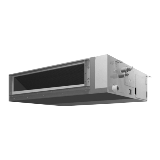
- Page 1 Si071951E REMOVAL PROCEDURE S E R V I C E M A N U A L 5.0/6.0/7.1 kW Class 9000/12000/15000/18000/24000 Btu/h Class Indoor Unit Inverter Duct Connected Type...
- Page 2 Service Manual Removal Procedure Indoor Unit FDMQ09RVJU FMA50RVM4 FDMQ12RVJU FMA60RVM4 FDMQ15RVJU FMA71RVM4 FDMQ18RVJU FDMQ24RVJU FMA50RVMA FMA60RVMA FDMR50TVMG FMA71RVMA FDMR60TVMG FDMR71TVMG FMA50RVMN FMA60RVMN FMA71RVMN FMA50RVMV FMA60RVMV FMA71RVMV...
-
Page 3: Table Of Contents
Si071951E Table of Contents 1. PCBs / Reactor / Terminal Blocks............2 2. Fan Motor / Fan Rotor................5 3. Drain Pan ....................8 4. Thermistors / Drain Pump / Float Switch..........10 5. Indoor Heat Exchanger .................14 Note: The illustrations may be slightly different depending on the model. Removal Procedure... -
Page 4: Pcbs / Reactor / Terminal Blocks
PCBs / Reactor / Terminal Blocks Si071951E 1. PCBs / Reactor / Terminal Blocks Warning Be sure to wait for 10 minutes or more after turning off all power supplies before disassembling work. Step Procedure Points 1. Appearance Discharge side Electrical box cover (R25859) 2. - Page 5 Si071951E PCBs / Reactor / Terminal Blocks Step Procedure Points Remove the screw of Main PCB (A1P) Hook Earth/ground wire the earth/ground wire. Unfasten the 3 hooks and remove the main PCB (A1P). (R25862) 4. Remove the fan PCB [X6A]: reactor (A2P).
- Page 6 PCBs / Reactor / Terminal Blocks Si071951E Step Procedure Points 5. Remove the reactor. Release the reactor harness from the 2 wire clips. Remove the 2 screws, and then the reactor. Reactor Wire clip (R25865) 6. Remove the terminal M4×25 Terminal block (X2M) Terminal block (X1M) blocks.
-
Page 7: Fan Motor / Fan Rotor
Si071951E Fan Motor / Fan Rotor 2. Fan Motor / Fan Rotor Warning Be sure to wait for 10 minutes or more after turning off all power supplies before disassembling work. Step Procedure Points 1. Remove the fan motor ... - Page 8 Fan Motor / Fan Rotor Si071951E Step Procedure Points 3. Remove the fan housing. The number of the fan rotor varies depending on the Unfasten the 2 hooks Hook models. and then remove the fan housing (lower). Fan housing (lower) (R25870) 4.
- Page 9 Si071951E Fan Motor / Fan Rotor Step Procedure Points 5. Remove the fan motor. There is no hook around the fan motor. Always support Loosen the 2 screws. the fan motor to prevent it Hook from dropping off while Unfasten the 2 hooks loosening the screws.
-
Page 10: Drain Pan
Drain Pan Si071951E 3. Drain Pan Warning Be sure to wait for 10 minutes or more after turning off all power supplies before disassembling work. Step Procedure Points 1. Detach the drain hose. If the drain hose is embedded in the wall, Loosen the screw of the disconnect the drain hose... - Page 11 Si071951E Drain Pan Step Procedure Points Remove the 6 screws Some models have 7 screws and the 3 flocked and 4 flocked screws. screws, and then the bottom plate (2). : Flocked screw Bottom plate (2) (R25878) 3. Remove the drain pan. ...
-
Page 12: Thermistors / Drain Pump / Float Switch
Thermistors / Drain Pump / Float Switch Si071951E 4. Thermistors / Drain Pump / Float Switch Warning Be sure to wait for 10 minutes or more after turning off all power supplies before disassembling work. Step Procedure Points 1. Release the harnesses. ... - Page 13 Si071951E Thermistors / Drain Pump / Float Switch Step Procedure Points Cut the clamp and Remove the fan motor/fan Bottom view release the harnesses rotor and drain pan beforehand. for thermistors from the wire clamp material. When reassembling, harnesses for thermistors should be bundled and fixed with the wire clamp material.
- Page 14 Thermistors / Drain Pump / Float Switch Si071951E Step Procedure Points Pull out the drain pump Service cover together with the service cover. Drain pump (R25887) Pull out the harnesses from the service port Bottom view through the wire hole. Wire hole (R25888) Remove the screw, and...
- Page 15 Si071951E Thermistors / Drain Pump / Float Switch Step Procedure Points 3. Remove the drain pump. You may cut the 2 clamps Drain pump (B) for easy access to the Cut the clamp (A) and screws. remove the drain hose. Remove the 3 screws, and then the drain pump.
-
Page 16: Indoor Heat Exchanger
Indoor Heat Exchanger Si071951E 5. Indoor Heat Exchanger Warning Be sure to wait for 10 minutes or more after turning off all power supplies before disassembling work. In pump-down work, be sure to stop the compressor before disconnecting the refrigerant pipe. - Page 17 Si071951E Indoor Heat Exchanger Step Procedure Points 2. Remove the indoor heat Piping cover exchanger. Remove the 4 screws, and then the piping cover. (R25894) Remove the partition Partition plate plate. (R25895) Remove the 5 screws, To prevent the indoor heat and then the indoor exchanger from dropping, be heat exchanger.
- Page 18 Revision History Month / Year Version Revised contents 08 / 2019 Si071951E First edition...
- Page 19 Improper installation can result in water or refrigerant leakage, electrical shock, fire or explosion. Use only those parts and accessories supplied or specified by Daikin. Ask a qualified installer or contractor to install those parts and accessories. Use of unauthorized parts and accessories or improper installation of parts and accessories can result in water or refrigerant leakage, electrical shock, fire or explosion.
Need help?
Do you have a question about the FDMQ09RVJU and is the answer not in the manual?
Questions and answers
dimensions of piping
The piping dimensions for the Daikin FDMQ09RVJU are:
- Liquid piping: φ 6.4 mm
- Gas piping: φ 9.5 mm and φ 12.7 mm
This answer is automatically generated