Daikin FDMQ09RVJU Installation Manual
R410a split series
Hide thumbs
Also See for FDMQ09RVJU:
- Service manual (19 pages) ,
- Operation manual (12 pages) ,
- Manual (152 pages)

Related Manuals for Daikin FDMQ09RVJU


Summary of Contents for Daikin FDMQ09RVJU
-
Page 1: Installation Manual
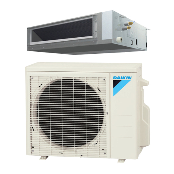
DAIKIN ROOM AIR CONDITIONER INSTALLATION MANUAL R410A Split Series Installation manual Manuel dinstallation Manuel dinstallation Manual de instalación MODELS FDMQ09RVJU FDMQ12RVJU FDMQ15RVJU FDMQ18RVJU FDMQ24RVJU... -
Page 2: Table Of Contents
Additionally, grounding to gas pipes could cause a gas leak specified by Daikin are used, fire or explosion may occur. and potential explosion causing severe injury or death. • If refrigerant gas leaks during installation, ventilate the area immediately. - Page 3 (d) W here flammable gas may leak, where there is carbon CAUTION fiber, or ignitable dust suspension in the air, or where volatile flammables such as thinner or gasoline are • Do not touch the switch with wet fingers. Touching a switch handled. Operating the unit in such conditions can with wet fingers can cause electric shock. cause a fire. • Do not allow children to play on or around the unit to • Take adequate measures to prevent the outdoor unit prevent injury.
-
Page 4: Before Installation
2. BEFORE INSTALLATION 2-2 OPTIONAL ACCESSORIES • A remote controller is required for the indoor unit. When unpacking the indoor unit or moving the unit after • Select a remote controller from the table below according to unpacked, hold the hangers (4 places) and do not apply user request and install in an appropriate place. -
Page 5: Choosing An Installation Site
3. CHOOSING AN INSTALLATION SITE Items to be checked at time of delivery Hold the hangers at 4 locations to move the indoor unit Items to be checked Check when unpacking or after unpacked, and do not apply force to the piping (refrigerant and drain) and air outlet flange. Have you carried out field setting? (if necessary) If the temperature and humidity in the ceiling is likely to Are the electrical wiring box cover, air filter, suction... -
Page 6: Preparation Before Installation
31-1/2 (800) Inspection port 1 <Failure example> 24-13/16 (17-11/16 (450)× If there is an obstacle in the airflow path or proper installation (630) 17-11/16 (450)) space is not provided, the indoor unit will cause air volume (Suspension reduction and take in air blown out of the indoor unit, bolt pitch) Suspension bolt (× 4) thus resulting in performance degradation or turning the thermostat OFF frequently. -
Page 7: Indoor Unit Installation
5. INDOOR UNIT INSTALLATION (4) Open installation holes (in the case of installation onto the existing ceiling). Depending on the optional parts, it may be easier to attach • Open the installation holes on the ceiling of the them before installing the indoor unit. Refer to also the installation location, and work on the refrigerant piping, installation manual attached to the optional parts. -
Page 8: Refrigerant Piping Work
CAUTION WARNING • Install the indoor unit leveled. • Do not apply mineral oil to the flare. If the indoor unit is inclined and the drain piping side gets • Prevent mineral oil from getting into the system as this would reduce the service life of the units. high, it may cause malfunction of float switch and result in water leakage. - Page 9 • The refrigerant is pre-charged in the outdoor unit. Gas Piping Insulation Procedure Tighten Fitting insulation (5) Torque wrench Flare nut Piping insulating Wind around the connection material (unit) piping until top of the Spanner Bring the flare nut connection, Do not leave seam beginning at the base.
-
Page 10: Drain Piping Work
7. DRAIN PIPING WORK <In case of sticking vinyl tape> (1) Carry out drain piping. Tightened part Carry out drain piping so that drainage is ensured. • Select the piping diameter equal to or larger than (except for riser) that of the connection piping (polyvi nyl chloride piping, nominal diameter 1 inch Vinyl tape (25mm), outside diameter 1-1/4 inch (32mm)). - Page 11 • If a qualified person is not present, after the electric CAUTION wiring work is finished, check the drainage accord i ng • To avoid the attached drain hose (2) getting excessive to the method specified in [When the electric wiring force, do not bend nor twist it. work is finished]. It may cause water leakage. 1. Open the electrical wiring box cover and connect the • As for drain piping connection, do not connect the drain ground wiring to the ground terminal.
-
Page 12: Duct Work
8. DUCT WORK 9. ELECTRIC WIRING WORK Pay the utmost attention to the following items and 9-1 GENERAL INSTRUCTIONS conduct the duct work. • Make certain that all electric wiring work is carried out by • Check that the duct is not in excess of the setting range of qualified personnel according to the applicable legislation external static pressure for the unit. - Page 13 9-2 WIRING EXAMPLE 9-4 WIRING CONNECTION METHOD For the wiring of outdoor units, refer to the installation manual CAUTION FOR WIRING attached to the outdoor units. Confirm the system type. • For connection to the terminal block, use ring type crimp • Multi system: 2 through 6 (The number of connectable units style terminals with insulation sleeve or insulate the wirings will vary according to model) indoor units connect to 1 outdoor properly.
- Page 14 (2) Attach the conduit to the conduit mounting plate (12). (4) Follow the instructions below and perform wiring in the electrical wiring box. Conduit mounting plate (12) Terminal block (X1M) Power supply terminals (X1M) for wiring between the Conduit Outdoor unit Indoor unit indoor and outdoor units (field supply)
-
Page 15: Field Setting
10. FIELD SETTINGS (1) Check that the electrical wiring and duct work have been completed. CAUTION (If the closing damper is set midway, be sure to check that the damper is opened. Furthermore, check that the air Before carrying out field setting, check the items mentioned in passage on the suction side is provided with an air filter 1. Items to be checked after the installation work is (field supply)). -
Page 16: Trial Operation And Testing
11. TRIAL OPERATION AND TESTING (b) Select external static pressure with the remote controller. Check with Mode No. [21] per indoor unit that the SECOND CODE No. for the above “Air volume adjustment” is set to “01” 11-1 TRIAL OPERATION AND TESTING (OFF). - Page 17 For wired remote controller Basic screen 1) Set to COOL or HEAT operation using the remote Cool controller. Set to Cool Press and hold Cancel 2) Press and hold Cancel button for 4 seconds or longer. button for 4 seconds or Service settings menu is displayed. Return Clean the filter longer during backlight lit.
- Page 18 „ Diagnose with the display on the liquid crystal display For wireless remote controller remote controller. MODE 1) Press and select the COOL or HEAT operation. With the wired remote controller /TEST When the operation stops due to a malfunction, operation 2) Press twice.
- Page 19 11-3 MALFUNCTION CODE Action of safety device • For places where the malfunction code is written in white, (Outdoor unit) the “ ” indication is not displayed. Though the system Outdoor Printed Circuit continues operating, be sure to inspect the system and make Board failure (Outdoor unit) repairs as necessary.
- Page 20 Heat-radiating fin Abnormal stop is applied thermistor malfunction depending on the model or (Outdoor unit) condition. The refrigerant may be insufficient. Suction piping temperature Abnormal stop is applied abnormal (Outdoor unit) depending on the model or condition. The inverter open-phase or main circuit condenser may Power voltage malfunction be malfunctioning.
- Page 21 English...
- Page 22 The two-dimensional bar code is a manufacturing code. 3P500432-1 M17B179 (1711) HT...
Need help?
Do you have a question about the FDMQ09RVJU and is the answer not in the manual?
Questions and answers