Table of Contents
Advertisement
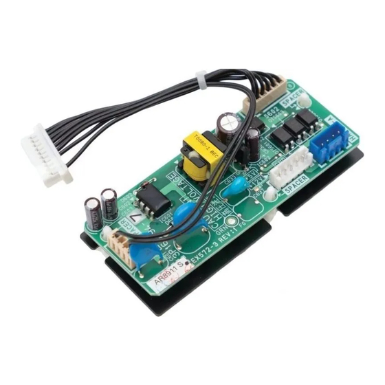
INTERFACE ADAPTER-AOR
DTA119A71
INSTALLATION MANUAL
IMPORTANT SAFETY INSTRUCTIONS
The following symbols and labels are used throughout this manual to indicate
immediate or potential safety hazards. It is the owner's and installer's
responsibility to read and comply with all safety information and instructions
accompanying these symbols. Failure to heed safety information increases
the risk of personal injury, property damage, and/or product damage.
HIGH VOLTAGE!
DISCONNECT ALL POWER BEFORE SERVICING.
MULTIPLE POWER SOURCES MAY BE PRESENT.
FAILURE TO DO SO MAY CAUSE PROPERTY DAMAGE,
PERSONAL INJURY OR DEATH.
ONLY PERSONNEL THAT HAVE BEEN TRAINED TO INSTALL, ADJUST,
SERVICE OR REPAIR (HEREINAFTER, "SERVICE") THE EQUIPMENT
SPECIFIED IN THIS MANUAL SHOULD SERVICE THE EQUIPMENT.
THE MANUFACTURER WILL NOT BE RESPONSIBLE FOR ANY INJURY
OR PROPERTY DAMAGE ARISING FROM IMPROPER SERVICE OR
SERVICE PROCEDURES. IF YOU SERVICE THIS UNIT, YOU ASSUME
RESPONSIBILITY FOR ANY INJURY OR PROPERTY DAMAGE WHICH
MAY RESULT. IN ADDITION, IN JURISDICTIONS THAT REQUIRE ONE
OR MORE LICENSES TO SERVICE THE EQUIPMENT SPECIFIED IN
THIS MANUAL, ONLY LICENSED PERSONNEL SHOULD SERVICE THE
EQUIPMENT.
IMPROPER INSTALLATION, ADJUSTMENT, SERVICING OR REPAIR OF
THE EQUIPMENT SPECIFIED IN THIS MANUAL, OR ATTEMPTING TO
INSTALL, ADJUST, SERVICE OR REPAIR THE EQUIPMENT SPECIFIED IN
THIS MANUAL WITHOUT PROPER TRAINING MAY RESULT IN PRODUCT
DAMAGE, PROPERTY DAMAGE, PERSONAL INJURY OR DEATH.
WARNING
WARNING
Advertisement
Table of Contents

Related Manuals for Daikin DTA119A71


Summary of Contents for Daikin DTA119A71
-
Page 1: Important Safety Instructions
INTERFACE ADAPTER-AOR DTA119A71 INSTALLATION MANUAL IMPORTANT SAFETY INSTRUCTIONS The following symbols and labels are used throughout this manual to indicate immediate or potential safety hazards. It is the owner’s and installer’s responsibility to read and comply with all safety information and instructions accompanying these symbols. -
Page 2: Table Of Contents
Index IMPORTANT SAFETY INSTRUCTIONS .........1 SHIPPING INSPECTION ..............3 CODES & REGULATIONS .............3 FEATURES ..................4 ACCESSORIES ................4 SAFETY CONSIDERATIONS ............5 APPLICATION .................7 INSTALLATION ................8 ELECTRIC WIRING WORK ............9 WIRING DIAGRAM ...............10 DEHUMIDIFICATION SETTING ............12 TROUBLESHOOTING ..............17 English... -
Page 3: Shipping Inspection
SHIPPING INSPECTION Shipping damage, and subsequent investigation is the responsibility of the carrier. The distributor or manufacturer will not accept claims from dealers for transportation damage or installation of incorrectly shipped units. CODES & REGULATIONS This product is designed and manufactured to comply with national codes. Installation in accordance with such codes and/or prevailing local codes/ regulations is the responsibility of the installer. -
Page 4: Features
This adapter is designed to be compatible with any non-communicating gas furnaces. The adapter may ONLY be paired with Daikin One+ Smart Thermostat as part of the digital communicating system. -
Page 5: Safety Considerations
SAFETY CONSIDERATIONS Read these Safety considerations for Installation carefully before installing the adapter. After completing the installation, make sure that the unit operates properly during the system start-up operation. Instruct the customer on how to operate and maintain the unit. Inform customers that they should store this Installation Manual for future reference. - Page 6 • USE ONLY SPECIFIED ACCESSORIES AND PARTS FOR INSTALLATION WORK. FAILURE TO USE SPECIFIED PARTS COULD RESULT IN WATER LEAKAGE, ELECTRIC SHOCKS, FIRE, OR THE UNIT FALLING. • INSTALL THE ADAPTER ON A PLACE STRONG ENOUGH THAT IT CAN WITHSTAND THE WEIGHT OF THE UNIT. A PLACE OF INSUFFICIENT STRENGTH COULD RESULT IN THE UNIT FALLING AND CAUSING INJURIES.
-
Page 7: Application
NOTICE All AHRI (Air Conditioning, Heating and Refrigeration Institute) system ratings are accessible in the unitary matchup tool via DAIKIN CITY or in the DAIKIN system configurator tool via PartnerLink. Allowable Air flow CFM range Rated performance is based on fan speed changing under low load conditions. -
Page 8: Installation
NOT ON A-coil NOT ON GAS FURNACE Do NOT mount DTA119A71 to any supply duct. Also, avoid mounting the adapter directly to any air handler, furnace, hot water coil or evaporator cabinet in the area. Otherwise, this may cause damages to those parts. -
Page 9: Electric Wiring Work
ELECTRIC WIRING WORK 1. Connect the wires to the devices according to the wiring diagram. The connections are different due to different gas furnace (single-stage or two-stage). 2. Connect the ground wire to the grounding screw. Attach wiring ⑤ terminal ( ) to PCB board. -
Page 10: Wiring Diagram
250 ft, from the adapter to gas furnace should be less than 100 ft, and from the adapter to Daikin One+ Smart Thermostat should be less than 125 ft. Wire with thermostat, indoor a-coil, outdoor unit and gas furnace according to the wiring diagram. - Page 11 WIRING DIAGRAM FOR THE SINGLE-STAGE FURNACE APPLICATION OF ADDING A RELAY (Thermostat and A-coil wiring omitted) INTERFACE ADAPTER 2 R C G W1 W2 GAS FURNACE (SINGLE-STAGE) 24V AC SUPPLY POWER PCB TERMINAL Heat-Hi Cool-Hi *(Note) (Heat-Hi speed)** (Cool-Hi speed)** (Cool-Lo speed)** 24VAC SPDT...
-
Page 12: Dehumidification Setting
DEHUMIDIFICATION SETTING The dehumidification performance will be improved by changing the setting in Daikin One+ Smart Thermostat to “A” or “B” or “C”. Accordingly, the minimum compressor speed will be locked due to different setting. For example, by selecting “C” the minimum compressor speed will be fixed at 100% dehumidification capability. - Page 13 DEHUMIDIFICATION SET-UP ON Daikin One+ Smart Thermostat For a system using the adapter, Daikin One+ Smart Thermostat allows customers to have a dehumidification profile setting to achieve different dehumidification performance due to different requirements. Navigating to dealer edit will allow you to access the dehumidification set-up.
- Page 14 7. Find the unique installer code and enter the code, click “done” to unlock thermostat. → Example: c0fe 8. Choose the language and click “continue”. 9. Select “unitary” and click “continue”. 10. Select “begin setup”. 11. Choose “equipment setup”. English...
- Page 15 12. Select “air conditioner”, which is the outdoor unit in the system. 13. Select “cool settings”. 14. Select “dehumidification”. 15. Select one of the settings according to your demand at this display. “off” means no special dehumidification profile setting. “A” has the less dehumidification performance than the default setting “B”, while “C”...
- Page 16 “HOME” screen. 7-SEGMENT DISPLAY SCREEN 3 (SETTING MODE 1) Setting No. Contents Setting Installer/Service Notes 0:STD Dehumidification Select 1:OFF This setting can be set with Daikin One+ Smart Thermostat or 7-segment. Please adjust the setting according to customer request. English...
-
Page 17: Troubleshooting
When the gas furnace shows any abnormal condition, refer to relevant manual for the gas furnace. Check the installation restrictions of each unit. The latest Installation Manual can be obtained from the website “DAIKIN CITY (Installation Manual/Unitary Split System)” or “PartnerLink (Info-FinderPlus/ Literature)”. - Page 18 NOTES English...
- Page 20 CUSTOMER FEEDBACK Daikin is very interested in all product comments. Please fill out the feedback form on the following link: https://daikincomfort.com/contact-us You can also scan the QR code on the right to be directed to the feedback page. NOTE: SPECIFICATIONS AND PERFORMANCE DATA LISTED HEREIN ARE SUBJECT TO CHANGE WITHOUT NOTICE ©...
Need help?
Do you have a question about the DTA119A71 and is the answer not in the manual?
Questions and answers