Table of Contents
Advertisement
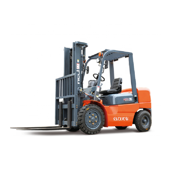
The performance, structure, operation and maintenance and other aspects of the K
series 2-3.8t forklift truck are described in this manual in order to guide the operators
to use and maintain the truck properly.
The rules and notices in the manual should be abided seriously by all of relative
person to enable trucks in optimized working state for long period and bring the
highest efficiency.
FORWARD
Advertisement
Table of Contents


Need help?
Do you have a question about the CPC 20 and is the answer not in the manual?
Questions and answers