Table of Contents
Advertisement
Quick Links
H3-series CPCD40, CPCD45, CPCD50, CPQD40, CPQD45, CPQD50, CPYD40,
CPYD45, CPYD50 ,CPQYD40, CPQYD45, CPQYD50 internal combustion counterbalanced
forklift trucks-material handling machines that are driven by front axle, and steered by rear
axle. Trucks are used for materials handling, loading and discharging, and piling piece cargo
at the goods yard, station, port, building site and plant, also used to transport in short distance.
For such features: Luxury exterior, fine streamline, low noise and pollution, flexible
operation, wide view mast, safety and reliability, shock absorption, dustproof, fine tractate and
traveling ability, fine riding comfort, trucks are regarded as ideal equipments to accomplish
the mechanization of loading and unloading.
There will have a wider use if trucks are fitted with all kinds of the attachments (such as
side shift, rotator, paper roll clamps, fork petitioners and so on).
This manual describes the performance, construction, operation and maintained of the
above trucks. Before putting the forklift trucks into use, please read the manual carefully in
order to ensure the proper operation of the forklift trucks.
To improve our forklift trucks, absorb your valuable suggestion; please send to us
suggestion content.
We also ask your understanding for the fact that, due to on-going improvement of parts
and equipment, the numerical values given in the manual are subject to change without notice.
FOREWORD
Advertisement
Table of Contents
Troubleshooting

Related Manuals for HELI H3 Series


Summary of Contents for HELI H3 Series
- Page 1 FOREWORD H3-series CPCD40, CPCD45, CPCD50, CPQD40, CPQD45, CPQD50, CPYD40, CPYD45, CPYD50 ,CPQYD40, CPQYD45, CPQYD50 internal combustion counterbalanced forklift trucks-material handling machines that are driven by front axle, and steered by rear axle. Trucks are used for materials handling, loading and discharging, and piling piece cargo at the goods yard, station, port, building site and plant, also used to transport in short distance.
-
Page 2: Table Of Contents
CONTENT FOREWORD .......... - Page 3 ..........
- Page 4 ..........
-
Page 5: I.features
I.FEATURES H3-series CPCD40, CPCD45, CPCD50, CPQD40, CPQD45, CPQD50, CPYD40, CPYD45, CPYD50, CPQYD40, CPQYD45, CPQYD50 forklift truck adopt the drive way: engine- hydraulic torque converter-gearbox-driving axle. Features are showed on the following: (1) Because of adopting hydraulic drive, guard against engine stopping under the overload condition, If load capacity are increased sharply, meanwhile, accomplish smooth shifting operation. -
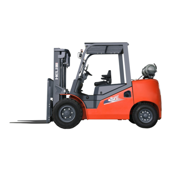
Page 6: Ii.external View And Main Performance Table
II.EXTERNAL VIEW AND MAIN PERFORMANCE TABLE 1. EXTERNAL VIEW OF THE INTERNAL MACHINE ¦Â ¦Á... -
Page 7: Main Performance Table
2.Main Performance Table of H Series 4-5t Forklift Truck: CPCD40-xxxH CPCD45-xxxH CPCD50-xxxH CPQD40-xxxH CPQD45-xxxH CPQD50-xxxH Model CPCD50-xxxHS CPYD40-xxxH CPYD45-xxxH CPYD50-xxxH CPQYD40-xxxH CPQYD45-xxxH CPQYD50-xxxH 4000 4500 5000 5000 Rated load Lord center 3000 Max. Lift height Free Lift height 6/12 Tilt angle FWD/BWD °... - Page 8 CPCD40-xxxH CPCD45-xxxH CPCD50-xxxH CPQD40-xxxH CPQD45-xxxH CPQD50-xxxH Model CPCD50-xxxHS CPYD40-xxxH CPYD45-xxxH CPYD50-xxxH CPQYD40-xxxH CPQYD45-xxxH CPQYD50-xxxH 19.5 Rated pressure 18.5 Pump Model CBKEC-G25-ATφL CBKEC-G25-ATφ valve mode mL/r 25×2 Control valve model CDB-F20 Diameter×Stroke(lift) 70×1489 Diameter×Stroke(tilt) 90×201 8.25-15-14PR 300-15-18PR 300R15 Front wheel 8.3 x10 Pneumatic 8.3×10 10×10...
-
Page 9: Iii.construction And Performance Of Main Parts
III.CONSTRUCTION AND PERFORMANCE OF MAIN PARTS 1. ENGINE: Table No.1 Engine model DIESEL DIESEL DIESEL DIESEL DIESEL 4C6 88C33 4DX23 YN4E V3800 Main performance Rated Output(KW) 61.6 2200 2200 2200 2300 2200 Rated speed (rpm) 350/1700 320/1400-1600 400/1300-1800 248/1700 310/1600 Max. -
Page 10: General Description
Transmission Type: Power-shift constant mesh Gear Ratio: fwd 3.452/2.125 rev 2.72 Clutch Clutch facing size (mm): 134×90×2.8 Surface area: 7740(mm )×12 Pressure setting: 12-15kg/cm Oil to be used: Torque converter oil 20L Differential Reduction Ratio: 6.333 Weigh: 184kg Oil to be used: Torque converter oil 7L 2-1 GENERAL DESCRIPTION The power-shift transmission mounted on this series forklift truck is designed and made... -
Page 11: Torque Converter
Fig.2-1 Torque Converter Type Transmission 1. Tor-con ass’y 3. Tor-con front case 2. Plate 6. Shaft 4. Tor-con rear case 5.Pump shaft 9. Case 7. Changing pump ass’y 8.Cap 10. Hydraulic clutch 11. FWD 2nd speed clutch 12. Output shaft 13.Output flange 2-2 TORQUE CONVERTER The torque converter consists primarily of a pump wheel connected to the input shaft, a... -
Page 12: Clutch Grous
reaction torque. As a result of this the output shaft torque becomes smaller than the input shaft torque. To prevent this condition, a free wheel (one –way clutch) is provided at the stator section to allow the stator wheel to rotate freely when reaction torque acts in the reverse direction. -
Page 13: Control Valve
outer circumferences encase to insure oil sealing during operation. The piston has a check ball to prevent dragging. The clutch surface and gear bushings are always lubricated with oil to prevent seizure. When replacement of any clutch disk is needed, the mating steel plate should also be changed. Fig.2-3 Clutch group 1. -
Page 14: Oil Circulation Route
Fig.2-4 Control Valve 1. Valve 2. Bolt 3. Washer 4. Directional selector electromagnetic valve 5. Speed electromagnetic valve 2-5 OIL CIRCULATION ROUTE When the engine is stared and the charging pump is driven by the pump drive gear fitted to the pump wheel boss, torque converter oil drawn from the oil tank (transmission case) through the strainer by the pump and is routed under pressure to the main regulator valve and the control valve in the converter housing. - Page 15 controlled by the pressure control mechanism to the specified pressure. When the change lever is put in forward or in reverse, the oil is sent from the control valve through the forward/reverse selector valve to the pressurization chamber of the forward or the reverse clutch.
-
Page 16: Charging Pump
2-6 CHARGING PUMP The charging pump is a gear type and is installed in the torque converter housing, It feeds oil to the torque converter, hydraulic clutches and transmission to lubricate them. The charging pump consists of the drive gear, driven gear, case and cover, see Fig.2-6. Fig.2-6 Charging Pump 2-7 DIFFERENTIAL The differential is fitted to the rear case (reduction gear case) by ball bearings with... -
Page 17: Differential Maintenance
Fig. 2-7 Differential 1.Ring gear 2. Thrust washer 3.Side gear 4. Cross case 5. Pinion shaft 6. Pinion gear 7. Thrust washer 8. Drive pinion gear 9. Lock nut 10. Tapered roller bearing 11. Oil seal 12.Flange 13.Cap 14. Packing seal 15. -
Page 18: Front Axle
Adjustment should be made by using the shims between the tapered roller bearing and spacer Shims: 0.1, 0.15, 0.2, 0.5, 2.3, 2.6 mm (5)Adjust the backlash between the drive pinion and ring gear to the specified torque. Backlash: 0.23~0.33mm Adjustment should be made by using the shims between the bearing case and the carrer. Adjust the engagement either. - Page 19 Fig.3-1 Front Axle 1. Hosing 2. Wheel brake 3. Brake drum 4.Oil seal 5.Bearing 6. Bearing 7. Axle shaft 8. Bolt 9. Oil seal 10. Nut 11.Nut 12.Bolt -15-...
-
Page 20: Axle Housing
3-2 AXLE HOUSING The axle housing is a one –piece construction consisting of a banjo-shaped differential housing and spindle and is secured to the frame with ban sector. 3-3 FRONT WHEEL HUB The front wheel hub receives the power from the differential through the drive shaft and drives the front wheels. -
Page 21: Brake System
[4]Tighten all outer wheel nuts to the specified torque. Tightening torque: 480~560N.m Notes: If remove sand or any other contamination on the mating surfaces of the rim and the hub and on the thread of the nuts or stud bolts. 4. -
Page 22: Wheel Brake
Fig.4-1 Brake pedal (Torque Converter Model) 4-3 WHEEL BRAKE (Fig.4-2) The wheel brake is the internal expansion hydraulic type consisting of brake shoes, springs, a wheel cylinder, an adjuster and backing plates. Two wheel brakes are provided on each end or the front axle. The brake shoe, its one end being connected to the anchor pin and the other end to the adjuster, is forced against the backing plate with a hold spring and pin. - Page 23 Fig.4-2 Wheel Brake 1. Retainer 2. Wheel Cylinder 3. Cup 4. Piston 5. Push rod 6. Strut 7. Return spring 8. Brake shoe 9. Hold-down pin 10. Cap 11. Spring 12. Spring 13. Adjuster lever 14. Adjuster The braking operation in forward travel is as follows: (see Fig.4-3) the primary and secondary shoes are forced by an equal force, by operation of the wheel cylinder to bring the lining in contact with the brake drum.
-
Page 24: Parking Brake
Anchor pin Working force Working force Adjusrer Fig.4-3 In Forward Fig.4-4 In Reverse 4-4 PARKING BRAKE The parking brake consists of the parking brake lever and cable as shown in Fig.4-5. The brake shoes and brake drum are commonly used with the wheel brake system. The brake lever is a toggle type which allows the adjustment of braking force with the adjuster at the tip or the lever. -
Page 25: Automatic Clearance Adjuster
4-5 AUTOMATIC CLEARANCE ADJUSTER The automatic clearance adjuster keeps a lining to break drum clearance of 0.4~0.6mm automatically. This adjuster, however, actuates only when the truck is braked in reverse travel. When the break pedal is pressed in reverse travel, the brake shoes are expanded. As a result of this, the secondary and primary shoes come into contact with the brake drum and rotate together until the upper end of the primary shoe comes into contact with the anchor pin. -
Page 26: 4-7.Maintenance
Fig.4-6 Power Break Booster 1. Body 2. Cup 3. Flow divider 4. Spring 5. check valve 6. Plug 7. Stopper 8. Piston 9. Power piston 10. Control valve 11. Seat 12. Reaction piston 13. Push rod 4-7 MAINTENANCE This paragraph covers the procedures for disassembling, reassembling and adjusting the wheel brake, and the procedure for adjusting the brake pedal. - Page 27 (2) Remove the shoe return spring. Fig.4-8 (3) Remove the primary shoe hold-down spring. Fig.4-9 (4) Remove the primary and secondary shoes along with the adjuster and adjuster spring. Fig.4-10 -23-...
- Page 28 (5) Remove the brake pipe from the wheel cylinder. Remove the wheel cylinder mounting bolts and take the wheel cylinder off the backing plate. Fig.4-11 (6) Remove the "E" retainer securing the parking brake cable to the backing plate. Remove the backing plate fitting bolts and detach the backing plate from the axle. Fig.4-12 (7) Remove the boot, and push the piston into the cylinder from one side while removing the parts at the other side.
- Page 29 (1)Inspect the wheel cylinder’s inner surface and piston’s outer surface for sign of rust. Measure the clearance between the piston and cylinder. Specified value: 0.03-0.10mm Limit: 0.15 mm (2)Visually check the piston cup for damage or deformation and replace it, if defective, with a new one.
- Page 30 (1)Measure the free length and setting load of the anchor side shoe return spring. (2)Check the adjuster for damage and operation, and the contact area between the pole lever and the gear for defect. Replace if necessary. 4-7-3 WHEEL BRAKE REASSEMBLY (1)Apply brake fluid to the wheel cylinder cup and piston, and reinstall the spring, piston cup, piston and boot in that order.
- Page 31 Fig.4-18 (1)Put the anti-rattle spring in the strut and install them on the shoe. (2)Install the shoe guide pin on the anchorpin. Install the shoe return spring. For this procedure, start with the primary shoe and then proceed with the secondary one. Fig.4-19 (1)Install the spring, adjuster, adjuster spring and adjuster lever, observing the following points:...
- Page 32 Fig.4-20 (10) Install the brake pipe on the wheel cylinder. (11) Measure the brake drum inner diameter and the shoe outer diameter. Adjust the adjuster so that the brake shoe outer diameter is drum inner diameter-1.0mm. Fig.4-21 4-7-4 OPERATION TEST OF AUTOMATIC CLEARANCE ADJUSTER (1) Make the brake shoe diameter nearly to the specified setting size, and pull the adjuster lever by your hand to turn the adjuster gear.
-
Page 33: Brake Pedal Adjustment
Fig.4-22 4-7-5 BRAKE PEDAL ADJUSTMENT (1) Shorten the master cylinder push rod properly. (2) Adjust the pedal height with the stopper bolt as shown in Fig.4-23. (3) Keeping the pedal pressed 30mm, extend the push rod so that the its end contact the master cylinder piston. -
Page 34: Air Bleeding
4-7-6 BRAKE SWITCH ADJUSTMENT (1) After making sure that the brake pedal height is as indicated in Fig.4-23, loose the brake switch lock nut. (2) Remove the brake switch lead wire from the connector. (3) Turn the switch so that the size at “A” is 1mm. (4) Make sure the brake lamps turn on when the brake pedal is pressed 30mm. -
Page 35: Trouble Shooting Of The Brake System
4-8 TROUBLE SHOOTING OF THE BRAKE SYSTEM Remedy Problem Probable cause 1.Fluid leaks from brake system Repair 2.Maladjustment of brake shoe clearance Check and adjust adjuster 3.Overheated brake Check for dragging 4.Poor contact between brake drum and lining Adjust contact 5.Foreign matter adhered to lining Repair or replace 6.Foreign matter mixed in brake fluid... -
Page 36: Steering System (Orbitrol Type)
5.STEERING SYSTEM (ORBITROL TYPE) Type Center-pin supported King pin spacing 1020mm King pin angle 0° Steering axle Ton-in 0° Camber 1° Caster 0° Inner wheel 78°42′ Steering axle Outer wheel 54°36′ Type Open-entered, no-load reaction type Redirector Discharge 200ml/r Pressure 12.5MPa Type Double-acting piston type... -
Page 37: Steering Axle
5-2 STEERING AXLE The steering axle is of steel-welded construction with a box shaped cross section, incorporating a steering cylinder inside it. See Fig.5-1. The steering cylinder is housed in the axle to protect it from being damaged by obstacles on the road surface. The axle is installed onto the truck frame through a center pin with bushing and cap, and it cradles around this center pin. -
Page 38: Orbitron
Fig.5-2 Steering Wheel Assembly 5-4 ORBITRON The orbitrol of model BZZ cycloidal type is open-centered, no-load reaction device (Fig.5-3). The rotor and the stator is a pair of cycloidal pin gear internal mesh gears. It is serried between the flow dividing valve and the steering cylinder during normal operation, it operated as an oil motor. The turning angle is direct proportion with the oil which flows to or from the steering cylinder because the oil must flows through the oil motor. - Page 39 Fig.5-3 Orbitrol 1. Retainer 2. Head cap 3. Valve 4. Spring 5. Shift arm 6. Sleeve 7. Valve core 8. Drive shaft 9. Rotor 10. End cap 11. Spacer 12. Stator 13. “O”-ring 14. Steel ball 15. “O”-ring 16. “X”-ring 17.
- Page 40 20 21 14 13 23 1 15 11 16 Fig.5-4 (b) When steering wheel is turned counter-clockwise As the steering wheel is turned counter-clockwise, the grooves in the spool shift to the left in relation with the holes and grooves in the sleeve so that holes (4) in the spool get out of line with holes (3) in the sleeve.
- Page 41 The returning oil from the steering cylinder flows, assign through the cylinder port R, groove (11) in the valve housing, oil hole (17) in the sleeve, groove (19) in the spool, oil hole (22) in the sleeve, and groove (8) in the valve housing, back to the oil tank. 20 21 10 11 Fig.5-5...
- Page 42 sleeve to the cylinder port R in the housing and thus actuates the steering the steering cylinder. The returning oil from the steering cylinder flows, passing through the cylinder port L, groove (10) in the housing, oil hole (18) in the sleeve, groove (19) in the spool, oil hole (22) in the sleeve and groove (9) in the housing back to the oil tank.
-
Page 43: 5-5.Steering Cylinder
(3) Neutral feedback of orbitrol The neutral feedback of the orbitrol is performed by changing-over in oil passages of the valve, due to the reactions force of centering spring. (When the steering wheel is turned and then released with the engine at rest, the steering wheel returns to the initial position.) Unless the nevtral feedback is completely performed, the steering wheel may be turned, even through the operator does not turn the steering wheel. -
Page 44: Trouble Shooting
5-6 TROUBLE SHOOTING Remedy Problem Possible cause Defective or damaged pump Replace Steering wheel Relief vale stuck or damaged Clean or replace won't operate Control valve stuck, damaged, or worn Replace or repair Damaged hose joint or clogged oil line Replace or clean Low oil level in oil tank Add oil... -
Page 45: Hydraulic System
6.HYDRAULIC SYSTEM Model CBKEC-G25-ATφL/ CBKEC-G25 -ATφ Type Gear type Main pump Drive Speed box PTO Discharge 50ml/r Loaded pressure 20MPa Model CBD-F20U Spool sliding type, with relief valve, tilt lock valve, and Control valve Type flow divider. Pressure setting 18.5MPa(4-4.5t)/19.5 MPa(5t) Type Single acting piston with flow regulator. -
Page 46: Flow Dividing Valve
Tilt Cylinder Steering Cylinder Steering Capacity:12L/min Lift Cylinder Break Valve To Break Pump Lood Sensor Redirector Fig.6-1 Hydraulic System Principle Diagram 6-2 FLOW DIVIDING VALVE (Fig.6-2) The model of the flow-dividing valve is 21730-40667 type (the home type is 1WFL- F15L-6). -
Page 47: Control Valve
Outlet Parallel feeder Relief valve Parallel feeder Lift valve Tilt valve Flow dividing valve Fig.6-2 Flow Dividing Valve 6-3 CONTROL VALVE The model of the control valve is CBDF-F20U, unit combination type. Add control valves if needs. The valve’s function is carrying respectively high pressure oil came from oil pump to each hydraulic cylinder, making back oil returning to the tank, and changing the flow direction by operating control lever.(Fig.6-3) The control valve consists of an inlet section. -
Page 48: Return Spring
LOAD CHECK VALVE PARALLEL FEEDER CYLINDER PORT B CYLINDER PORTA RETURN SPRING PLUNGER NEUTRAL PASSAGE LOW-PRESSURE PASSAGE Fig.6-3 Control Valve (1)Plunger operation (a)In neutral state(Fig.6-4) The oil disc harged from the pump flows through the neutral passage back to the oil tank. The ports “A”... - Page 49 Fig.6-5 (a)When plunger is drawn out (Fig.6-6) with the neutral passage closed, the oil pushes up the load check valve, passing through the parallel feeder, and flows into the cylinder port “A”. The returning oil from the cylinder port “B” flows through the low-pressure passage to the tank.
-
Page 50: Tilt Cylinder
Fig.6-8 (a)As the pilot poppet “E” opens. The pressure behind the poppet “D” drops. The inside pressure becomes imbalanced against the pressure at the high-pressure passage side “HP” so that the popper “D” is opened to this pressure differential. Thus allowing the oil to flow directly to the low-pressure passage “LP”... - Page 51 (1)Tilt lock valve operation The control valve in the tilt cylinder circuit has a spool incorporating a tilt lock valve to prevent the mast from vibrating due to possible creation of negative pressure in the tilt cylinder and also to avoid danger incurred from mishandling of the tilt lever. (Fig.6-11) PORT A PORT B PLUNGER...
-
Page 52: 6-4.Lift Cylinder
6-4 LIFT CYLINDER The lift cylinders are the single-acting type and are located behind the outer mast frame. The bottom of each cylinder is supported by the mast support of outer mast frame with knock pin and bolts. The piston head is held by the inner mast piston head guide. The lift cylinder assembly consists primarily of a cylinder body, piston, piston rod, cylinder cap, and piston head. -
Page 53: 6-5.Flow Regulator Valve
Fig.6-14 Lift Cylinder 1. Piston Rod 2. Dust Seal 3. Seal Ring 4. Bushing 5. O-ring 6.Guide sleeve 7. Cylinder Cap 8. Cylinder Body 9.Spacer 10.Snapring 11. Piston 12. Bushing 13. Seal washer 14. Seal Ring 15. Washer 16.Sleeve 6-5 FLOW REGULATOR VALVE The flow regulator valve controls the fork descending speed and servers as a safety device if the rubber hose ruptures between the control valve and the lift cylinders. -
Page 54: 6-6.Tilt Cylinder
Fig.6-15 Flow Regulator Valve 1. nipple 2. Spring 3. “O”-ring 4. Snap Ring 5. Orifice 6. Sleeve 7. Piston 8. Ball 9. Spring 10. Casel 6-6 TILT CYLINDER (Fig.6-16) The tilt cylinder is a double-acting type, and its piston rod end is supported by the mast and the cylinder tail is connected to the frame with a pin. -
Page 55: 6-7.Trouble Shooting
6-7 TROUBLE SHOOTING Remedy Problem Cause The oil within the cylinder is not enough Add oil to the specified lever. The pump does not operate The pipe or the filter is struck. Clean, change oil if necessary. The bearing in the pump is worn. Replace The pressure of the relief is not right. -
Page 56: Load Handling System
7.LOAD HANDLING SYSTEM Only for 2-stage standard mast. Rolling type 2-stage telescopic mast with free lift(J- Type shaped inner rail and C-shaped outer rail) Φ123 O.D. of end roller Φ50 O.D. of side roller Φ55×Φ135×Φ155 O.D. of chain wheel LH1634 Lift chain CG92310T Upper roller... -
Page 57: 7-3.Lift Chain
plate of mast is same as that above about inner and outer mast. Fork and bracket can run up or down in the inner mast. The distance between two forks can be adjusted according to needs; its range is from 300mm to 1340mm 7-3 LIFT CHAIN The lift chain is flat type chain. -
Page 58: Signal And Operation
In addition the wiring is further divided into meter panel wiring, frame wiring, overhead guard wiring, rear lamp wiring and engine wiring, each connected with couplers. 8-2 SIGNAL AND OPERATION (1)Starter switch: a. Turn to right 1st to connect the meter and equipments supplied by power. b. - Page 59 within the fuel tank. (10)Water temperature meter: It shows the temperature of cooling water. The indicator pan is classified by three colors to show three ranges of the temperature. The engine can be operated under normal conditions when the hand is between green ranges. (11)Hour meter: It works when the truck is driven, and shows the working times of the truck.
-
Page 60: Wiring Diagrams
8-3 WIRING DIAGRAMS 8-3-1 The electrical syetem copmosition. Fig.8-1 The electrical syetem composition 1.Overhead line 2.Combination Instrument 3. Combination switch Starter relay Electric wire plan 6.Vehicle line 7.Integrated electrical box 8.Storage battery 9.Rear combination lamp line 10.Alarm lamp -56-... - Page 61 8-3-2 Diesel engine electrical system schematic diafram(Model 4D35ZG31、4C6-85U32) Fig.8-2 -57-...
- Page 62 8-3-3 Diesel engine electrical system schematic diafram(Model 4DX23) Fig.8-3 -58-...
- Page 63 8-3-4 Diesel engine electrical system schematic diafram(Model YN4E) Fig.8-4 -59-...
- Page 64 8-3-5 Diesel engine electrical system schematic diafram(Model S6S) Fig.8-5 -60-...
- Page 65 8-3-6 Diesel engine electrical system schematic diafram(Model V3800) Fig.8-6 -61-...
- Page 66 8-3-7 Diesel engine electrical system schematic diafram(Model PSI4.3L-DF) Fig.8-7 -62-...
- Page 67 8-3-8 Diesel engine electrical system schematic diafram(Model PSI4.3L-LP) Fig.8-8 -63-...
- Page 68 8-3-9 Diesel engine electrical system schematic diafram(Model PSI4.3L-GAS) Fig.8-9 -64-...
-
Page 69: Operation, Safety Instruction And Maintenance
IV. OPERATION, SAFETY INSTRUCTION AND MAINTENANCE 1. OPERATION AND INSTRUMENT Operation and instruments of the forklift truck refer to the drawings. OPERATION AND INSTRUMENT 1.Parking brake lever 2.Lamp switch 3.Steering wheel 4.Flameout pull button 5.Inching pedal 6.Start switch 7.Steering wheel adjust lever 8.Brake pedal 9.Accelerator pedal 10.Shift lever... - Page 70 Please pay attention to the followings in order to make the truck working with high Description Function Used state Parking brake Operate parking brake Pull the lever back ward, the front wheels are lever braked. Control the lamps on or Position 1st , clearance lamps light.
-
Page 71: Start Engine
efficiency and lengthen is service life. A.Adopt the home or import engine,when use and maintenance.please read the manual carefully(accompanied with the machine). B.Check on the pneumatic of tires, if doesn’t enough, should pump air in time. C.Top up each oil tank, grease each lubricating places(See oil tank capacity and lubricating please) D.Check electric system for the appearances of defective contact or short-circuited. -
Page 72: Notes In The During Brake-In
D.Operating with single fork is forbidden, machine, keep the forks together, in the middle of the machine, and in the center of the cargo. E.When operating, load on the two forks should be same as much as possible, avoid the cargo inclining to one side. -
Page 73: Routine Check Before Daily Operation
Time(Hours) No . O'ty Position Type of oil 1000 AN32 or AN46 type About Hydraulic oil tank hydraulic oil -10 type diesel or 90 About Daily check Fuel tank type gasoline Transmission 6 type hydraulic drive oil About 20L (torque converter) Accord with the demands Engine oil pan About 15L... -
Page 74: Casual Check
9. CASUAL CHECK A. Check the reliability of mast, frame and so on welding joints. B. Check the reliability of steering cylinder, tie rod, driving axle knuckle and so on connecting joints. C. Check all pipes and hoses for the leakage and the condition. D. -
Page 75: Product Improve Suggestion Sheet (Feedback)
Product improve suggestion sheet (feedback) Product name Produce lot Factory number number Leave factory Start use date date Use company Suggestion content: To improve our forklift trucks, absorb your valuable suggestion, please send to us suggestion content. We also ask your understanding for the fact that due to on-going improvement of parts and equipment, the numerical values given in the manual are subject to change without notice.
Need help?
Do you have a question about the H3 Series and is the answer not in the manual?
Questions and answers