Advertisement
This instruction manual mainly contains the contents of the relevant safety,
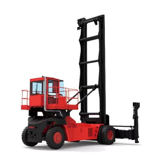
performance, structure, operation and maintenance etc of the CPCD180EC,
CPCD250EC series empty container handler in order that the operator can make
proper use and maintenance.
The operators concerned and equipment management personnel of the users in
the course of operation must fully read and understand this instruction manual,
perform operation and maintenance according to the relevant requirements and
stipulations in it so as to always keep the empty container handler in good operation
state.
Please note that our relevant commitments will be invalid if the requirements and
stipulations in the instruction manual have failed to be followed.
Since the products and components are under constant improvement, the relevant
contents of this manual are subject to any change without prior notice, please
understand.
FORWARD
Advertisement
Table of Contents

Subscribe to Our Youtube Channel
Related Manuals for HELI CPCD180EC Series


Summary of Contents for HELI CPCD180EC Series
- Page 1 FORWARD This instruction manual mainly contains the contents of the relevant safety, performance, structure, operation and maintenance etc of the CPCD180EC, CPCD250EC series empty container handler in order that the operator can make proper use and maintenance. The operators concerned and equipment management personnel of the users in the course of operation must fully read and understand this instruction manual,...
- Page 2 I. Safety and Operation Safety Rules of Empty Container Handler The driver and managing personnel of the empty container handler must keep firmly in mind “Safety First” and carry out safety and standardized operation according to the Operation & Service Manual and Operator’s Manual for the empty container handler.
- Page 3 battery. (3) Check hydraulic oil volume, braking hydraulic oil volume, accelerator oil-can level. (4) Check the air pressure of tire. (5) Check piping, joints, pumps and valves for leakage or damage. (6) Check forward and reverse gear handle to see if they are in the middle position or not (neutral position).
- Page 4 protective units of the vehicle and spreader are not in effect. (6) Perform loading and unloading strictly according to relevant requirements for the spreader and whole vehicle. (7) Lifting, lowering and running are forbidden when the lifted container deviates from the central line. Lateral movement function of spreader is allowed only at standstill of the vehicle.
- Page 5 when it lifts an object at high level. (13) Be careful when traveling on a slope. Move forward when climbing and backward when descending on a slope of above 1/10. Steering is not allowed when climbing and descending on a slope to prevent overturning. No handling operation when climbing on a slope.
- Page 6 (23) Strictly forbid adjusting the vehicle parts or performing overhaul and maintenance during loading and unloading. (24) Forbid sudden turn in direction at high speed when the empty container handler travels. (25) Fill the tyres according to the pressure value specified by the “Tyre Pressure” label..
-
Page 7: Table Of Contents
II. Main Components and Technical Parameters of the Empty Container Handler 1. The Empty Container Handler Mainly Consists of Such Parts as Listed Below: Name Contents Mainly includes engine, air filter, radiator, intake and Engine installation exhaust system, etc. Mainly includes torque converter, gearbox assembly, Main drive system drive shaft, drive axle, etc. - Page 8 2. Technical Parameter of Empty Container Handler...
- Page 9 Manufacturer HELI Model CPCD180EC CPCD250EC Rated capacity 8000 9000 Loading center 1220 1220 5(9’6″) 7(8′6″) Max. handling layers Length of container lifted 20 or 40 20 or 40 Max. rotary lock height 14960 18800 Min. rotary lock height 2300 2300...
- Page 10 III. Startup, Moving and Operation of the Empty Container Handler 1. Running-in Period We propose at least 200-hour running-in period for a new empty container handler. Pay attention to following matters in the running-in period: (1) Fully warm the engine each time after its startup and avoid high-speed running immediately after it is started up.
- Page 11 Engine startup steps are as follows: a) Sit on the driver’s seat; b) Switch on the main switch; c) Insert the ignition key into the ignition lock hole and turn it clockwise to gear 1 (switch-on gear) and the instrument system is wired up. d) Turn the ignition key clockwise to gear 2 (startup gear) to start up the engine.
- Page 12 b) Turn the ignition key to the position “off” and cut off the power making the engine stop running and then take out the key. 3. Initial- start Running and Stoppage of Empty Container Handler (1) Initial- start running of empty container handler: Procedures for startup and running of empty container handler are as follows: a) Press down parking brake button to free parking brake;...
- Page 13 the more the speed will be reduced. b) Choose a suitable gear position for acceleration and deceleration of empty container handler according to load and road surface conditions. CAUTION a) The action must be smooth for acceleration and deceleration of the engine.
- Page 14 d) Gear position state of gearbox is shown in the APC72 display of the right central console. e) The seesaw switch as shown in the diagram realizes manual/automatic state switching, during which all vehicle actions must be at pause and the gear changing handle in neutral position.
- Page 15 eliminate any trouble. (2) Pay attention to display of each instrument during traveling of empty container handler a) Oil meter of engine; b) Water temperature of engine: To reach the red area is not allowed; c) Engine tachometer: Rotation speed is not allowed to exceed the engine maximum;...
- Page 16 brake as emergency brake. (3) Service brake Used for speed control in frequent and usual running and parking When the pedal angle increases as the pedal is step down, the braking force will grow and braking effect will be more noticeable. WARNING Service braking action should be gentle.
- Page 17 pilot control handle respectively and the latter 2 by a seesaw switch on right console. a) Rotary lock opening: controlled by button 1 as shown in the figure. b) Rotary lock locking: controlled by button 2 as shown in the figure. c) Left move: controlled by button 3 as shown in the figure.
- Page 18 spreader width according to the width extension of container and laterally move the spreader to the central position, lift the mist so that the spreader can be raised to the appropriate height where the container can be lifted. c) Tilt mast forward, move spreader laterally for tuning and make sure that the rotary lock of spreader is located just above the corner lock hole of the container.
- Page 19 (2) Stacking containers Stack containers according to steps as follows: a) Fully tilt mast backward to make it approach container-stacking place or container lorry. b) When approaching container-stacking place or container lorry, lift mast up to an appropriate level for stacking container. c) Then move the vehicle forward slowly, nearing container-stacking place or container lorry.
- Page 20 back the vehicle in straight line at least for 3m. Carefully drive it to avoid fierce actions. i) Lower mast to descend spreader to normal running position of vehicle. WARNING Do not over tilt, suddenly shove or rapidly descend container, for the container to be stacked and the weight of spreader may do damage to the container below or the chassis of container lorry.
- Page 21 IV. About Main Parts of Empty Container Handler and Maintenance 1. Power system Power system includes engine installation, intake system, cooling system, exhaust system, etc of the engine. The engine is integrated with transmission unit and its bracket is connected with vehicle frame by buffering rubber spacer to reduce vibration.
-
Page 22: Main Drive System
c) In case of antifreeze used for coolant, forbid adding water and different types of antifreeze willfully. Supplement same type of antifreeze timely after it leaks or evaporates. d) In case of water used for coolant, it may freeze in cold weather as the vehicle is parked, so the water in radiator should be let out. - Page 23 oil level is over low, gearbox and clutch cannot be lubricated, as a result, the gearbox will be damaged and its performance undermined. If the oil level is over high, the oil foam will make gearbox over hot. Check the oil level of gearbox once every 200 hours according to methods listed below: a) Start empty container handler making the gearbox oil temperature rise to normal working temperature(80~110°);...
- Page 24 gearbox oil and filter element must be shortened. (2) Drive shaft Once every 100 hours: Use manual grease gun (never use high-pressure grease gun) to feed oil to universal joint through the fill plug. Overflow indicates fullness. Once every 400 hours: Check the tightness of torque of tightening bolt of transmission shaft.
- Page 25 valve, thus confining the movement and speed of the actuator. Through pressure-gradient control valve, hydraulic oil is first allocated to load sensing steering unit to control the action of steering oil cylinder and rest of the oil is fully supplied to main oil circuit.
- Page 26 Restore the screw plug; ● Fill fresh oil through oil inlet; ● Start up engine and make lifting operations to mast, diffusing hydraulic oil ● throughout the whole system; Lower mast, recheck oil level and fill it if needed. ● b) Oil cooler Oil cooler is located at the lower part of front machine cover.
- Page 28 4. Steering System (1) Brief description The steering system mainly consists of low-torque load sensing type all hydraulic steering gear and traversing unit assembly. The steering handwheel can be adjusted up and down, forward and back to suite the need of the operator. The low-torque load sensing type all hydraulic steering gear has excellent pressure compensation to the change of the steering load.
- Page 29 gear will connect with the pipe of oil pump, the connection marked “Return”(回) will connect with oil reservoir. The connections marked “Left”(左) and “Right”(右) will be connected with the left and right chambers of the cylinder respectively. The flow rate allowable in the suction pipe is 1—1.5m/s, pressure oil pipe and return oil pipe 4—5m/s.
- Page 30 If something abnormal happen during operation, try to find the reasons. Never turn the steering wheel by two people simultaneously. To keep the steering system in a good working condition and prevent accidents, water content, mechanical impurities and acid value of the working oil will be checked periodically.
- Page 31 5. Steering Axle (1) Brief description The steering axle is of welding structure type of trunk type cross section (refer to diagrams below). It consists of steering axle body, steering oil cylinder, connecting rod and steering wheel. The steering trapezium uses crank slide mechanism. The piston rod of the oil cylinder pushes steering knuckle to turn through the connecting rod.
- Page 32 (2) Steering knuckle and king pins of steering knuckle The steering knuckle is fixed between upper and lower shaft sleeves at the two ends of steering axle with king pins, thrust bearings and adjusting gaskets. The center of the swivel pin is fixed on the steering knuckle with clamp pins. The two ends of the swivel pin are supported by needle bearing.
-
Page 33: Braking System
6. Braking System (1) Braking oil tank It is situated at the right side of the forklift. Braking hydraulic oil in the tank acts on the driving axle. Everyday park the vehicle on horizontal ground and apply parking brake. Check oil level with relevant oil scale and fill oil through oil inlet when necessary. - Page 34 Check the cleanness of oil tank and clean it; ● Re-place the screw plug; ● Fill fresh oil through oil inlet; ● Start up engine, diffusing hydraulic oil throughout the whole system; ● Stop engine, check oil level and fill it if needed. ●...
-
Page 35: Lifting System
7. Lifting System 7.1 The composition of the lifting system Lifting system is of 2-order rolling-type vertical extension, consists of outer mast, inner mast, lifting oil cylinder, titling oil cylinder and lifting chain, etc. -
Page 36: Spreader
(1) Inner and outer masts Inner and outer masts are all welded parts. Outer mast bottom is fixed at driving axle with pin. The middle part of outer mast is connected with vehicle frame by tilted oil cylinder and can be dipped forward and backward under the action of tilted oil cylinder. - Page 37 (3) Carry out following work every 400 hours: Carefully check roller and chain wheel to see if they work normally, check the whole structure of mast, especially to see if all shaft pins are secure and the degree of tightness of pins. Make sure that the hoist oil cylinder and tilted oil cylinder work normally.
- Page 38 necessary to clean chain carefully with diluents before lubrication. d) Lubrication type For usual lubrication, the option can be lubricating oil with viscosity indication ISO VG46460. The oil with less viscosity can be applied to lower outdoor temperature and smaller chain. Compared with more viscous lubricating oil, the diluted oil enters into the chain joints easily and achieves better result of lubrication.
- Page 39 the first step is to place spreader at the lowest level, adjust the chain top joint and nuts, keeping two chains in equal tightness. g) Checking chain parts Take the chain apart regularly to clean it completely and check if there is any trouble with it and then lubricate the whole chain again if possible.
- Page 40 or rule having enough length. Pin shaft head or chain piece fringe values can be used for reference. Before measurement, put a light object (of about the forklift weight) on the straight and flat part of chain, fix the maximum extension limit at 2% although 3% is reachable in normal conditions.
-
Page 41: Electric System
l) Abrasion of chain Abrasion is resulted from poor engagement of chain interfaces with pulley or side pulley. Pulley side abrasion is generally caused by load deviated from central position or guide pulley/lift hook unit not in straight arrangement. Abraded pin shaft head is unable to firmly fix chain pieces and abrasion around chain pieces will affect disc similarly. - Page 42 is cooled .Check the electrolyte density when the battery cell is fully charged. Temperature Electrolyte Concentration(g/dm +40℃ 1265 +20℃ 1285 0℃ 1300 -20℃ 1365 8.2 Generator (Refer to the instruction of engine manufacture provided with the machine) Routine maintenance: Check if the wiring is good.
- Page 43 For every 1600 hours, carefully clean slip ring and check the wear and connection condition of the carbon brush. If necessary, change carbon brush handles with same type as the original. 8.3 Starting motor (Refer to the instruction of engine manufacture provided with the machine) Routine maintenance: Check if the connection wires are ok.
- Page 44 WARNING Do not install halogen lamp bulb directly by hand or the function of the bulb will be affected. (1) Front Lamp Cluster Main lamp: JOD H5 70W halogen lamp; Steering signal lamp: 21W; Width signal lamp: 5W. a) Bulb change ●...
- Page 45 (2) Rear Lamp Cluster Assembly It includes: Width lamp (5W globe lamp) Braking lamp (21 W globe lamp) Steering signal lamp (21 W globe lamp) backup light (10W) Bulb Change: ● Loosen the tightening screw of the lamp shade and take away the shade. ●...
- Page 46 (4) Yellow Warning Light Rotating lamp (35W bulb) Bulb Change: ● Take away the tightening screws (12) of the lamp shade. ● Change bulb and buzzer (sound level ≥90dB). (5) Spreader Lamps (6) Side Chamber Lamp Side chamber lamp (55W Ball-type bulb) Bulb Change: ●...
- Page 47 Table of Bulbs Name Type Watts Front lamp cluster/Main lamp Halogen bulb Front width lamp Ball-type bulb Front directional signal lamp Ball-type bulb Rear lamp cluster assembly Width lamp/Braking lamp/Steering signal lamp Ball-type bulb 5/21/21 Backup lamp Ball-type bulb Working lamp Halogen bulb Yellow warning lamp Ball-type bulb...
- Page 48 Current (A) Protection Power source for hydraulic pressure auxiliary control unit Power source for transmission control Braking lamp Power source for braking system signal control Electrical fan for braking hydraulic pressure Air conditioner Driver’s cab 8.5 Electronic control elements (1) Preventive measures of the electronic control element Prevent that the forklift is improperly operated.
- Page 49 control cabinet mounted on the spreader. (2) Safety prompts for use of spreader a) The operators must be trained and read carefully the instruction and make sure that they are familiar with its operation method. b) The safety of you and the people nearby all depend on your correct operation of the spreader.
- Page 50 n) When the spreader locks the container, the spreader is not allowed to be laterally moved. o) The vehicle should be checked and see if all the safety devices work normally when it is not used for along time. p) If the spin lock or lifting hook can not lock the container, check if the container is deformed.
- Page 51 Circuit diagram refer to attached circuit diagram of the forklift. Maintenance Table Maintenance steps: C=Check c=Clean A=Adjustment R=Change Interval Name Lamps Every day Control & indicator lamps Every week Spreader Lock knob or lifting hook Oil cylinder base Every Pulley and bearing hours Block and idler pulley Electronic inductor...
- Page 52 8.6 Air conditioning Air conditioning can be used only after the engine is working. The air enters into the drive cab through the adjustable vent hole which is on the ventilation pipe and independent of the ventilation control of preheater. The air conditioning control panel on the operation console at the right side of the cab can be used to turn on the air conditioner and set the temperature needed..
- Page 53 Make sure all vent holes and windows are closed. If the vehicle is used after parking in the sunshine for a long time, turn the wind speed control knob to position III and open windows to speed up the refrigeration of the cab. Do not let the wind blow on the people directly.
- Page 54 After starting, test braking and parking braking immediately. If there are problems with one or two braking system, please contact after-sales service department immediately. 8.8 Engine (please refer to the attached instruction of the engine manufacturer) WARNING If the engine will be started in a closed area, please check first if there is good ventilation as discharged gas is poisonous.
- Page 55 CAUTION If the engine can not start, the time to crank the engine should not exceed 30 seconds or it will damage the engine and cause leakage in battery cell. After engine starts, move the vehicle slowly to make the engine run at low speed and reach operation temperature gradually.
- Page 56 Before traveling operation, check the battery cell warning light, low engine oil pressure and low braking oil warning lights. If one of the warning lights is on, it means there is trouble. Please contact the service department of Heli. Start the vehicle according to following procedures: a) Connect parking brake button (on the right front of the control box) and step down the braking pedal.
- Page 57 Ⅴ.Others The oil consumption of empty container handler Name Brand No.(Code) Recommended Fuel(Diesel oil) In summer 0#,in winter-10# Gear lubricating oil of Titan Gear LS90(85W-90) FUCHS drive axle Driving oil of gearbox SG/CF-4 15W-40 FUCHS Lubricating oil of engine SG/CF-4 15W-40 FUCHS Hydraulic oil for braking...
Need help?
Do you have a question about the CPCD180EC Series and is the answer not in the manual?
Questions and answers