Table of Contents
Advertisement
Quick Links
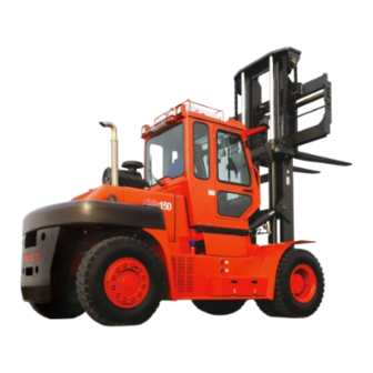
This manual accounts for "HELI" Forklift Truck of CPCD140~160 type,
includes its performance, constructure, safe operation and regular preventive
maintenance, so that operators, mechanics and supervisors of Forklift Truck correctly
operate and prevent maintenance.
Read and understand this manual before operating your lift truck! This manual is
your guide to safe operation and regular preventive maintenance. So as to let the
Forklift Truck keep good working conditions.
If any operation or maintenance doesn't accord with requires in this manual, our
related promises is inefficacy.
Due to continuous improvements in design, it is possible that the latest
description contained herein may differ slightly from the truck delivered to you.
Moreover, the specification of the forklift truck may be changed insignificantly
depending on its destination.
FOREWORD
Advertisement
Table of Contents


Need help?
Do you have a question about the CPCD140 and is the answer not in the manual?
Questions and answers